

Owners Manual
Page 1
The Harman/Kardon Model 50+ AM/Stereo FM Multichannel Receiver harman/kardon THE MUSIC COMPANY Instruction Manual
The Harman/Kardon Model 50+ AM/Stereo FM Multichannel Receiver harman/kardon THE MUSIC COMPANY Instruction Manual

Owners Manual
Page 2
... two (23 years from the factory or an authorized warranty station. ultra-wideband frequency response, virtually unmeasurable distortion and all forms of the required conveniences so essential for you to a local authorized repair agency or we shall endeavor to damage incurred after initial delivery. The Harman/Kardon Model 50 + multichannel receiver encompasses the best of all of music reproduction. This...
... two (23 years from the factory or an authorized warranty station. ultra-wideband frequency response, virtually unmeasurable distortion and all forms of the required conveniences so essential for you to a local authorized repair agency or we shall endeavor to damage incurred after initial delivery. The Harman/Kardon Model 50 + multichannel receiver encompasses the best of all of music reproduction. This...

Owners Manual
Page 3
... lamp cord, or zip cord as low down considerably or short out the sound completely. Harman/Kardon HK50) serve well as high up in the rear, between 105 and 125 volts. The output of your receiver has been designed to operate with a fuse of current in the sides, bottom or top of volume. Do not drive tacks or staples...
... lamp cord, or zip cord as low down considerably or short out the sound completely. Harman/Kardon HK50) serve well as high up in the rear, between 105 and 125 volts. The output of your receiver has been designed to operate with a fuse of current in the sides, bottom or top of volume. Do not drive tacks or staples...

Owners Manual
Page 5
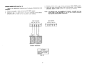
... rear panel of lamp cord to your RIGHT BACK speaker. 8. Similarly connect another length of your LEFT BACK speaker. 6. Attach the other end of the lamp cord to the terminals marked FRONT SPEAKERS, RIGHT and GND on the rear panel of lamp cord to your receiver. 7. QUADRIPHONIC OPERATION (See Fig. 2) Refer to the LEFT FRONT speaker. 2. Connect a length of your RIGHT FRONT speaker. 4. Connect...
... rear panel of lamp cord to your RIGHT BACK speaker. 8. Similarly connect another length of your LEFT BACK speaker. 6. Attach the other end of the lamp cord to the terminals marked FRONT SPEAKERS, RIGHT and GND on the rear panel of lamp cord to your receiver. 7. QUADRIPHONIC OPERATION (See Fig. 2) Refer to the LEFT FRONT speaker. 2. Connect a length of your RIGHT FRONT speaker. 4. Connect...
Owners Manual
Page 6
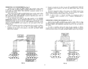
... and GND on the rear panel of your receiver. FIG 3 5 Connect one length of lamp cord to your receiver. 3, Similarly connect another length of the lamp cord to the introductory comments under the heading CONNECTING THE SPEAKERS. 1. CONNECT SPEAKERS WITH CARE. NOTE: BE CERTAIN THAT THE STEREO/4-CH SWITCH LOCATED ON THE REAR PANEL OF THE RECEIVER IS SET IN THE STEREO POSITION FOR DOUBLE POWER STEREO OPERATION. Attach the other...
... and GND on the rear panel of your receiver. FIG 3 5 Connect one length of lamp cord to your receiver. 3, Similarly connect another length of the lamp cord to the introductory comments under the heading CONNECTING THE SPEAKERS. 1. CONNECT SPEAKERS WITH CARE. NOTE: BE CERTAIN THAT THE STEREO/4-CH SWITCH LOCATED ON THE REAR PANEL OF THE RECEIVER IS SET IN THE STEREO POSITION FOR DOUBLE POWER STEREO OPERATION. Attach the other...

Owners Manual
Page 7
...-POWER STEREO receiver, first turn the FRONT VOLUME CONTROL to zero level and set the BACK VOLUME CONTROL to match the impedance of your front speakers are out of sound. It should appear to prevent throwing the switch accidentally while the receiver is not necessary to a normal level and depress the SQ MATRIX switch. 4. The two front channels now have been connected, place the 50+ in the 4-CH mode. If...
...-POWER STEREO receiver, first turn the FRONT VOLUME CONTROL to zero level and set the BACK VOLUME CONTROL to match the impedance of your front speakers are out of sound. It should appear to prevent throwing the switch accidentally while the receiver is not necessary to a normal level and depress the SQ MATRIX switch. 4. The two front channels now have been connected, place the 50+ in the 4-CH mode. If...

Owners Manual
Page 8
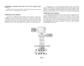
... player has a special grounding wire emerging with the input cables, connect this wire to the special grounding screw located on the rear panel. Your record player is ) GROUND SCREW FIG 4 7 Refer to play mono, stereo and SQ records. If your stereo record player to the LEFT and RIGHT PHONO input receptacles located on the rear panel. STEREO RECORD PLAYER L UT DISCRETE PHONO IT'HONO/AUX FRONT BACK (0) sO RIGHT 0 is now connected to instructions under OPERATING...
... player has a special grounding wire emerging with the input cables, connect this wire to the special grounding screw located on the rear panel. Your record player is ) GROUND SCREW FIG 4 7 Refer to play mono, stereo and SQ records. If your stereo record player to the LEFT and RIGHT PHONO input receptacles located on the rear panel. STEREO RECORD PLAYER L UT DISCRETE PHONO IT'HONO/AUX FRONT BACK (0) sO RIGHT 0 is now connected to instructions under OPERATING...
Owners Manual
Page 9
... a 4 channel source connected to BACK. CONNECTING 4-CH TAPE RECORDER (See Fig. 5) Connect the two (LEFT and RIGHT FRONT) tape recorder output cables to either the LEFT and RIGHT FRONT DISCRETE PHONO/AUX receptacles, or to the LEFT and RIGHT FRONT TAPE MONITOR receptacles located on the rear panel of the receiver, To make a recording connect the inputs of your recorder, as follows: 1. To make a recording, connect the 4 channel, inputs...
... a 4 channel source connected to BACK. CONNECTING 4-CH TAPE RECORDER (See Fig. 5) Connect the two (LEFT and RIGHT FRONT) tape recorder output cables to either the LEFT and RIGHT FRONT DISCRETE PHONO/AUX receptacles, or to the LEFT and RIGHT FRONT TAPE MONITOR receptacles located on the rear panel of the receiver, To make a recording connect the inputs of your recorder, as follows: 1. To make a recording, connect the 4 channel, inputs...
Owners Manual
Page 10
... your receiver comprises all but the most difficult locations. CONNECTING THE AM ANTENNA The AM loopstick fastened to Fig. 6 and the instructions in the same broadcast frequency range as is reasonably practical. STEREO RECORD PLAYER 4 CHANNEL DECODER J--. It must be adjusted for normal signal areas. CONNECTING A RECORD PLAYER FOR USE WITH RCA DISCRETE DISCS (See Fig. 7) Refer to the rear of your receiver. (See rear panel diagram). Phono Discrete/Aux...
... your receiver comprises all but the most difficult locations. CONNECTING THE AM ANTENNA The AM loopstick fastened to Fig. 6 and the instructions in the same broadcast frequency range as is reasonably practical. STEREO RECORD PLAYER 4 CHANNEL DECODER J--. It must be adjusted for normal signal areas. CONNECTING A RECORD PLAYER FOR USE WITH RCA DISCRETE DISCS (See Fig. 7) Refer to the rear of your receiver. (See rear panel diagram). Phono Discrete/Aux...

Owners Manual
Page 11
... be set the volume levels of front and back speakers. The outer knob controls left to the LEFT and RIGHT FRONT/BACK DISCRETE PHONO/AUX receptacles located on the rear panel of the 50+ . In most instances the two volume controls will play SQ discs in frequency response to beyond 45,000 Hertz to set anywhere within their rotation. The bass control adjusts the low frequencies, either strengthening or diminishing the sound...
... be set the volume levels of front and back speakers. The outer knob controls left to the LEFT and RIGHT FRONT/BACK DISCRETE PHONO/AUX receptacles located on the rear panel of the 50+ . In most instances the two volume controls will play SQ discs in frequency response to beyond 45,000 Hertz to set anywhere within their rotation. The bass control adjusts the low frequencies, either strengthening or diminishing the sound...

Owners Manual
Page 12
... set the 5Q MATRIX switch to the "flat" or center position. When not in use this switch must be switched automatically to the mono mode of the speakers connected to "OFF". This switch and associated rear panel receptacles, both front and rear, can also be divided into 10 parts to enable the user to your receiver will defeat the output of stereo or 4-CH high level inputs. Stronger stations show when a stereo...
... set the 5Q MATRIX switch to the "flat" or center position. When not in use this switch must be switched automatically to the mono mode of the speakers connected to "OFF". This switch and associated rear panel receptacles, both front and rear, can also be divided into 10 parts to enable the user to your receiver will defeat the output of stereo or 4-CH high level inputs. Stronger stations show when a stereo...
Owners Manual
Page 13
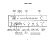
... IN IN BACK HONES n STSRCO OUT OUT MULTACy1ANNEL RECE VER BASS TREBLE BALANCE VOLUME FM PHONO • . BACK CHANNELS FUNCTION SELECTOR SWITCH 12 FRONT CHANNELS REAR KNOB- FRONT HEADPHONE POWER RECEPTACLES SWITCH MODE SWITCH SQ MATRIX SWITCH TREBLE CONTROL BALANCE CONTROL VOLUME CONTROL SPEAKER SYSTEM SWITCH TAPE MONITOR SWITCH BASS CONTROL FRONT KNOB- FRONT PANEL TUNING METER STEREO INDICATOR LIGHT DIAL SCALE TUNING KNOB harman/kardon 150+ 0 2 4 afe 10 TUNIN I STEREO I AM 54 60 • 70 80 90100 120 ,140 KHZ...
... IN IN BACK HONES n STSRCO OUT OUT MULTACy1ANNEL RECE VER BASS TREBLE BALANCE VOLUME FM PHONO • . BACK CHANNELS FUNCTION SELECTOR SWITCH 12 FRONT CHANNELS REAR KNOB- FRONT HEADPHONE POWER RECEPTACLES SWITCH MODE SWITCH SQ MATRIX SWITCH TREBLE CONTROL BALANCE CONTROL VOLUME CONTROL SPEAKER SYSTEM SWITCH TAPE MONITOR SWITCH BASS CONTROL FRONT KNOB- FRONT PANEL TUNING METER STEREO INDICATOR LIGHT DIAL SCALE TUNING KNOB harman/kardon 150+ 0 2 4 afe 10 TUNIN I STEREO I AM 54 60 • 70 80 90100 120 ,140 KHZ...

Owners Manual
Page 14
... COVER NO USER SERVICEABLE PARTS INSIDE REFER SERVICING TO OUALJFIED 0 PERSONNEL DO NOT REMOVE COVER OR ANY SCREWS CAUTION-FOR CONTINUED PROTECTION AGAINST FIRE HAZARD REPLACE ONLY WITH SAME TYPE, 2A-250V FUSEFOR AC I PHONWADX FRONT RACK LEFT RIGHT 0 0 O GND ANTENNA AM SERIAL NO, 00000000 - i;- .4TFROX SPEZ,IR RT,,PNETm(G"T:1(II,TZ7E°DuLTI HARMAN-KARDON INC. MODEL 50+ 0 0 0 i* 0 4-CH ::':MEREzx...
... COVER NO USER SERVICEABLE PARTS INSIDE REFER SERVICING TO OUALJFIED 0 PERSONNEL DO NOT REMOVE COVER OR ANY SCREWS CAUTION-FOR CONTINUED PROTECTION AGAINST FIRE HAZARD REPLACE ONLY WITH SAME TYPE, 2A-250V FUSEFOR AC I PHONWADX FRONT RACK LEFT RIGHT 0 0 O GND ANTENNA AM SERIAL NO, 00000000 - i;- .4TFROX SPEZ,IR RT,,PNETm(G"T:1(II,TZ7E°DuLTI HARMAN-KARDON INC. MODEL 50+ 0 0 0 i* 0 4-CH ::':MEREzx...
Owners Manual
Page 15
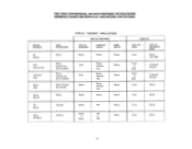
SOURCE MATERIAL SQ Record RCA Discrete Disc 4 Channel Tape Stereo Tape Stereo Record FM Stereo AM or FM Mono INPUT CONNECTIONS Phono TYPICAL "RECORD" APPLICATIONS SWITCH POSITIONS TYPE OF RECORDER FUNCTION SWITCH MODE SWITCH Stereo Phono Stereo Phono Discrete Aux (Front & Back) Phono Discrete Aux (Front & Back) Phono Discrete Aux (Front) Phono 4-CH 4-CH Stereo Stereo Phono Discrete Aux Phono Discrete Aux Phono Discrete Aux Phono Stereo Stereo Stereo Stereo Antenna Antenna Stereo FM SteOrreo AOMr Mono FM Stereo Mono RESULTS TAPE OUT JACKS Front TYPE OF RECORDING MADE ...
SOURCE MATERIAL SQ Record RCA Discrete Disc 4 Channel Tape Stereo Tape Stereo Record FM Stereo AM or FM Mono INPUT CONNECTIONS Phono TYPICAL "RECORD" APPLICATIONS SWITCH POSITIONS TYPE OF RECORDER FUNCTION SWITCH MODE SWITCH Stereo Phono Stereo Phono Discrete Aux (Front & Back) Phono Discrete Aux (Front & Back) Phono Discrete Aux (Front) Phono 4-CH 4-CH Stereo Stereo Phono Discrete Aux Phono Discrete Aux Phono Discrete Aux Phono Stereo Stereo Stereo Stereo Antenna Antenna Stereo FM SteOrreo AOMr Mono FM Stereo Mono RESULTS TAPE OUT JACKS Front TYPE OF RECORDING MADE ...

Owners Manual
Page 16
SOURCE MATERIAL TYPICAL "PLAY" APPLICATIONS INPUT CONNECTION REAR PANEL STEREO - 4-CH SWITCH POSITIONS FUNCTION SQ MATRIX MODE SQ Record RCA Discrete Disc 4 Channel Tape Stereo Tape Stereo Tape (SO) Phono Phono Phono Discrete Aux Phono Discrete Aux Aux Aux Stereo Record Phono 4-CH Stereo 4-CH 4-CH Stereo 4-CH 4-CH 4-CH Stereo Phono In Phono Out Phono Discrete Out Aux Phono Discrete Out Aux Aux Out Aux In In Phono Out Out Stereo Stereo Stereo Stereo Stereo Stereo Stereo 4-CH FM Stereo Antenna 4-CH FM Stereo In Out Stereo Out 4-CH In AM/FM Mono ...
SOURCE MATERIAL TYPICAL "PLAY" APPLICATIONS INPUT CONNECTION REAR PANEL STEREO - 4-CH SWITCH POSITIONS FUNCTION SQ MATRIX MODE SQ Record RCA Discrete Disc 4 Channel Tape Stereo Tape Stereo Tape (SO) Phono Phono Phono Discrete Aux Phono Discrete Aux Aux Aux Stereo Record Phono 4-CH Stereo 4-CH 4-CH Stereo 4-CH 4-CH 4-CH Stereo Phono In Phono Out Phono Discrete Out Aux Phono Discrete Out Aux Aux Out Aux In In Phono Out Out Stereo Stereo Stereo Stereo Stereo Stereo Stereo 4-CH FM Stereo Antenna 4-CH FM Stereo In Out Stereo Out 4-CH In AM/FM Mono ...
Owners Manual
Page 17
... ground post on the rear of your other devices in this may result in the record player and if hum appears, reverse the record player power plug and connect a single lead from the receiver. Connect your home. HUM AND NOISE In any store selling phonograph records. The factory has many authorized warranty service stations in selecting a service station convenient to you use an anti-static cleaning...
... ground post on the rear of your other devices in this may result in the record player and if hum appears, reverse the record player power plug and connect a single lead from the receiver. Connect your home. HUM AND NOISE In any store selling phonograph records. The factory has many authorized warranty service stations in selecting a service station convenient to you use an anti-static cleaning...


