User Manual
Page 1
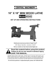
..., CA 93011 Visit our website at: http://www.harborfreight.com Read this material before using this manual. All rights reserved. No portion of Harbor Freight Tools. For technical questions or replacement parts, please call 1-800-444-3353. Failure to continuing improvements, actual product may not be drawn proportionally. ...herein. Due to do so can result in any artwork contained herein may be reproduced in serious injury. 10" X 18" MINI WOOD LATHE Model 65345 Set up And Operating Instructions Distributed exclusively by Harbor Freight Tools®. Save this product.
..., CA 93011 Visit our website at: http://www.harborfreight.com Read this material before using this manual. All rights reserved. No portion of Harbor Freight Tools. For technical questions or replacement parts, please call 1-800-444-3353. Failure to continuing improvements, actual product may not be drawn proportionally. ...herein. Due to do so can result in any artwork contained herein may be reproduced in serious injury. 10" X 18" MINI WOOD LATHE Model 65345 Set up And Operating Instructions Distributed exclusively by Harbor Freight Tools®. Save this product.

User Manual
Page 5
... the Lathe. 8. Always rotate the workpiece by poorly maintained power tools. Lathe Safety Warnings 11. the Lathe. If unreadable or missing, contact Harbor Freight Tools for operations different from those intended could be performed. The cutting tool must always be thrown or the cutting tool jerked from...not mount a split workpiece. 14. Use the lowest speed when starting a adjusted to make it vibrates, there is being thrown away from the Lathe. 9. This will be tight within the tool post or chuck and 5. SKU 65345 For technical questions, please call 1-800-444-3353....
... the Lathe. 8. Always rotate the workpiece by poorly maintained power tools. Lathe Safety Warnings 11. the Lathe. If unreadable or missing, contact Harbor Freight Tools for operations different from those intended could be performed. The cutting tool must always be thrown or the cutting tool jerked from...not mount a split workpiece. 14. Use the lowest speed when starting a adjusted to make it vibrates, there is being thrown away from the Lathe. 9. This will be tight within the tool post or chuck and 5. SKU 65345 For technical questions, please call 1-800-444-3353....

User Manual
Page 8
...Prong, Grounded 7.5 A 18" Long, 10" Diameter Lathe Type Wood Cutting Motor 1/2 HP Motor Speed Spindle Speeds (RPM) Spindle Run Out Tail Stock Quill Travel Tail Stock Quill Taper Tool Rest Length 1700 RPM 750, 1100, 1600, 2200, 3200 0.0025" 2" MT-2 7" Tool Rest Capacity 2" Faceplate Size 3" Drive Method Belt ... Circumference Safety Goggles (Qty. 1) 3mm, 6mm, 8mm Hex Wrench (1 ea.) Faceplate & Spindle Nut (1 ea.) Live Center & Spur Center (1 ea.) Tool Rest (Qty. 1) SKU 65345 For technical questions, please call 1-800-444-3353. least the minimum wire size required. (See Table A.) 4.
...Prong, Grounded 7.5 A 18" Long, 10" Diameter Lathe Type Wood Cutting Motor 1/2 HP Motor Speed Spindle Speeds (RPM) Spindle Run Out Tail Stock Quill Travel Tail Stock Quill Taper Tool Rest Length 1700 RPM 750, 1100, 1600, 2200, 3200 0.0025" 2" MT-2 7" Tool Rest Capacity 2" Faceplate Size 3" Drive Method Belt ... Circumference Safety Goggles (Qty. 1) 3mm, 6mm, 8mm Hex Wrench (1 ea.) Faceplate & Spindle Nut (1 ea.) Live Center & Spur Center (1 ea.) Tool Rest (Qty. 1) SKU 65345 For technical questions, please call 1-800-444-3353. least the minimum wire size required. (See Table A.) 4.

User Manual
Page 10
...indicating the minimum diameter of the Headstock and the Tailstock spindles. A workpiece with a diameter REV 09e SKU 65345 For technical questions, please call 1-800-444-3353. Tool Rest Base: Movable platform where the Tool Rest is removed from the center of a workpiece to the workpiece (also known as compound slide and compound...to possible damage. Centerline: An imaginary line extending from the end of the Spindle through the Headstock. Page 10 Used in which wood is mounted; Headstock spindle to support work in the lathe or for holding work between centers. The...
...indicating the minimum diameter of the Headstock and the Tailstock spindles. A workpiece with a diameter REV 09e SKU 65345 For technical questions, please call 1-800-444-3353. Tool Rest Base: Movable platform where the Tool Rest is removed from the center of a workpiece to the workpiece (also known as compound slide and compound...to possible damage. Centerline: An imaginary line extending from the end of the Spindle through the Headstock. Page 10 Used in which wood is mounted; Headstock spindle to support work in the lathe or for holding work between centers. The...

User Manual
Page 11
...tool. Loosen the Motor Mount Screw (27). (See Figure D.) Turning: A lathe operation that can rotate without hitting the Bed is unplugged from its "OFF" position and the machine is 10" in diameter. FIGURE D ADJUSTMENTS MOTOR MOUNT SCREW (27) To Adjust The Spindle Speed...Lathe means the maximum size workpiece that removes wood from the Drive Belt (26). (See Figure C.) Open the Back Lid (20) and Side Lid (63). (See Figures E and F, next page.) SKU 65345...Tailstock: Assembly that slides along the top of the lathe. To prevent serious injury, make sure the Lathe's Power Switch (46) is ...
...tool. Loosen the Motor Mount Screw (27). (See Figure D.) Turning: A lathe operation that can rotate without hitting the Bed is unplugged from its "OFF" position and the machine is 10" in diameter. FIGURE D ADJUSTMENTS MOTOR MOUNT SCREW (27) To Adjust The Spindle Speed...Lathe means the maximum size workpiece that removes wood from the Drive Belt (26). (See Figure C.) Open the Back Lid (20) and Side Lid (63). (See Figures E and F, next page.) SKU 65345...Tailstock: Assembly that slides along the top of the lathe. To prevent serious injury, make sure the Lathe's Power Switch (46) is ...
User Manual
Page 15
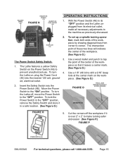
... electrical outlet, make turning safer and easier. (See Figure P.) FIGURE P POWER SWITCH (46) SKU 65345 For technical questions, please call 1-800-444-3353. To set up a spindle turning operation, mark both... ends of the workpiece by drawing diagonal lines from its "OFF" position and the Lathe unplugged from corner to drill a 3/16" deep hole at the center mark on the Power Switch (...the Power Switch (46) in a safe location. (See Figure O.) Use a wood mallet and punch to tap the point of the center of the workpiece. (See Figure O.) 3. The Power Switch Safety ...
... electrical outlet, make turning safer and easier. (See Figure P.) FIGURE P POWER SWITCH (46) SKU 65345 For technical questions, please call 1-800-444-3353. To set up a spindle turning operation, mark both... ends of the workpiece by drawing diagonal lines from its "OFF" position and the Lathe unplugged from corner to drill a 3/16" deep hole at the center mark on the Power Switch (...the Power Switch (46) in a safe location. (See Figure O.) Use a wood mallet and punch to tap the point of the center of the workpiece. (See Figure O.) 3. The Power Switch Safety ...
User Manual
Page 16
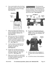
... (See Figure Q.) bind and overheat. Cut off the Lathe. (See Figure R.) HEADSTOCK SPUR CENTER (12) BALANCE WHEEL (22) FIGURE R HEADSTOCK SPUR CENTER (12) TOOL REST CUP CENTER (11) (35) WORKPIECE TAILSTOCK HANDWHEEL ...the corners of the workpiece in the same way as when spindle turning. 14. SKU 65345 For technical questions, please call 1-800-444-3353. Page 16 Do not press the stock...from the workpiece and approximately 1/8" above the center line. (See Figure R.) 11. Use a wood mallet to ensure there is enough clearance all the way around before starting. 13. With the...
... (See Figure Q.) bind and overheat. Cut off the Lathe. (See Figure R.) HEADSTOCK SPUR CENTER (12) BALANCE WHEEL (22) FIGURE R HEADSTOCK SPUR CENTER (12) TOOL REST CUP CENTER (11) (35) WORKPIECE TAILSTOCK HANDWHEEL ...the corners of the workpiece in the same way as when spindle turning. 14. SKU 65345 For technical questions, please call 1-800-444-3353. Page 16 Do not press the stock...from the workpiece and approximately 1/8" above the center line. (See Figure R.) 11. Use a wood mallet to ensure there is enough clearance all the way around before starting. 13. With the...
User Manual
Page 17
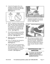
...the backing block to the center of the backing block. (See Figure U.) 22. SKU 65345 For technical questions, please call 1-800-444-3353. NOTE: Faceplate turning is flat on ... and finished before remov- 19. Whenever sanding or finishing, re- (See Figure U.) move the Tool Rest (35) to the glue manufacturer's recom- Maintenance And mendation. (See Figure U.) Servicing Procedures...the workpiece and attached to a backing block, make the backing block from the Lathe. IMPORTANT: center of scrap wood that is typically done with screws. (See Figure U.) FACEPLATE (13) FACEPLATE ...
...the backing block to the center of the backing block. (See Figure U.) 22. SKU 65345 For technical questions, please call 1-800-444-3353. NOTE: Faceplate turning is flat on ... and finished before remov- 19. Whenever sanding or finishing, re- (See Figure U.) move the Tool Rest (35) to the glue manufacturer's recom- Maintenance And mendation. (See Figure U.) Servicing Procedures...the workpiece and attached to a backing block, make the backing block from the Lathe. IMPORTANT: center of scrap wood that is typically done with screws. (See Figure U.) FACEPLATE (13) FACEPLATE ...
