
User Manual
Page 1
... technical questions or replacement parts, please call 1-800-444-3353. 10" X 18" MINI WOOD LATHE Model 65345 Set up And Operating Instructions Distributed exclusively by Harbor Freight Tools®. Save this manual or any shape or form without the express written consent of Harbor Freight Tools. Failure to continuing improvements, actual product may differ slightly from the product described herein. Copyright© 2008 by Harbor Freight Tools®. 3491...
... technical questions or replacement parts, please call 1-800-444-3353. 10" X 18" MINI WOOD LATHE Model 65345 Set up And Operating Instructions Distributed exclusively by Harbor Freight Tools®. Save this manual or any shape or form without the express written consent of Harbor Freight Tools. Failure to continuing improvements, actual product may differ slightly from the product described herein. Copyright© 2008 by Harbor Freight Tools®. 3491...

User Manual
Page 2
CONTENTS IMPORTANT SAFETY INFORMATION 3 GROUNDING 7 EXTENSION CORDS 7 SYMBOLOGY 8 SPECIFICATIONS 8 UNPACKING 9 PRODUCT FEATURES 9 ASSEMBLY INSTRUCTIONS 9 WORK AREA SET UP 9 DEFINITION OF TERMS 10 ADJUSTMENTS 11 OPERATING INSTRUCTIONS 15 MAINTENANCE AND SERVICING 17 PLEASE READ THE FOLLOWING CAREFULLY 18 TROUBLESHOOTING 19 PARTS LIST 20 ASSEMBLY DIAGRAM 21 WARRANTY INFORMATION 22 SKU 65345 For technical questions, please call 1-800-444-3353. Page 2
CONTENTS IMPORTANT SAFETY INFORMATION 3 GROUNDING 7 EXTENSION CORDS 7 SYMBOLOGY 8 SPECIFICATIONS 8 UNPACKING 9 PRODUCT FEATURES 9 ASSEMBLY INSTRUCTIONS 9 WORK AREA SET UP 9 DEFINITION OF TERMS 10 ADJUSTMENTS 11 OPERATING INSTRUCTIONS 15 MAINTENANCE AND SERVICING 17 PLEASE READ THE FOLLOWING CAREFULLY 18 TROUBLESHOOTING 19 PARTS LIST 20 ASSEMBLY DIAGRAM 21 WARRANTY INFORMATION 22 SKU 65345 For technical questions, please call 1-800-444-3353. Page 2

User Manual
Page 3
... safety a.Keep work area clean and well lit. Important SAFETY Information In this manual and the receipt in death or serious injury. NOTICE is used to address practices not related to avoid possible injury or death. General Power Tool Safety Warnings WARNING Read all safety messages that follow the warnings and instructions may ignite the dust or fumes. Write the product's serial number...
... safety a.Keep work area clean and well lit. Important SAFETY Information In this manual and the receipt in death or serious injury. NOTICE is used to address practices not related to avoid possible injury or death. General Power Tool Safety Warnings WARNING Read all safety messages that follow the warnings and instructions may ignite the dust or fumes. Write the product's serial number...

User Manual
Page 4
... parts. 4. Remove any adjustments, changing accessories, or storing power tools. Power tool use the power tool if the switch does not turn it was designed. c. Check for your body is an increased risk of the power tool may result in serious personal injury. Page 4 Do not expose power tools to unplug the power tool. Keep cord away from the power source before making any adjusting key or wrench before turning the power tool on and off. b.Use safety equipment. A wrench or a key...
... parts. 4. Remove any adjustments, changing accessories, or storing power tools. Power tool use the power tool if the switch does not turn it was designed. c. Check for your body is an increased risk of the power tool may result in serious personal injury. Page 4 Do not expose power tools to unplug the power tool. Keep cord away from the power source before making any adjusting key or wrench before turning the power tool on and off. b.Use safety equipment. A wrench or a key...

User Manual
Page 5
... could result in the workpiece before operating. Lathe Safety Warnings 11. Remove all locks before mounting between the 1. Maintain labels and nameplates on centers or on the Lathe. Use a brush or compressed air to the faceplate. never your power tool serviced by a qualified repair person using only identical replacement parts. The cutting tool must always be split or thrown from the Lathe. 9. Use the lowest speed when starting a adjusted to be 3. post. This will...
... could result in the workpiece before operating. Lathe Safety Warnings 11. Remove all locks before mounting between the 1. Maintain labels and nameplates on centers or on the Lathe. Use a brush or compressed air to the faceplate. never your power tool serviced by a qualified repair person using only identical replacement parts. The cutting tool must always be split or thrown from the Lathe. 9. Use the lowest speed when starting a adjusted to be 3. post. This will...

User Manual
Page 6
...- Industrial applications must be supplied by power sanding, sawing, grinding, drilling, and SKU 65345 For technical questions, please call 1-800-444-3353. Turn off -bal- or other masonry products • Arsenic and chromium from its electrical outlet before leaving. 24. this instruction 21. This product is plugged into a cutting tool against the direction of children. it Code § 25249.5, et seq.) from...
...- Industrial applications must be supplied by power sanding, sawing, grinding, drilling, and SKU 65345 For technical questions, please call 1-800-444-3353. Turn off -bal- or other masonry products • Arsenic and chromium from its electrical outlet before leaving. 24. this instruction 21. This product is plugged into a cutting tool against the direction of children. it Code § 25249.5, et seq.) from...

User Manual
Page 7
... a service facility before use a heavier gauge extension cord. The plug and outlet should electrically malfunction or break down, grounding provides a low 3. For example, a 14 gauge cord can use the tool if the power cord or plug is properly grounded. from incorrect grounding wire connection: Check with a qualified electrician if you must use . As the distance from the user, reducing the risk of the cord. Never remove...
... a service facility before use a heavier gauge extension cord. The plug and outlet should electrically malfunction or break down, grounding provides a low 3. For example, a 14 gauge cord can use the tool if the power cord or plug is properly grounded. from incorrect grounding wire connection: Check with a qualified electrician if you must use . As the distance from the user, reducing the risk of the cord. Never remove...

User Manual
Page 8
... it repaired by a qualified electrician before using an extension cord outdoors, make sure it is properly wired and in Canada) to five volts at 150% of the rated amperes. No Load (RPM) Revolutions per Minute Specifications Electrical Requirements Maximum Stock Length/Diameter 110 V~ / 60 Hz Power Cord: 18 AWG X 3C Power Plug: 3-Prong, Grounded 7.5 A 18" Long, 10" Diameter Lathe Type Wood Cutting Motor 1/2 HP Motor Speed Spindle Speeds (RPM) Spindle Run...
... it repaired by a qualified electrician before using an extension cord outdoors, make sure it is properly wired and in Canada) to five volts at 150% of the rated amperes. No Load (RPM) Revolutions per Minute Specifications Electrical Requirements Maximum Stock Length/Diameter 110 V~ / 60 Hz Power Cord: 18 AWG X 3C Power Plug: 3-Prong, Grounded 7.5 A 18" Long, 10" Diameter Lathe Type Wood Cutting Motor 1/2 HP Motor Speed Spindle Speeds (RPM) Spindle Run...
User Manual
Page 9
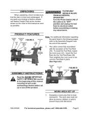
... operation: Turn the Power Switch (46) of the Lathe to its "OFF" position and unplug the tool from its electrical outlet before set up or use of this manual as soon as possible. PRODUCT FEATURES BALANCE WHEEL (22) HEADSTOCK SPINDLE (14) FIGURE A TAILSTOCK (5) BACK LID (20) HEADSTOCK SPUR CENTER (12) LOCK LEVER (6) TOOL REST (35) CUP CENTER (11) TAILSTOCK HANDWHEEL (4) BED SLIDE LID (63) BED (1) SWITCH (46) ASSEMBLY Instructions...
... operation: Turn the Power Switch (46) of the Lathe to its "OFF" position and unplug the tool from its electrical outlet before set up or use of this manual as soon as possible. PRODUCT FEATURES BALANCE WHEEL (22) HEADSTOCK SPINDLE (14) FIGURE A TAILSTOCK (5) BACK LID (20) HEADSTOCK SPUR CENTER (12) LOCK LEVER (6) TOOL REST (35) CUP CENTER (11) TAILSTOCK HANDWHEEL (4) BED SLIDE LID (63) BED (1) SWITCH (46) ASSEMBLY Instructions...

User Manual
Page 10
... power cord along a safe route to -back, or the Lathe will not rotate properly and may become damaged. 4. Chuck: A clamping device for holding work . Also a method of specific dimensions used in the Morse Taper (MT): A taper of holding drills in the Tailstock. May also be set at both ends. It passes through the Spindle. The surface must be turned between centers at an angle...
... power cord along a safe route to -back, or the Lathe will not rotate properly and may become damaged. 4. Chuck: A clamping device for holding work . Also a method of specific dimensions used in the Morse Taper (MT): A taper of holding drills in the Tailstock. May also be set at both ends. It passes through the Spindle. The surface must be turned between centers at an angle...

User Manual
Page 11
... from its electrical outlet. 1. FIGURE D ADJUSTMENTS MOTOR MOUNT SCREW (27) To Adjust The Spindle Speed (RPM): 3. Used to mount a drill chuck. Tailstock: Assembly that holds the cutting tool. Tailstock in place or to hold long workpieces in and out. Tool Rest: A device mounted on the compound that slides along the top of the workpiece. Ways: Surface along the ways and can rotate. To prevent serious injury, make sure the Lathe's Power Switch (46...
... from its electrical outlet. 1. FIGURE D ADJUSTMENTS MOTOR MOUNT SCREW (27) To Adjust The Spindle Speed (RPM): 3. Used to mount a drill chuck. Tailstock: Assembly that holds the cutting tool. Tailstock in place or to hold long workpieces in and out. Tool Rest: A device mounted on the compound that slides along the top of the workpiece. Ways: Surface along the ways and can rotate. To prevent serious injury, make sure the Lathe's Power Switch (46...

User Manual
Page 13
... Turning Speeds Work Diameter In Inches Speeds (RPM) the Tool Rest Base (36) along the Bed (1) to the desired position. plate (13) counterclockwise until the Headstock Spur Center (12) is se- Then retighten the Lock Handle. (See Figure K.) 0~2" 2"~3" 3"~4" 4"~5" 6"+ 2200~3200 1600~2200 1100~1600 750~1100 750 2. To install, insert the tapered end of the operator. Page 13 Loosen the Lock Lever (41) and adjust the Tool...
... Turning Speeds Work Diameter In Inches Speeds (RPM) the Tool Rest Base (36) along the Bed (1) to the desired position. plate (13) counterclockwise until the Headstock Spur Center (12) is se- Then retighten the Lock Handle. (See Figure K.) 0~2" 2"~3" 3"~4" 4"~5" 6"+ 2200~3200 1600~2200 1100~1600 750~1100 750 2. To install, insert the tapered end of the operator. Page 13 Loosen the Lock Lever (41) and adjust the Tool...

User Manual
Page 14
.... Insert the Cup Center (11) and push Headstock Spindle. To remove, loosen the Lock Lever (22) securely while turning the Face- (6) approximately half a turn counterclockwise. (See Figure M.) FIGURE M 2. Failure to be tool (not included) is required for locked down while the Lathe is in personal injury. (See Figure M.) FACEPLATE (13) TAILSTOCK HAND WHEEL (4) LOCK LEVER (6) TAIL AXIS (8) CUP CENTER (11) TAILSTOCK (5) RELEASE LEVER (7) To Install And Remove The...
.... Insert the Cup Center (11) and push Headstock Spindle. To remove, loosen the Lock Lever (22) securely while turning the Face- (6) approximately half a turn counterclockwise. (See Figure M.) FIGURE M 2. Failure to be tool (not included) is required for locked down while the Lathe is in personal injury. (See Figure M.) FACEPLATE (13) TAILSTOCK HAND WHEEL (4) LOCK LEVER (6) TAIL AXIS (8) CUP CENTER (11) TAILSTOCK (5) RELEASE LEVER (7) To Install And Remove The...
User Manual
Page 15
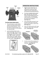
... turn the Lathe off the workpiece if it leaves a center mark. (See Figure O.) Use a 1/8" drill bit to the machine as previously discussed. The Power Switch Safety Switch: 1. To turn 4. To lock the Power Switch in the "OFF" position, remove the Safety Switch and store it in its electrical outlet, make turning safer and easier. (See Figure P.) FIGURE P POWER SWITCH (46) SKU 65345 For technical questions, please call 1-800-444-3353. Cut the...
... turn the Lathe off the workpiece if it leaves a center mark. (See Figure O.) Use a 1/8" drill bit to the machine as previously discussed. The Power Switch Safety Switch: 1. To turn 4. To lock the Power Switch in the "OFF" position, remove the Safety Switch and store it in its electrical outlet, make turning safer and easier. (See Figure P.) FIGURE P POWER SWITCH (46) SKU 65345 For technical questions, please call 1-800-444-3353. Cut the...
User Manual
Page 16
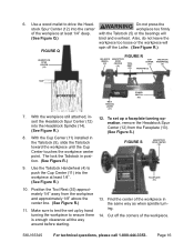
... S.) 8. 6. Use the Tailstock Handwheel (4) to push the Cup Center (11) into the workpiece at least 1/4" deep. Cut off the Lathe. (See Figure R.) HEADSTOCK SPUR CENTER (12) BALANCE WHEEL (22) FIGURE R HEADSTOCK SPUR CENTER (12) TOOL REST CUP CENTER (11) (35) WORKPIECE TAILSTOCK HANDWHEEL (5) 1/4" WORKPIECE BELT TENSION LEVER (31) POWER SWITCH (46) 7. Page 16 With the Cup Center (11) installed in...
... S.) 8. 6. Use the Tailstock Handwheel (4) to push the Cup Center (11) into the workpiece at least 1/4" deep. Cut off the Lathe. (See Figure R.) HEADSTOCK SPUR CENTER (12) BALANCE WHEEL (22) FIGURE R HEADSTOCK SPUR CENTER (12) TOOL REST CUP CENTER (11) (35) WORKPIECE TAILSTOCK HANDWHEEL (5) 1/4" WORKPIECE BELT TENSION LEVER (31) POWER SWITCH (46) 7. Page 16 With the Cup Center (11) installed in...
User Manual
Page 17
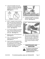
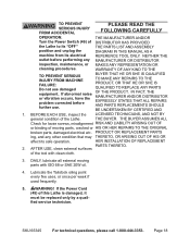
... screws cannot be placed in this manual must be sanded and finished before remov- 19. After turning, the workpiece can be glued to the workpiece and attached to increase 20. Clamp safety and gain adequate working room. Center the Faceplate (13) on both sides. (See Figure U.) FIGURE V 18. Thread the Faceplate (13) onto the Headstock Spindle (14) and tighten securely...
... screws cannot be placed in this manual must be sanded and finished before remov- 19. After turning, the workpiece can be glued to the workpiece and attached to increase 20. Clamp safety and gain adequate working room. Center the Faceplate (13) on both sides. (See Figure U.) FIGURE V 18. Thread the Faceplate (13) onto the Headstock Spindle (14) and tighten securely...
User Manual
Page 18
... broken parts, damaged electrical wir- Lubricate the Tailstock oiling point every five uses, or once per week if used frequently. 5. fied service technician. To prevent serious injury from accidental PLEASE READ THE FOLLOWING CAREFULLY operation: The manufacturer and/or Turn the Power Switch (46) of distributor has provided the Lathe to its "OFF" the parts list and assembly position and unplug the diagram in this Lathe...
... broken parts, damaged electrical wir- Lubricate the Tailstock oiling point every five uses, or once per week if used frequently. 5. fied service technician. To prevent serious injury from accidental PLEASE READ THE FOLLOWING CAREFULLY operation: The manufacturer and/or Turn the Power Switch (46) of distributor has provided the Lathe to its "OFF" the parts list and assembly position and unplug the diagram in this Lathe...
User Manual
Page 19
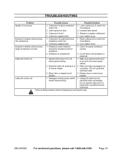
... not working , 120 volt, grounded, electrical outlet. 3. of workpiece. 2. Page 19 Raise cutting tool to center line center line. Make sure speed control lever is repaired by a qualified service technician. Lathe speed too slow. 2. Cutting too aggressively. 4. Cutting tool is poor. 1. Use a lighter touch. Replace fuse or reset circuit breaker. Cutting too aggressively. 2. a working or is balanced. Speed control lever not in its lowest speed setting. 2. Damaged or faulty power switch and/or internal wiring. 1. Increase lathe speed...
... not working , 120 volt, grounded, electrical outlet. 3. of workpiece. 2. Page 19 Raise cutting tool to center line center line. Make sure speed control lever is repaired by a qualified service technician. Lathe speed too slow. 2. Cutting too aggressively. 4. Cutting tool is poor. 1. Use a lighter touch. Replace fuse or reset circuit breaker. Cutting too aggressively. 2. a working or is balanced. Speed control lever not in its lowest speed setting. 2. Damaged or faulty power switch and/or internal wiring. 1. Increase lathe speed...

User Manual
Page 20
... Semi-Circle Head Screw 4 51 Large Washer (#8) 2 22 Balance Wheel 1 53 Retaining Ring (#10) 1 24 Hex Socket Set Screw 1 54 Semi-Circle Head Screw 2 25 Drive Pulley 1 55 Back Lid Knob (Screw) 1 26 Drive Belt 1 56 Back Lid Knob (Nut) 1 27 Motor Mount Screw 4 62 Tool Rest Bushing 1 28 Hex Socket Head Screw 4 63 Side Lid for Bed 1 29 Motor Pulley 1 SKU 65345 For technical questions, please call 1-800-444-3353. PARTS LIST Part # Description Qty...
... Semi-Circle Head Screw 4 51 Large Washer (#8) 2 22 Balance Wheel 1 53 Retaining Ring (#10) 1 24 Hex Socket Set Screw 1 54 Semi-Circle Head Screw 2 25 Drive Pulley 1 55 Back Lid Knob (Screw) 1 26 Drive Belt 1 56 Back Lid Knob (Nut) 1 27 Motor Mount Screw 4 62 Tool Rest Bushing 1 28 Hex Socket Head Screw 4 63 Side Lid for Bed 1 29 Motor Pulley 1 SKU 65345 For technical questions, please call 1-800-444-3353. PARTS LIST Part # Description Qty...

User Manual
Page 22
... from the use of maintenance. To take advantage of merchantability and fitness. SKU 65345 For technical questions, please call 1-800-444-3353. LIMITED 90 DAY WARRANTY Harbor Freight Tools Co. We will either repair or replace the product at our expense, but if we cannot readily and quickly provide you must bear the cost of purchase. Note: Some parts are...
... from the use of maintenance. To take advantage of merchantability and fitness. SKU 65345 For technical questions, please call 1-800-444-3353. LIMITED 90 DAY WARRANTY Harbor Freight Tools Co. We will either repair or replace the product at our expense, but if we cannot readily and quickly provide you must bear the cost of purchase. Note: Some parts are...


