

User Manual
Page 2
... risks of the dust or fumes. 3. Page 2 For technical questions, please call 1-888-866-5797. Cluttered benches and dark areas increase the risks of Contents Safetye 2 Specifications 6 Setup 7 Operationa 10 Maintenancei 12 Parts List and Diagram 14 Warranty 16 Safety Setup Operation WARNING SYMBOLS AND DEFINITIONS This is used to alert you to potential personal injury hazards. Table of electric shock, fire, and...
... risks of the dust or fumes. 3. Page 2 For technical questions, please call 1-888-866-5797. Cluttered benches and dark areas increase the risks of Contents Safetye 2 Specifications 6 Setup 7 Operationa 10 Maintenancei 12 Parts List and Diagram 14 Warranty 16 Safety Setup Operation WARNING SYMBOLS AND DEFINITIONS This is used to alert you to potential personal injury hazards. Table of electric shock, fire, and...
User Manual
Page 3
... any residual air pressure, and release the throttle and/or turn the tool on or off before turning the tool on . 4. The correct tool will do the job better and safer at all times. Disconnect the tool from moving parts, breakage of being caught in the hands of binding and is off . When servicing a tool, use common sense when operating the tool. Page 3 Remove adjusting keys and wrenches before connecting...
... any residual air pressure, and release the throttle and/or turn the tool on or off before turning the tool on . 4. The correct tool will do the job better and safer at all times. Disconnect the tool from moving parts, breakage of being caught in the hands of binding and is off . When servicing a tool, use common sense when operating the tool. Page 3 Remove adjusting keys and wrenches before connecting...
User Manual
Page 4
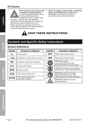
... per square inch of pressure ft-lb Foot-pounds of Respiratory Injury. Safety Setup Air Source 1. Never connect to the rated air pressure or within the rated pressure range as an air source for the tool. Never use oxygen, carbon dioxide, combustible gases or any bottled gas as marked on the tool. SAVE THESE INSTRUCTIONS. Symbols and Specific Safety Instructions Symbol Definitions Symbol Property or statement no No-load speed...
... per square inch of pressure ft-lb Foot-pounds of Respiratory Injury. Safety Setup Air Source 1. Never connect to the rated air pressure or within the rated pressure range as an air source for the tool. Never use oxygen, carbon dioxide, combustible gases or any bottled gas as marked on the tool. SAVE THESE INSTRUCTIONS. Symbols and Specific Safety Instructions Symbol Definitions Symbol Property or statement no No-load speed...
User Manual
Page 5
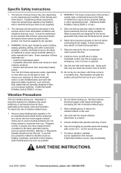
... this tool. Do not smoke during operation. 7. Do not lay the tool down until it ). To reduce your control. Safety Setup Specific Safety Instructions 1. If abnormal vibration occurs, stop . Nicotine reduces the blood supply to filter out microscopic particles. (California Health & Safety Code § 25249.5, et seq.) 4. Operation Maintenance Item 63061 62835 For technical questions, please call 1-888-866-5797. Use tools with only one hand can...
... this tool. Do not smoke during operation. 7. Do not lay the tool down until it ). To reduce your control. Safety Setup Specific Safety Instructions 1. If abnormal vibration occurs, stop . Nicotine reduces the blood supply to filter out microscopic particles. (California Health & Safety Code § 25249.5, et seq.) 4. Operation Maintenance Item 63061 62835 For technical questions, please call 1-888-866-5797. Use tools with only one hand can...

User Manual
Page 6
Item 63061 62835 Safety Functional Description Specifications Maximum Air Pressure Air Inlet Average Air Consumption Drive Size (62835) Drive Size (63061) 90 PSI 1/4″ -18 NPT 6 CFM @ 90 PSI 1/2″ 3/8″ Components and Controls Anvil Trigger Air Inlet Regulator Knob Setup Operation Maintenance Page 6 For technical questions, please call 1-888-866-5797.
Item 63061 62835 Safety Functional Description Specifications Maximum Air Pressure Air Inlet Average Air Consumption Drive Size (62835) Drive Size (63061) 90 PSI 1/4″ -18 NPT 6 CFM @ 90 PSI 1/2″ 3/8″ Components and Controls Anvil Trigger Air Inlet Regulator Knob Setup Operation Maintenance Page 6 For technical questions, please call 1-888-866-5797.
User Manual
Page 7
... to the Assembly Diagram near the end of this tool. 1. Turn the tool's switch to set the right pressure range. 7. Adjust the pressure gradually, while checking the air output gauge to the off position to Operation section for this manual. Inspect the air connections for best service, as a coupler plug and quick coupler, will not be a ball valve because it controls the air supply even if the air hose is...
... to the Assembly Diagram near the end of this tool. 1. Turn the tool's switch to set the right pressure range. 7. Adjust the pressure gradually, while checking the air output gauge to the off position to Operation section for this manual. Inspect the air connections for best service, as a coupler plug and quick coupler, will not be a ball valve because it controls the air supply even if the air hose is...
User Manual
Page 8
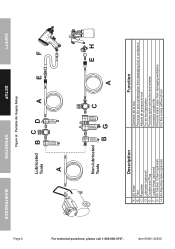
Safety Setup Operation Maintenance Page 8 Figure A: Portable Air Supply Setup Lubricated Tools Bc D A E F A For technical questions, please call 1-888-866-5797. Non-lubricated Tools c EH BG A Description A Air Hose B Filter C Regulator D Lubricator (optional) E Coupler and Plug F Leader Hose (optional) G Air Cleaner / Dryer (optional) H Air Adjusting Valve (optional) Function Connects air to tool Prevents dirt and condensation from damaging tool or workpiece Adjusts air pressure to tool For air tool lubrication Provides quick connection and release Increases coupler...
Safety Setup Operation Maintenance Page 8 Figure A: Portable Air Supply Setup Lubricated Tools Bc D A E F A For technical questions, please call 1-888-866-5797. Non-lubricated Tools c EH BG A Description A Air Hose B Filter C Regulator D Lubricator (optional) E Coupler and Plug F Leader Hose (optional) G Air Cleaner / Dryer (optional) H Air Adjusting Valve (optional) Function Connects air to tool Prevents dirt and condensation from damaging tool or workpiece Adjusts air pressure to tool For air tool lubrication Provides quick connection and release Increases coupler...
User Manual
Page 9
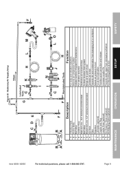
... moisture from system Brings air to point of use Connects air to tool Prevents dirt and condensation from damaging tool or workpiece Adjusts air pressure to tool For air tool lubrication Provides quick connection and release Increases coupler life Prevents water vapor from damaging workpiece For fine tuning airflow at tool Page 9 Maintenance Operation Setup Safety Item 63061 62835 Figure B: Stationary Air Supply Setup Slope Lubricated G Tools c J K H L M F cD E For technical questions...
... moisture from system Brings air to point of use Connects air to tool Prevents dirt and condensation from damaging tool or workpiece Adjusts air pressure to tool For air tool lubrication Provides quick connection and release Increases coupler life Prevents water vapor from damaging workpiece For fine tuning airflow at tool Page 9 Maintenance Operation Setup Safety Item 63061 62835 Figure B: Stationary Air Supply Setup Slope Lubricated G Tools c J K H L M F cD E For technical questions...
User Manual
Page 10
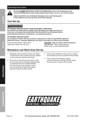
... the tool, and release the throttle and/or turn the switch to reach the work area must not allow free movement while working. 3. Connect an appropriate, impact rated square drive socket onto the anvil. The hose must not be long enough to its off the tool, detach the air supply, safely discharge any problems are found, do not use , looking for damaged, loose, and missing parts. Setup Operation Maintenance...
... the tool, and release the throttle and/or turn the switch to reach the work area must not allow free movement while working. 3. Connect an appropriate, impact rated square drive socket onto the anvil. The hose must not be long enough to its off the tool, detach the air supply, safely discharge any problems are found, do not use , looking for damaged, loose, and missing parts. Setup Operation Maintenance...
User Manual
Page 11
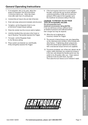
... vary depending on top of continual use. 2. To tighten, set the Regulator Knob to the Airline Connection before use . To prevent accidents, turn off the tool, detach the air supply, safely discharge any residual air pressure in the tool, and release the throttle and/or turn the switch to the air inlet of children's reach. If an automatic oiler is tightened or loosened, release the Trigger. 11. Safety General Operating Instructions 1.
... vary depending on top of continual use. 2. To tighten, set the Regulator Knob to the Airline Connection before use . To prevent accidents, turn off the tool, detach the air supply, safely discharge any residual air pressure in the tool, and release the throttle and/or turn the switch to the air inlet of children's reach. If an automatic oiler is tightened or loosened, release the Trigger. 11. Safety General Operating Instructions 1.
User Manual
Page 12
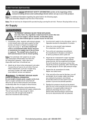
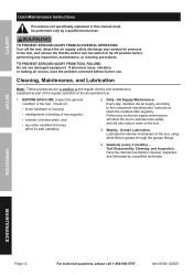
... before further use damaged equipment. Safety User‑Maintenance Instructions Procedures not specifically explained in this manual must be performed only by a qualified technician. TO PREVENT SERIOUS INJURY FROM ACCIDENTAL OPERATION: Turn off the tool, detach the air supply, safely discharge any residual air pressure in addition to operate more safely and will also reduce wear on the tool. 3. Daily - Item 63061 62835 Cleaning, Maintenance, and Lubrication...
... before further use damaged equipment. Safety User‑Maintenance Instructions Procedures not specifically explained in this manual must be performed only by a qualified technician. TO PREVENT SERIOUS INJURY FROM ACCIDENTAL OPERATION: Turn off the tool, detach the air supply, safely discharge any residual air pressure in addition to operate more safely and will also reduce wear on the tool. 3. Daily - Item 63061 62835 Cleaning, Maintenance, and Lubrication...
User Manual
Page 13
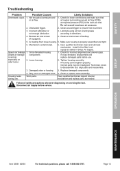
... free movement. 3. If housing cannot tighten properly, internal parts may be misaligned. Setup Operation Maintenance Item 63061 62835 For technical questions, please call 1-888-866-5797. Do not exceed maximum air pressure. 2. Incorrect lubrication or not enough lubrication. 3. Lubricate using air tool oil and grease according to disassemble tool, align parts and reassemble. 3. Blocked air inlet screen (if equipped). 4. is properly assembled and tight. 6. Technician needs to directions. 4. Worn parts...
... free movement. 3. If housing cannot tighten properly, internal parts may be misaligned. Setup Operation Maintenance Item 63061 62835 For technical questions, please call 1-888-866-5797. Do not exceed maximum air pressure. 2. Incorrect lubrication or not enough lubrication. 3. Lubricate using air tool oil and grease according to disassemble tool, align parts and reassemble. 3. Blocked air inlet screen (if equipped). 4. is properly assembled and tight. 6. Technician needs to directions. 4. Worn parts...
User Manual
Page 14
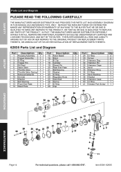
... OUT OF HIS OR HER INSTALLATION OF REPLACEMENT PARTS THERETO. 62835 Parts List and Diagram Part Description Qty Part Description Qty 1 Housing Assembly 1 15 Rotor Blade 7 2 Trigger Assembly 1 16 Rotor 1 3 O Ring 1 17 E Clip 1 4 Trigger Pin 1 18 Cylinder 1 5 Oil Seal 1 19 Dowel Pin 1 6 Valve Stem 1 20 Rear End Plate 1 7 Throttle Valve 1 21 Ball Bearing 1 8 Throttle Valve Spring 1 22 Gasket 1 9 Exhaust Deflector 1 23 O Ring 1 10 Air Inlet 1 24 Regulator Knob 1 11 Washer 1 25 Steel Ball 1 12...
... OUT OF HIS OR HER INSTALLATION OF REPLACEMENT PARTS THERETO. 62835 Parts List and Diagram Part Description Qty Part Description Qty 1 Housing Assembly 1 15 Rotor Blade 7 2 Trigger Assembly 1 16 Rotor 1 3 O Ring 1 17 E Clip 1 4 Trigger Pin 1 18 Cylinder 1 5 Oil Seal 1 19 Dowel Pin 1 6 Valve Stem 1 20 Rear End Plate 1 7 Throttle Valve 1 21 Ball Bearing 1 8 Throttle Valve Spring 1 22 Gasket 1 9 Exhaust Deflector 1 23 O Ring 1 10 Air Inlet 1 24 Regulator Knob 1 11 Washer 1 25 Steel Ball 1 12...
User Manual
Page 15
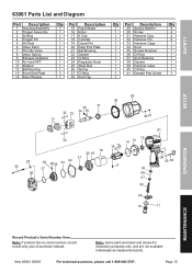
Page 15 Safety Setup 63061 Parts List and Diagram Part Description Qty Part Description Qty Part Description Qty 1 Housing Assembly 1 15 Rotor Blade 7 29 Spring Washer 4 2 Trigger Assembly 1 16 Rotor 1 30 Screw 4 3 O-Ring 1 17 E Clip 1 31 Hammer Dog 2 4 Trigger Pin 1 18 Cylinder 1 32 Hammer Pin 2 5 Oil Seal 1 19 Dowel Pin 1 33 Hammer Cage 1 6 Valve Stem 1 20 Rear End Plate 1 34 Anvil 1 7 Throttle Valve 1 21 Ball Bearing 1 35 Socket Retainer 1 8 Valve Spring 1 22 Gasket 1 36 O-Ring 1 9 Exhaust Deflector 1 23 O-Ring 1 37...
Page 15 Safety Setup 63061 Parts List and Diagram Part Description Qty Part Description Qty Part Description Qty 1 Housing Assembly 1 15 Rotor Blade 7 29 Spring Washer 4 2 Trigger Assembly 1 16 Rotor 1 30 Screw 4 3 O-Ring 1 17 E Clip 1 31 Hammer Dog 2 4 Trigger Pin 1 18 Cylinder 1 32 Hammer Pin 2 5 Oil Seal 1 19 Dowel Pin 1 33 Hammer Cage 1 6 Valve Stem 1 20 Rear End Plate 1 34 Anvil 1 7 Throttle Valve 1 21 Ball Bearing 1 35 Socket Retainer 1 8 Valve Spring 1 22 Gasket 1 36 O-Ring 1 9 Exhaust Deflector 1 23 O-Ring 1 37...
User Manual
Page 16
... apply to us with a replacement. This warranty does not apply to damage due directly or indirectly, to misuse, abuse, negligence or accidents, repairs or alterations outside our facilities, criminal activity, improper installation, normal wear and tear, or to persons or property, or for the period of 90 days from the use of returning the product. THIS...
... apply to us with a replacement. This warranty does not apply to damage due directly or indirectly, to misuse, abuse, negligence or accidents, repairs or alterations outside our facilities, criminal activity, improper installation, normal wear and tear, or to persons or property, or for the period of 90 days from the use of returning the product. THIS...


