
User Manual
Page 1
MODEL: LT32F6 LTF37F6 LTF42F6 LCD TV RECEIVER USER MANUAL Please read this manual carefully before using your television and keep this manual in a good place for future reference.
MODEL: LT32F6 LTF37F6 LTF42F6 LCD TV RECEIVER USER MANUAL Please read this manual carefully before using your television and keep this manual in a good place for future reference.
User Manual
Page 5
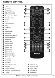
... 14 15 16 17 18 19 20 21 36 Channel List 37 Screen Button 38 Sleep Button 39 Sound Mode 40 No function | HD Ready LCD TV | User Manual 40 39 38 37 36 35 34 33 32 31 30 29 28 27 26 25 24 23 22 p.03
... 14 15 16 17 18 19 20 21 36 Channel List 37 Screen Button 38 Sleep Button 39 Sound Mode 40 No function | HD Ready LCD TV | User Manual 40 39 38 37 36 35 34 33 32 31 30 29 28 27 26 25 24 23 22 p.03

User Manual
Page 6
Battery Compartment Cover HTR-D06A 2 x AAA Battery fig.1 fig. 2 p.04 | HD Ready LCD TV | User Manual Unclip the Battery Cover from remote control handset when it is not to be used and new batteries in the device. • Replace ...
Battery Compartment Cover HTR-D06A 2 x AAA Battery fig.1 fig. 2 p.04 | HD Ready LCD TV | User Manual Unclip the Battery Cover from remote control handset when it is not to be used and new batteries in the device. • Replace ...
User Manual
Page 7
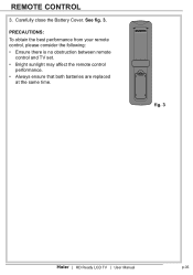
HTR-D06A fig. 3 | HD Ready LCD TV | User Manual p.05 PRECAUTIONS: To obtain the best performance from your remote control, please consider the following: • Ensure there is no obstruction between remote control and TV set. • Bright sunlight may affect the remote control performance. • Always ensure that both batteries are replaced at the same time. Carefully close the Battery Cover. REMOTE CONTROL 3. See fig. 3.
HTR-D06A fig. 3 | HD Ready LCD TV | User Manual p.05 PRECAUTIONS: To obtain the best performance from your remote control, please consider the following: • Ensure there is no obstruction between remote control and TV set. • Bright sunlight may affect the remote control performance. • Always ensure that both batteries are replaced at the same time. Carefully close the Battery Cover. REMOTE CONTROL 3. See fig. 3.
User Manual
Page 8
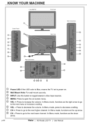
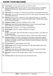
... as the up arrow. 8 CH -: Press to go to decrease the volume. In Menu mode, functions as the down arrow. p.06 | HD Ready LCD TV | User Manual KNOW YOUR MACHINE 1 x LCD TV Front View Control Panel 3 4 5 6 7 8 9 1 2 25 Rear Connections 24 23 Side Connections 10 Rear View 11 12 13 14 15 16 17 22... 21 20 19 18 1 Power LED: If the LED color is Blue, means the TV set is power on. 2 Wall Mount Hole: For wall mount...
... as the up arrow. 8 CH -: Press to go to decrease the volume. In Menu mode, functions as the down arrow. p.06 | HD Ready LCD TV | User Manual KNOW YOUR MACHINE 1 x LCD TV Front View Control Panel 3 4 5 6 7 8 9 1 2 25 Rear Connections 24 23 Side Connections 10 Rear View 11 12 13 14 15 16 17 22... 21 20 19 18 1 Power LED: If the LED color is Blue, means the TV set is power on. 2 Wall Mount Hole: For wall mount...
User Manual
Page 9
...Connect to VGA analogue signals sources. PC audio supports 3.5mm Jack. 25 AC Power Cord: Connect the power cord into the power outlet. | HD Ready LCD TV | User Manual p.07 SCART 2: Half SCART, which transmits S-Video or CVBS in and CVBS monitor out. 19 Component Input: The YPbPr video signal can...PC Audio Input: PC audio supports 3.5mm Jack. 21 SPDIF Output: SPDIF is in COMMON INTERFACE slot of the set. Please refer to your LCD TV on/off. 10 Common Interface Slot: Function when PC Card or ExpressCard is highly recommended for high quality digital sound output. 22 SERVICE: For ...
...Connect to VGA analogue signals sources. PC audio supports 3.5mm Jack. 25 AC Power Cord: Connect the power cord into the power outlet. | HD Ready LCD TV | User Manual p.07 SCART 2: Half SCART, which transmits S-Video or CVBS in and CVBS monitor out. 19 Component Input: The YPbPr video signal can...PC Audio Input: PC audio supports 3.5mm Jack. 21 SPDIF Output: SPDIF is in COMMON INTERFACE slot of the set. Please refer to your LCD TV on/off. 10 Common Interface Slot: Function when PC Card or ExpressCard is highly recommended for high quality digital sound output. 22 SERVICE: For ...
User Manual
Page 10
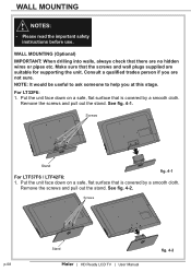
Consult a qualified trades person if you at this stage. For LT32F6: 1. Screws Stand fig. 4-1 For LTF37F6 / LTF42F6: 1. Screws Stand fig. 4-2 p.08 | HD Ready LCD TV | User Manual NOTE: It would be useful to ask someone to help you are no hidden wires or pipes etc. Make sure that is covered ...
Consult a qualified trades person if you at this stage. For LT32F6: 1. Screws Stand fig. 4-1 For LTF37F6 / LTF42F6: 1. Screws Stand fig. 4-2 p.08 | HD Ready LCD TV | User Manual NOTE: It would be useful to ask someone to help you are no hidden wires or pipes etc. Make sure that is covered ...

User Manual
Page 11
For the Wall Bracket - Screws fig. 4-3 3. See fig. 5. 2 fig. 5 4. See fig. 4-3. Usie two screws to secure the cover back to the user instructions supplied with the wall bracket (not included). Refer to the bottom of the TV. Use 4 Wall Mount Holes 2 and screws (not included) to mount the TV on the bracket (not included). W H TV Screen Size (inches) 32" 37" VESA-Compatible Wall bracket (W x H mm) Screw Type 200 x 200 mm Metric 6 x 10 mm 200 x 200 mm Metric 6 x 10 mm 42" 400 x 200 mm Metric 6 x 10 mm | HD Ready LCD TV | User Manual p.09 WALL MOUNTING 2.
For the Wall Bracket - Screws fig. 4-3 3. See fig. 5. 2 fig. 5 4. See fig. 4-3. Usie two screws to secure the cover back to the user instructions supplied with the wall bracket (not included). Refer to the bottom of the TV. Use 4 Wall Mount Holes 2 and screws (not included) to mount the TV on the bracket (not included). W H TV Screen Size (inches) 32" 37" VESA-Compatible Wall bracket (W x H mm) Screw Type 200 x 200 mm Metric 6 x 10 mm 200 x 200 mm Metric 6 x 10 mm 42" 400 x 200 mm Metric 6 x 10 mm | HD Ready LCD TV | User Manual p.09 WALL MOUNTING 2.
User Manual
Page 12
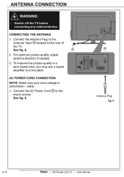
... 1. To improve the picture quality in a poor signal area, you may use a signal amplifier (not included). See fig. 6. 16 Antenna Plug fig. 6 p.10 | HD Ready LCD TV | User Manual Connect the AC Power Cord 25 to the Antenna Input 16 located at the rear of the...
... 1. To improve the picture quality in a poor signal area, you may use a signal amplifier (not included). See fig. 6. 16 Antenna Plug fig. 6 p.10 | HD Ready LCD TV | User Manual Connect the AC Power Cord 25 to the Antenna Input 16 located at the rear of the...
User Manual
Page 13
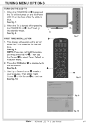
...ol Português Nederlands fig. 9 Back Select Next EXIT Exit fig. 10 | HD Ready LCD TV | User Manual p.11 This display will appear on the screen when the TV is turned on the front of the TV will go into standby mode. See fig. 8. 1 FIRST TIME INSTALLATION 1. See fig. ...9. Use Up or Down Cursor 31 to select Reset Default in Features menu. 2. Initial Setup Please select your language. TUNING MENU OPTIONS TURN ON THE LCD-TV 1. See fig. 8. 3. See fig. 10. 1 Vol 11 Initial Setup Welcome to start the wizard. 9 fig. 7 31 fig. 8 WELCOME! See fig. 7. 2. When ...
...ol Português Nederlands fig. 9 Back Select Next EXIT Exit fig. 10 | HD Ready LCD TV | User Manual p.11 This display will appear on the screen when the TV is turned on the front of the TV will go into standby mode. See fig. 8. 1 FIRST TIME INSTALLATION 1. See fig. ...9. Use Up or Down Cursor 31 to select Reset Default in Features menu. 2. Initial Setup Please select your language. TUNING MENU OPTIONS TURN ON THE LCD-TV 1. See fig. 8. 3. See fig. 10. 1 Vol 11 Initial Setup Welcome to start the wizard. 9 fig. 7 31 fig. 8 WELCOME! See fig. 7. 2. When ...
User Manual
Page 14
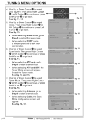
... 6875 999 31 fig. 11 fig. 12 fig. 13 fig. 14 fig. 15 fig. 16 / Select ENTER Next EXIT Exit fig. 17 p.12 | HD Ready LCD TV | User Manual See fig. 16, 17. Use Up or Down Cursor 31 to start channel scan. • When selecting Cable, the Scan Mode configuration screen...
... 6875 999 31 fig. 11 fig. 12 fig. 13 fig. 14 fig. 15 fig. 16 / Select ENTER Next EXIT Exit fig. 17 p.12 | HD Ready LCD TV | User Manual See fig. 16, 17. Use Up or Down Cursor 31 to start channel scan. • When selecting Cable, the Scan Mode configuration screen...
User Manual
Page 15
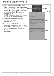
... scan could be performed in Menu. See fig. 21. EXIT Exit Completed 31 fig. 18 fig. 19 fig. 20 Back fig. 21 | HD Ready LCD TV | User Manual p.13 Use Up or Down Cursor 31 to select Scan to start scan or select Skip Scan to complete. TUNING MENU OPTIONS Vol...] to go back. Then press Right 12 Cursor 31 or OK Button 12 to continue or press Left Cursor 31 to exit the wizard. The TV will be performaed in Menu. 9. Analogue Channels: 0 Channel Scan Back Select 4% Next Initial Setup Congratulations !! Completed Initial Setup. Channel Scan Scan Skip Scan Back...
... scan could be performed in Menu. See fig. 21. EXIT Exit Completed 31 fig. 18 fig. 19 fig. 20 Back fig. 21 | HD Ready LCD TV | User Manual p.13 Use Up or Down Cursor 31 to select Scan to start scan or select Skip Scan to complete. TUNING MENU OPTIONS Vol...] to go back. Then press Right 12 Cursor 31 or OK Button 12 to continue or press Left Cursor 31 to exit the wizard. The TV will be performaed in Menu. 9. Analogue Channels: 0 Channel Scan Back Select 4% Next Initial Setup Congratulations !! Completed Initial Setup. Channel Scan Scan Skip Scan Back...
User Manual
Page 16
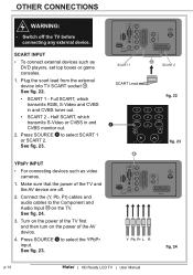
... any external device. Connect the (Y, Pb, Pr) cables and audio cables to select SCART 1 or SCART 2. Plug the scart lead from the external device into TV SCART socket 18 . Half SCART, which transmits RGB, S-Video and CVBS in and CVBS monitor out. 2. Switch off . 2. See fig. 22. • SCART 1 -... 4. See fig. 24. 3. See fig. 23. 18 SCART 1 SCART Lead 8 Vol 19 Y Pb Pr L R SCART 2 fig. 22 fig. 23 fig. 24 p.14 | HD Ready LCD TV | User Manual YPbPr INPUT • For connecting devices such as DVD players, set top boxes or game consoles. 1. See fig. 23. Press SOURCE 8 to select...
... any external device. Connect the (Y, Pb, Pr) cables and audio cables to select SCART 1 or SCART 2. Plug the scart lead from the external device into TV SCART socket 18 . Half SCART, which transmits RGB, S-Video and CVBS in and CVBS monitor out. 2. Switch off . 2. See fig. 22. • SCART 1 -... 4. See fig. 24. 3. See fig. 23. 18 SCART 1 SCART Lead 8 Vol 19 Y Pb Pr L R SCART 2 fig. 22 fig. 23 fig. 24 p.14 | HD Ready LCD TV | User Manual YPbPr INPUT • For connecting devices such as DVD players, set top boxes or game consoles. 1. See fig. 23. Press SOURCE 8 to select...

User Manual
Page 17
...Press SOURCE 8 to select the PC input. Connect the audio cable (not supplied) to external equipment operating guide.) fig. 25 fig. 26 | HD Ready LCD TV | User Manual p.15 See fig. 25. 3. Vol 1. Operate the corresponding external equipment. (Refer to Audio Input 20 on the back of the...ensure both devices are switched off before 8 connection. See fig. 26. 3. Connect the D type 15-pin VGA 24 interface cable (not supplied) to the TV HDMI Input 23 . Connect the cable from the HDMI devices to VGA 23 Input 24 . See fig. 25. 2. OTHER CONNECTIONS VGA INPUT • You ...
...Press SOURCE 8 to select the PC input. Connect the audio cable (not supplied) to external equipment operating guide.) fig. 25 fig. 26 | HD Ready LCD TV | User Manual p.15 See fig. 25. 3. Vol 1. Operate the corresponding external equipment. (Refer to Audio Input 20 on the back of the...ensure both devices are switched off before 8 connection. See fig. 26. 3. Connect the D type 15-pin VGA 24 interface cable (not supplied) to the TV HDMI Input 23 . Connect the cable from the HDMI devices to VGA 23 Input 24 . See fig. 25. 2. OTHER CONNECTIONS VGA INPUT • You ...

User Manual
Page 18
Make sure that the power of the TV and the AV device are off. 2. See fig. 27. 4. Connect the video cables from the AV device's output jacks to the Video Input 12 . OTHER CONNECTIONS AV INPUT • For connecting an AV device. 1. Turn on the TV first, and then turn on the AV device. 5. fig. 27 8 Vol fig. 28 p.16 | HD Ready LCD TV | User Manual Connect the audio cables from the AV device's output jacks to the Audio Input 11 . Press SOURCE 8 to select the AV 11 input. 12 See fig. 28. See fig. 27. 3.
Make sure that the power of the TV and the AV device are off. 2. See fig. 27. 4. Connect the video cables from the AV device's output jacks to the Video Input 12 . OTHER CONNECTIONS AV INPUT • For connecting an AV device. 1. Turn on the TV first, and then turn on the AV device. 5. fig. 27 8 Vol fig. 28 p.16 | HD Ready LCD TV | User Manual Connect the audio cables from the AV device's output jacks to the Audio Input 11 . Press SOURCE 8 to select the AV 11 input. 12 See fig. 28. See fig. 27. 3.
User Manual
Page 19
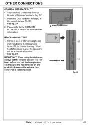
then put the headphones on and gradually increase the volume to a comfortable listening level. 10 14 fig. 29 | HD Ready LCD TV | User Manual p.17 Insert the CAM card (not included) in use a Conditional Access Module (CAM) card to a low level before you put the ...headphones on ; Connect a set the volume control to view a Pay TV. 1. HEADPHONE OUTPUT 1. When headphones are in Common Interface Slot 10 . Please refer to the Headphone Output 14 for more detailed information. IMPORTANT: When using ...
then put the headphones on and gradually increase the volume to a comfortable listening level. 10 14 fig. 29 | HD Ready LCD TV | User Manual p.17 Insert the CAM card (not included) in use a Conditional Access Module (CAM) card to a low level before you put the ...headphones on ; Connect a set the volume control to view a Pay TV. 1. HEADPHONE OUTPUT 1. When headphones are in Common Interface Slot 10 . Please refer to the Headphone Output 14 for more detailed information. IMPORTANT: When using ...
User Manual
Page 20
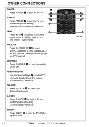
... mode. Select Audio language for ATV channel. INFO 8 • Press INFO 4 to turn the TV off after a preset time. Number Buttons • Use the Number Keys 7 to select TV channels directly. AUDIO I/II • Press the AUDIO I/II 5 to select MONO, STEREO, DUAL...MODE 39 to set the TV to a 6 predefined picture setting. 7 Standard/Vivid/Movie/Eco/Personal. OTHER CONNECTIONS POWER 1 • Press POWER 1 to turn on the TV. 2 3 4 P.MODE 5 • Press P.MODE 3 to set the TV to a predefined sound setting. p.18 | HD Ready LCD TV | User Manual 40 39 ...
... mode. Select Audio language for ATV channel. INFO 8 • Press INFO 4 to turn the TV off after a preset time. Number Buttons • Use the Number Keys 7 to select TV channels directly. AUDIO I/II • Press the AUDIO I/II 5 to select MONO, STEREO, DUAL...MODE 39 to set the TV to a 6 predefined picture setting. 7 Standard/Vivid/Movie/Eco/Personal. OTHER CONNECTIONS POWER 1 • Press POWER 1 to turn on the TV. 2 3 4 P.MODE 5 • Press P.MODE 3 to set the TV to a predefined sound setting. p.18 | HD Ready LCD TV | User Manual 40 39 ...

User Manual
Page 21
... level. A number will disappear. 12 13 Volume Control • Press VOL+ 10 to increase the volume or VOL- 10 to the previous layer. | HD Ready LCD TV | User Manual 40 39 38 37 36 35 fig. 31 34 33 32 31 30 fig. 32 p.19 MENU • Press MENU 11 to confirm...
... level. A number will disappear. 12 13 Volume Control • Press VOL+ 10 to increase the volume or VOL- 10 to the previous layer. | HD Ready LCD TV | User Manual 40 39 38 37 36 35 fig. 31 34 33 32 31 30 fig. 32 p.19 MENU • Press MENU 11 to confirm...
User Manual
Page 22
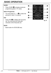
BASIC OPERATION GUIDE 9 Vol • Press GUIDE 34 to display electronic programme guide in the Favourite List. You can save your favourite channels in TV mode. 10 Select Programme 11 • You may press P 33 to select the previous or next TV channel. 12 FAV 13 • Press FAV 32 to display the Favourite list. BACK • Back button for DVD/USB only. 34 33 32 31 30 fig. 33 p.20 | HD Ready LCD TV | User Manual
BASIC OPERATION GUIDE 9 Vol • Press GUIDE 34 to display electronic programme guide in the Favourite List. You can save your favourite channels in TV mode. 10 Select Programme 11 • You may press P 33 to select the previous or next TV channel. 12 FAV 13 • Press FAV 32 to display the Favourite list. BACK • Back button for DVD/USB only. 34 33 32 31 30 fig. 33 p.20 | HD Ready LCD TV | User Manual

User Manual
Page 23
...5KHz Equalizer 10KHz Balance Virtual Surround Personal 3 3 2 4 5 0 Off OK Enter Select EXIT Exit fig. 36 TV Tuner Mode Country Channels Time Shifting Mode Antenna UK On OK Enter Select EXIT Exit fig. 37 | HD Ready LCD TV | User Manual p.21 Features • Enables you to adjust settings of the... TV. See fig. 35. OK Enter Select EXIT Exit fig. 35 TV • Enables you to adjust special functions for the TV channels. Press MENU 4 or 11 to exit...
...5KHz Equalizer 10KHz Balance Virtual Surround Personal 3 3 2 4 5 0 Off OK Enter Select EXIT Exit fig. 36 TV Tuner Mode Country Channels Time Shifting Mode Antenna UK On OK Enter Select EXIT Exit fig. 37 | HD Ready LCD TV | User Manual p.21 Features • Enables you to adjust settings of the... TV. See fig. 35. OK Enter Select EXIT Exit fig. 35 TV • Enables you to adjust special functions for the TV channels. Press MENU 4 or 11 to exit...


