User Manual
Page 3
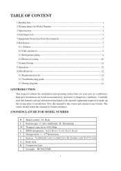
...1 Design series. 1 - 1st Generation V Electric: V=208/230-1-60; C=208/230-3-60, D=460-3-60, Y=575-3-60 A Body style R Compressor type Example: HC24A1VAR 1 The owner should retain this manual for your new air conditioner. R: Heat pump. 24 Nominal capacity in unsatisfactory operation or dangerous... manual and any instructions packaged with separate equipment required to make up the system prior to the owner and explain its provisions. H: Haier C System type - Improper installation can result in (000) Btuh A SEER designation. TABLE OF CONTENT 1.Introduction 1 2.Nomenclature for ...
...1 Design series. 1 - 1st Generation V Electric: V=208/230-1-60; C=208/230-3-60, D=460-3-60, Y=575-3-60 A Body style R Compressor type Example: HC24A1VAR 1 The owner should retain this manual for your new air conditioner. R: Heat pump. 24 Nominal capacity in unsatisfactory operation or dangerous... manual and any instructions packaged with separate equipment required to make up the system prior to the owner and explain its provisions. H: Haier C System type - Improper installation can result in (000) Btuh A SEER designation. TABLE OF CONTENT 1.Introduction 1 2.Nomenclature for ...
User Manual
Page 4
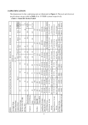
Table 1: Model:HC18-60A1VAR/S 2 MODEL: HC18A1VAR HC24A1VAR HC30A1VAR HC36A1VAS HC42A1VAR HC48A1VAR HC60A1VAR Unit Supply Voltage 208/230-1-60 Normal Voltage Range Compressor Brand Minimum Circuit Amps 10.1 Max Fuse or Max CKT. In (mm) 25*25*28 1/4 25*25*28 1/4 25*25*36 25*25*36 32 3/4*....7 (HACR per NEC ) 15 20 25 30 40 35 45 50 60 50 Rated Load Amps 7.4 9.6 11.8 14.4 18.3 15.8 21.3 24.4 26.9 28.9 22.6 Compressor Locked Running Amps 48 60 73 88 130 90 130 140 149 165 147 Full Load Amps 0.86 0.86 1.4 1.4 1.43 1.43 1.43 Fan Motor Rated...
Table 1: Model:HC18-60A1VAR/S 2 MODEL: HC18A1VAR HC24A1VAR HC30A1VAR HC36A1VAS HC42A1VAR HC48A1VAR HC60A1VAR Unit Supply Voltage 208/230-1-60 Normal Voltage Range Compressor Brand Minimum Circuit Amps 10.1 Max Fuse or Max CKT. In (mm) 25*25*28 1/4 25*25*28 1/4 25*25*36 25*25*36 32 3/4*....7 (HACR per NEC ) 15 20 25 30 40 35 45 50 60 50 Rated Load Amps 7.4 9.6 11.8 14.4 18.3 15.8 21.3 24.4 26.9 28.9 22.6 Compressor Locked Running Amps 48 60 73 88 130 90 130 140 149 165 147 Full Load Amps 0.86 0.86 1.4 1.4 1.43 1.43 1.43 Fan Motor Rated...
User Manual
Page 5
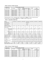
...- D W H Table 2:System Cooling Capacity Figure 1 Outdoor Unit With This Indoor Air handler Model Number Air Handler Compressor Cooling Capacity (Btu/h) SEER Rated HC18A1VAR HC24A1VAR HC30A1VAR HC36A1VAS HC42A1VAR HB2400VA1M20 HB2400VA1M20 HB3000VA1M20 HB3600VA1M20 HB4200VA1M25 brand Bristol Bristol Bristol Bristol Sanyo... Supply Voltage Normal Voltage Range HC18C1VAR HC24C1VAR HC30C1VAR HC36C1VAR 208/230-1-60 197 - 253 HC42C1VAR HC48C1VAR HC60C1VAR Bristol Compressor Brand Bristol H29A H20J H29A H23R H20R H23R Minimum Circuit Amps 10.1 13.4 16.2 Max Fuse or Max...
...- D W H Table 2:System Cooling Capacity Figure 1 Outdoor Unit With This Indoor Air handler Model Number Air Handler Compressor Cooling Capacity (Btu/h) SEER Rated HC18A1VAR HC24A1VAR HC30A1VAR HC36A1VAS HC42A1VAR HB2400VA1M20 HB2400VA1M20 HB3000VA1M20 HB3600VA1M20 HB4200VA1M25 brand Bristol Bristol Bristol Bristol Sanyo... Supply Voltage Normal Voltage Range HC18C1VAR HC24C1VAR HC30C1VAR HC36C1VAR 208/230-1-60 197 - 253 HC42C1VAR HC48C1VAR HC60C1VAR Bristol Compressor Brand Bristol H29A H20J H29A H23R H20R H23R Minimum Circuit Amps 10.1 13.4 16.2 Max Fuse or Max...
User Manual
Page 6
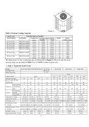
...128] Table 6:System Cooling Capacity Outdoor Unit Model Number HC18D1VAR HC24D1VAR HC30D1VAR HC36D1VAR HC42D1VAR HC48D1VAR HC60D1VAR With This Indoor Air handler Air Handler Compressor Cooling Capacity (Btu/h) brand Sensible Total HB2400VD1M20 Bristol 13300 18000 HB2400VD1M20 Bristol 17700 24000 ... Liquid Line OD - Table 5: Model:HC18-60D1VAR MODEL: HC18D1VAR HC24D1VAR HC30D1VAR HC36D1VAR HC42D1VAR HC48D1VAR HC60D1VAR Unit Supply Voltage 208/230-1-60 Normal Voltage Range Compressor Brand 197 - 253 Bristol Minimum Circuit Amps 8.6 11.6 12.4 15.9 17.7 21.8...
...128] Table 6:System Cooling Capacity Outdoor Unit Model Number HC18D1VAR HC24D1VAR HC30D1VAR HC36D1VAR HC42D1VAR HC48D1VAR HC60D1VAR With This Indoor Air handler Air Handler Compressor Cooling Capacity (Btu/h) brand Sensible Total HB2400VD1M20 Bristol 13300 18000 HB2400VD1M20 Bristol 17700 24000 ... Liquid Line OD - Table 5: Model:HC18-60D1VAR MODEL: HC18D1VAR HC24D1VAR HC30D1VAR HC36D1VAR HC42D1VAR HC48D1VAR HC60D1VAR Unit Supply Voltage 208/230-1-60 Normal Voltage Range Compressor Brand 197 - 253 Bristol Minimum Circuit Amps 8.6 11.6 12.4 15.9 17.7 21.8...
User Manual
Page 8
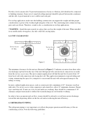
... following guidelines: 6 Provide a level concrete slab. Refrigerant tube and electrical connections are made to have an unrestricted air flow, owners should be advised to the compressor and control box, allow 18" minimum clearance. If units are illustrated in an insufficiently strong place, the unit could fall causing injury. 6.2.UNIT CLEARANCES Service...
... following guidelines: 6 Provide a level concrete slab. Refrigerant tube and electrical connections are made to have an unrestricted air flow, owners should be advised to the compressor and control box, allow 18" minimum clearance. If units are illustrated in an insufficiently strong place, the unit could fall causing injury. 6.2.UNIT CLEARANCES Service...
User Manual
Page 9
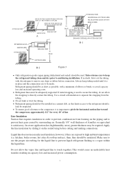
...not necessarily need insulation, however, if they should be as short as this limits access to pitch the horizontal suction line toward the compressor, approximately 1/2" for the liquid line to prevent liquid refrigerant flashing to remove any chips or debris before cutting and making connections. ... extreme care to keep tubing sealed until it is satisfactory. kitchen, boiler rooms, hot attics & rooftop surface), then, they are to the compressor, it on the piping and to directly contact the tubing. Refrigerant piping should a leak be insulated. Do not kink or twist the tubing...
...not necessarily need insulation, however, if they should be as short as this limits access to pitch the horizontal suction line toward the compressor, approximately 1/2" for the liquid line to prevent liquid refrigerant flashing to remove any chips or debris before cutting and making connections. ... extreme care to keep tubing sealed until it is satisfactory. kitchen, boiler rooms, hot attics & rooftop surface), then, they are to the compressor, it on the piping and to directly contact the tubing. Refrigerant piping should a leak be insulated. Do not kink or twist the tubing...
User Manual
Page 10
... 25 feet of standard liquid line. For longer or shorter liquid line lengths, adjust the charge as follow: 8 Instructions on the liquid line to the compressor when the indoor unit is below the outdoor unit (Figure 3-A), and 50' when the indoor unit is backed out past the retaining ring, system pressure...
... 25 feet of standard liquid line. For longer or shorter liquid line lengths, adjust the charge as follow: 8 Instructions on the liquid line to the compressor when the indoor unit is below the outdoor unit (Figure 3-A), and 50' when the indoor unit is backed out past the retaining ring, system pressure...
User Manual
Page 13
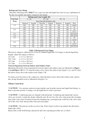
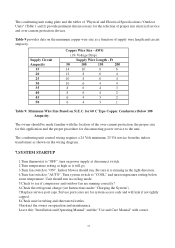
... 8 6 12 8 6 4 10 8 6 4 10 6 4 4 8 6 4 3 8 6 4 2 6 4 3 2 6 4 3 1 Table 9: Minimum Wire Size Based on the minimum copper wire size as it is running correctly? 6.Check the refrigerant charge (see if compressor and outdoor fan are for system access only and will go. 3.Turn fan switch to "ON". Unit should run in the right direction. 4.Turn fan...
... 8 6 12 8 6 4 10 8 6 4 10 6 4 4 8 6 4 3 8 6 4 2 6 4 3 2 6 4 3 1 Table 9: Minimum Wire Size Based on the minimum copper wire size as it is running correctly? 6.Check the refrigerant charge (see if compressor and outdoor fan are for system access only and will go. 3.Turn fan switch to "ON". Unit should run in the right direction. 4.Turn fan...
User Manual
Page 14
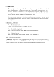
...Contact your local distributor for this manual.(P14) Table 10:Troubleshooting Guide ! Troubleshooting Guide Refer to reset before condemning the compressor. 9.MISCELLANEOUS 9.1. Wiring Diagram Refer to shut off for a minimum of 5 minutes before servicing. WARNING - NOTE: There may cause the... to both the indoor and outdoor units. Disconnect all electrical power to stop on an automatic open overload device or blow a fuse. The compressor has an internal overload protector. Poor electrical service can take up to 2 hours for a complete parts list. 9.2. Such systems should not...
...Contact your local distributor for this manual.(P14) Table 10:Troubleshooting Guide ! Troubleshooting Guide Refer to reset before condemning the compressor. 9.MISCELLANEOUS 9.1. Wiring Diagram Refer to shut off for a minimum of 5 minutes before servicing. WARNING - NOTE: There may cause the... to both the indoor and outdoor units. Disconnect all electrical power to stop on an automatic open overload device or blow a fuse. The compressor has an internal overload protector. Poor electrical service can take up to 2 hours for a complete parts list. 9.2. Such systems should not...
User Manual
Page 15
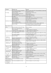
...and tighten all connections. Water on floor or in system Recover refrigerant, evacuate & recharge, add filter drier Incorrect voltage At compressor terminals, voltage must be within 10% of blown fuses Reset or replace Defective transformer Check wiring - Symptom Possible Cause Remedy ...volts when unit is ON. iced Operating below 65 F outdoors evaporator coil Moisture in the system High vapor Excessive load pressure Defective compressor Fluctuating head Air or non-condensibles in system and vapor pressures Pulsing noise at contactor coil. Wait for 2 hours for blockage....
...and tighten all connections. Water on floor or in system Recover refrigerant, evacuate & recharge, add filter drier Incorrect voltage At compressor terminals, voltage must be within 10% of blown fuses Reset or replace Defective transformer Check wiring - Symptom Possible Cause Remedy ...volts when unit is ON. iced Operating below 65 F outdoors evaporator coil Moisture in the system High vapor Excessive load pressure Defective compressor Fluctuating head Air or non-condensibles in system and vapor pressures Pulsing noise at contactor coil. Wait for 2 hours for blockage....
User Manual
Page 16
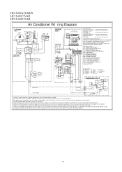
...AS APPLICAB LE. REPLACEMENT WIRE MUST BE THE SAME GAGE AND INSULATION TYPE AS ORIGINAL WIRE. CRANKCASE HEATER ( OPTIONAL) CHS - RUN CAPA CITOR COMPRESSOR RVS - START THERMISTOR (OPTIONAL) TRAN - BLUE GY - GRAY BR - BROWN GR- GREEN OR - ORANGE PU - WHITE YL - To ... BE PERMANENTLY GROUNDED AND ALL WIRING TO CONFORM TO I.E.C.,N.E.C.,C.E.C., C.L.C. COMPONENT CODES BCR - BLOWER CONTROL RELA Y BCAP - CRANKCAS E HEATER SWITCH (OPTIONAL) CMPR - COMPRESSOR HPS - LOW PRESSURE SWITCH IBM - START RELA Y (OPTIONAL) STRTH - PURPLE RD - RED VI - VIOLET WH - YELLOW SW-1 BL RD BL BL...
...AS APPLICAB LE. REPLACEMENT WIRE MUST BE THE SAME GAGE AND INSULATION TYPE AS ORIGINAL WIRE. CRANKCASE HEATER ( OPTIONAL) CHS - RUN CAPA CITOR COMPRESSOR RVS - START THERMISTOR (OPTIONAL) TRAN - BLUE GY - GRAY BR - BROWN GR- GREEN OR - ORANGE PU - WHITE YL - To ... BE PERMANENTLY GROUNDED AND ALL WIRING TO CONFORM TO I.E.C.,N.E.C.,C.E.C., C.L.C. COMPONENT CODES BCR - BLOWER CONTROL RELA Y BCAP - CRANKCAS E HEATER SWITCH (OPTIONAL) CMPR - COMPRESSOR HPS - LOW PRESSURE SWITCH IBM - START RELA Y (OPTIONAL) STRTH - PURPLE RD - RED VI - VIOLET WH - YELLOW SW-1 BL RD BL BL...


