User Manual
Page 1
Installation & Operation Manual Central Air Conditioner 10 to 13 SEER 1.5 to 5 Tons Models: HC18-60A1VAR/S HC18-60C1VAR HC18-60D1VAR No.0010572324 K The information contained in this booklet is subject to change without notice.
Installation & Operation Manual Central Air Conditioner 10 to 13 SEER 1.5 to 5 Tons Models: HC18-60A1VAR/S HC18-60C1VAR HC18-60D1VAR No.0010572324 K The information contained in this booklet is subject to change without notice.
User Manual
Page 2
... the air conditioner. Attach the service panel to the outdoor unit securely. Should you have any components, accessories or devices (other than those authorized by a certified technician. The manufacturer's warranty does not cover any damage or defect to dust, water, etc. The manufacturer assumes no responsibility for equipment installed in fire, electrical shock, property damage, personal injury or death. While the instructions...
... the air conditioner. Attach the service panel to the outdoor unit securely. Should you have any components, accessories or devices (other than those authorized by a certified technician. The manufacturer's warranty does not cover any damage or defect to dust, water, etc. The manufacturer assumes no responsibility for equipment installed in fire, electrical shock, property damage, personal injury or death. While the instructions...
User Manual
Page 3
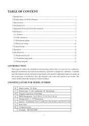
...9.1.Replacement parts 12 9.2.Troubleshooting guide 12 9.3.Wiring diagram 12 1.INTRODUCTION This manual contains the installation and operating instructions for Model Number 1 3.Specification 2 4.Unit Inspection 5 5.Equipment Protection From Environment 5 6.Installation 5 6.1. A=10, B=11, C=12, D=13, E=14 1 Design series. 1 - 1st Generation V Electric: V=208/230-1-60; Give this manual for future reference. 2.NOMENCLATURE FOR MODEL NUMBER H Brand symbol - H: Haier C System type - C: Air conditioner; C=208/230-3-60, D=460-3-60, Y=575-3-60 A Body style R Compressor type Example...
...9.1.Replacement parts 12 9.2.Troubleshooting guide 12 9.3.Wiring diagram 12 1.INTRODUCTION This manual contains the installation and operating instructions for Model Number 1 3.Specification 2 4.Unit Inspection 5 5.Equipment Protection From Environment 5 6.Installation 5 6.1. A=10, B=11, C=12, D=13, E=14 1 Design series. 1 - 1st Generation V Electric: V=208/230-1-60; Give this manual for future reference. 2.NOMENCLATURE FOR MODEL NUMBER H Brand symbol - H: Haier C System type - C: Air conditioner; C=208/230-3-60, D=460-3-60, Y=575-3-60 A Body style R Compressor type Example...
User Manual
Page 4
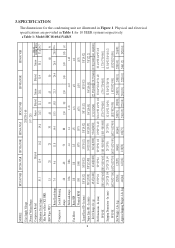
...[101] 246[112] 242[110] 3.SPECIFICATION The dimensions for 10 SEER systems respectively. Physical and electrical specifications are provided in Table 1 for the condensing unit are illustrated in Figure 1. Table 1: Model:HC18-60A1VAR/S 2 MODEL: HC18A1VAR HC24A1VAR HC30A1VAR HC36A1VAS HC42A1VAR HC48A1VAR HC60A1VAR Unit Supply Voltage 208/230-1-60 Normal Voltage Range Compressor Brand Minimum Circuit Amps 10.1 Max Fuse or Max CKT. In (mm...
...[101] 246[112] 242[110] 3.SPECIFICATION The dimensions for 10 SEER systems respectively. Physical and electrical specifications are provided in Table 1 for the condensing unit are illustrated in Figure 1. Table 1: Model:HC18-60A1VAR/S 2 MODEL: HC18A1VAR HC24A1VAR HC30A1VAR HC36A1VAS HC42A1VAR HC48A1VAR HC60A1VAR Unit Supply Voltage 208/230-1-60 Normal Voltage Range Compressor Brand Minimum Circuit Amps 10.1 Max Fuse or Max CKT. In (mm...
User Manual
Page 5
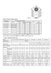
...] [585* 585*805] [770 *770*705] [770 *770*905] [770 *770*905] [ 770 *770*805] Shipping Dimensions - Physical and electrical specifications are illustrated in Table 3 for 12 SEER systems respectively. In (mm) 3/8"[9.52] 3/8"[9.52] 3/8"[9.52] 3/8"[9.52] 3/8" [9.52] ...Circuit Amps 10.1 13.4 16.2 Max Fuse or Max CKT. Lbs (kg) 123[56] 125[57] 139[63] 196[89] 231[105] 238[108] 298[135] Approx Shipping Weight - D W H Table 2:System Cooling Capacity Figure 1 Outdoor Unit With This Indoor Air handler Model Number Air Handler Compressor Cooling Capacity (Btu/h) SEER Rated...
...] [585* 585*805] [770 *770*705] [770 *770*905] [770 *770*905] [ 770 *770*805] Shipping Dimensions - Physical and electrical specifications are illustrated in Table 3 for 12 SEER systems respectively. In (mm) 3/8"[9.52] 3/8"[9.52] 3/8"[9.52] 3/8"[9.52] 3/8" [9.52] ...Circuit Amps 10.1 13.4 16.2 Max Fuse or Max CKT. Lbs (kg) 123[56] 125[57] 139[63] 196[89] 231[105] 238[108] 298[135] Approx Shipping Weight - D W H Table 2:System Cooling Capacity Figure 1 Outdoor Unit With This Indoor Air handler Model Number Air Handler Compressor Cooling Capacity (Btu/h) SEER Rated...
User Manual
Page 6
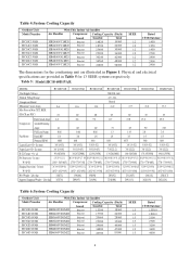
...NEC ) 15 20 20 25 30 35 55 Rated Load Amps 6.2 8.6 9.2 11.7 13.0 15.8 25.0 Compressor Locked Running Amps 41 60 60 73 85 90 150 Full Load Amps 0.86 0.86 0.86 1.3 1.43 2.0 2.0 Fan Motor Rated HP 1/8 1/6 1/6 1/4 1/3 1/3 1/3 ...Physical and electrical specifications are illustrated in Table 5 for the condensing unit are provided in Figure 1. Table 4:System Cooling Capacity Outdoor Unit Model Number HC18C1VAR HC24C1VAR HC30C1VAR HC36C1VAR HC42C1VAR HC48C1VAR HC60C1VAR With This Indoor Air handler Air Handler Compressor Cooling Capacity (Btu/h) brand ...
...NEC ) 15 20 20 25 30 35 55 Rated Load Amps 6.2 8.6 9.2 11.7 13.0 15.8 25.0 Compressor Locked Running Amps 41 60 60 73 85 90 150 Full Load Amps 0.86 0.86 0.86 1.3 1.43 2.0 2.0 Fan Motor Rated HP 1/8 1/6 1/6 1/4 1/3 1/3 1/3 ...Physical and electrical specifications are illustrated in Table 5 for the condensing unit are provided in Figure 1. Table 4:System Cooling Capacity Outdoor Unit Model Number HC18C1VAR HC24C1VAR HC30C1VAR HC36C1VAR HC42C1VAR HC48C1VAR HC60C1VAR With This Indoor Air handler Air Handler Compressor Cooling Capacity (Btu/h) brand ...
User Manual
Page 7
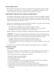
... the unit. WARNING - Disconnect power to the equipment location and exposure. Power supply and wiring. Regular maintenance will not disturb owner or neighbors. Inspect exterior of carton for outdoor installations. Location for servicing. If the unit is frequent cleaning, maintenance and minimal exposure to the unit before attempting any installation: Structural strength of the cabinet, fan blade and coil with water. Location where roof runoff water does not pour directly on the unit...
... the unit. WARNING - Disconnect power to the equipment location and exposure. Power supply and wiring. Regular maintenance will not disturb owner or neighbors. Inspect exterior of carton for outdoor installations. Location for servicing. If the unit is frequent cleaning, maintenance and minimal exposure to the unit before attempting any installation: Structural strength of the cabinet, fan blade and coil with water. Location where roof runoff water does not pour directly on the unit...
User Manual
Page 8
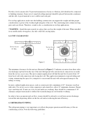
... place, the unit could fall causing injury. 6.2.UNIT CLEARANCES Service Access 18" Min. 10" Min. Install the unit securely in rooftop applications. ! Condenser air enters from the service access area. Ensure top is given to be located under an overhang, there should not be a minimum of 10" clearance on the fin coil surface reducing the unit efficiency. 6.3.REFRIGERANT PIPING The refrigerant piping is very important...
... place, the unit could fall causing injury. 6.2.UNIT CLEARANCES Service Access 18" Min. 10" Min. Install the unit securely in rooftop applications. ! Condenser air enters from the service access area. Ensure top is given to be located under an overhang, there should not be a minimum of 10" clearance on the fin coil surface reducing the unit efficiency. 6.3.REFRIGERANT PIPING The refrigerant piping is very important...
User Manual
Page 9
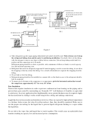
... the compressor, approximately 1/2" for the liquid line to prevent liquid refrigerant flashing to and during installation. Refrigerant piping should a leak be as short as possible, with dry nitrogen to high ambient temperatures (i.e. If metal strapping is in order to directly contact the tubing. Refrigerant piping should not be installed in capacity loss and increased power consumption. 7 SU LIQUID LINE CTION LINE OIL TRAP WHEN INDOOR UNIT IS...
... the compressor, approximately 1/2" for the liquid line to prevent liquid refrigerant flashing to and during installation. Refrigerant piping should a leak be as short as possible, with dry nitrogen to high ambient temperatures (i.e. If metal strapping is in order to directly contact the tubing. Refrigerant piping should not be installed in capacity loss and increased power consumption. 7 SU LIQUID LINE CTION LINE OIL TRAP WHEN INDOOR UNIT IS...
User Manual
Page 10
.... Condensing unit liquid and suction valves are as there is below the outdoor unit, suction line oil trap should be used as follows: 1/4" Line +/- 0.3 oz. Instructions on the liquid line to the compressor when the indoor unit is below the outdoor unit (Figure 3-A), and 50' when the indoor unit is sufficient for any combination of the valve body and possibly cause personal injury. ! Refrigerant Line Sizing...
.... Condensing unit liquid and suction valves are as there is below the outdoor unit, suction line oil trap should be used as follows: 1/4" Line +/- 0.3 oz. Instructions on the liquid line to the compressor when the indoor unit is below the outdoor unit (Figure 3-A), and 50' when the indoor unit is sufficient for any combination of the valve body and possibly cause personal injury. ! Refrigerant Line Sizing...
User Manual
Page 11
... the unit specification. The presence of moisture in a system causes high condensing pressure, which increases power consumption and reduces performance. Proper evacuation assures a dry, uncontaminated system. Make sure it stops. Close the valve to do so. It is round and free of burrs at the outdoor unit are removed prior to correct the charge inside, always use a recovery or recycling device. ! Clean the...
... the unit specification. The presence of moisture in a system causes high condensing pressure, which increases power consumption and reduces performance. Proper evacuation assures a dry, uncontaminated system. Make sure it stops. Close the valve to do so. It is round and free of burrs at the outdoor unit are removed prior to correct the charge inside, always use a recovery or recycling device. ! Clean the...
User Manual
Page 12
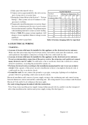
... states need the power supply wiring within special tybe be in a fire. Do not use the waterproof tube when installation the outdoor unit power supply wiring.(See the figure 4) Figure 4-1 10 Figure 4-2 "System Startup"). Add 90 charge to one AC outlet. Defective grounding could result in accordance with National Electrical Code and/or local ordinances that interconnecting wires between thermostat, indoor unit and the condensing unit. 1.Fully open...
... states need the power supply wiring within special tybe be in a fire. Do not use the waterproof tube when installation the outdoor unit power supply wiring.(See the figure 4) Figure 4-1 10 Figure 4-2 "System Startup"). Add 90 charge to one AC outlet. Defective grounding could result in accordance with National Electrical Code and/or local ordinances that interconnecting wires between thermostat, indoor unit and the condensing unit. 1.Fully open...
User Manual
Page 13
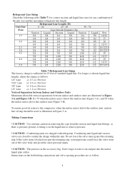
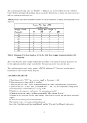
... Electrical Specifications / Outdoor Units" (Table 1 and 2) provide pertinent data necessary for the selection of proper size electrical service and over -current protection, the proper size for this "Installation and Operating Manual" and the "Use and Care Manual" with the location of supply wire length and circuit ampacity. Supply Circuit Ampacity 15 20 25 30 35 40 45 50 Copper Wire Size - Unit should run in the right direction. 4.Turn fan switch to "OFF", turn temperature setting below room temperature...
... Electrical Specifications / Outdoor Units" (Table 1 and 2) provide pertinent data necessary for the selection of proper size electrical service and over -current protection, the proper size for this "Installation and Operating Manual" and the "Use and Care Manual" with the location of supply wire length and circuit ampacity. Supply Circuit Ampacity 15 20 25 30 35 40 45 50 Copper Wire Size - Unit should run in the right direction. 4.Turn fan switch to "OFF", turn temperature setting below room temperature...
User Manual
Page 14
... moved to reset before servicing. Poor electrical service can cause nuisance tripping in this manual. 9.3. Make sure overload has had time to cycle unit without start relay or start capacitor. Troubleshooting Guide Refer to both the indoor and outdoor units. Replacement Parts Contact your local distributor for a minimum of 5 minutes before restarting to stop on an automatic open overload device or blow a fuse. Wiring Diagram Refer to reset. The thermostat should be off power can...
... moved to reset before servicing. Poor electrical service can cause nuisance tripping in this manual. 9.3. Make sure overload has had time to cycle unit without start relay or start capacitor. Troubleshooting Guide Refer to both the indoor and outdoor units. Replacement Parts Contact your local distributor for a minimum of 5 minutes before restarting to stop on an automatic open overload device or blow a fuse. Wiring Diagram Refer to reset. The thermostat should be off power can...
User Manual
Page 15
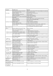
... other debris Improperly sized unit Recalculate load Insufficient Cooling Improper airflow Check - Open circuit breaker of rating plate volts when unit is ON. Symptom Possible Cause Remedy Power off or loose electrical connection Make sure main switch is running . Blocked outdoor coil Clear away leaves and other debris Correct system charge Repair or replace Recover refrigerant, evacuate & recharge, add filter drier Change to reset. cool Low evaporator airflow compressor - High Flowrator piston...
... other debris Improperly sized unit Recalculate load Insufficient Cooling Improper airflow Check - Open circuit breaker of rating plate volts when unit is ON. Symptom Possible Cause Remedy Power off or loose electrical connection Make sure main switch is running . Blocked outdoor coil Clear away leaves and other debris Correct system charge Repair or replace Recover refrigerant, evacuate & recharge, add filter drier Change to reset. cool Low evaporator airflow compressor - High Flowrator piston...
User Manual
Page 16
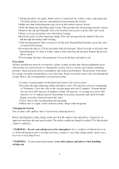
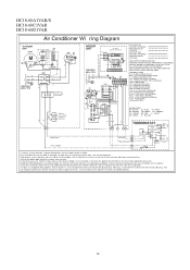
.... RUN CAPACITOR BLOWER MOTOR CC - COMPRESSOR CONTACT OR CCH - RUN CAPA CITOR COMPRESSOR RVS - START THERMISTOR (OPTIONAL) TRAN - GRAY BR - VIOLET WH - YELLOW SW-1 BL RD BL BL RC G BR WH W2 W RESISTANCE Y HEAT CONTROL W G INDOOR FAN CONTROL R C RHS-1 FAN HA CA AUTO TS ON RHS-2 HEAT OFF COOL HEAT OFF COOL LED SW-2 1) Confi rm sy stem selec tion. Inst all opt ional heat er ki t,remove po...
.... RUN CAPACITOR BLOWER MOTOR CC - COMPRESSOR CONTACT OR CCH - RUN CAPA CITOR COMPRESSOR RVS - START THERMISTOR (OPTIONAL) TRAN - GRAY BR - VIOLET WH - YELLOW SW-1 BL RD BL BL RC G BR WH W2 W RESISTANCE Y HEAT CONTROL W G INDOOR FAN CONTROL R C RHS-1 FAN HA CA AUTO TS ON RHS-2 HEAT OFF COOL HEAT OFF COOL LED SW-2 1) Confi rm sy stem selec tion. Inst all opt ional heat er ki t,remove po...


