User Manual
Page 3
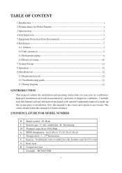
... Generation V Electric: V=208/230-1-60; C: Air conditioner; C=208/230-3-60, D=460-3-60, Y=575-3-60 A Body style R Compressor type Example: HC24A1VAR 1 TABLE OF CONTENT 1.Introduction 1 2.Nomenclature for your new air conditioner. Give this manual to installation. H: Haier C System type - Improper installation can result in (000) Btuh A SEER designation. General 5 6.2.Unit clearances 6 6.3.Refrigerant piping...
... Generation V Electric: V=208/230-1-60; C: Air conditioner; C=208/230-3-60, D=460-3-60, Y=575-3-60 A Body style R Compressor type Example: HC24A1VAR 1 TABLE OF CONTENT 1.Introduction 1 2.Nomenclature for your new air conditioner. Give this manual to installation. H: Haier C System type - Improper installation can result in (000) Btuh A SEER designation. General 5 6.2.Unit clearances 6 6.3.Refrigerant piping...
User Manual
Page 4
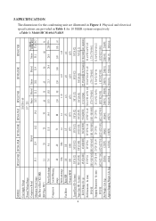
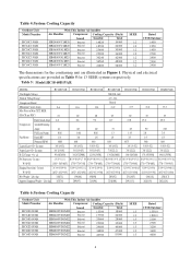
... - Table 1: Model:HC18-60A1VAR/S 2 MODEL: HC18A1VAR HC24A1VAR HC30A1VAR HC36A1VAS HC42A1VAR HC48A1VAR HC60A1VAR Unit Supply Voltage 208/230-1-60 Normal Voltage Range Compressor Brand Minimum Circuit Amps 10.1 Max Fuse or Max CKT. Physical and electrical specifications are illustrated in Table 1 for 10 SEER systems respectively....15 20 25 30 40 35 45 50 60 50 Rated Load Amps 7.4 9.6 11.8 14.4 18.3 15.8 21.3 24.4 26.9 28.9 22.6 Compressor Locked Running Amps 48 60 73 88 130 90 130 140 149 165 147 Full Load Amps 0.86 0.86 1.4 1.4 1.43 1.43 1.43 Fan ...
... - Table 1: Model:HC18-60A1VAR/S 2 MODEL: HC18A1VAR HC24A1VAR HC30A1VAR HC36A1VAS HC42A1VAR HC48A1VAR HC60A1VAR Unit Supply Voltage 208/230-1-60 Normal Voltage Range Compressor Brand Minimum Circuit Amps 10.1 Max Fuse or Max CKT. Physical and electrical specifications are illustrated in Table 1 for 10 SEER systems respectively....15 20 25 30 40 35 45 50 60 50 Rated Load Amps 7.4 9.6 11.8 14.4 18.3 15.8 21.3 24.4 26.9 28.9 22.6 Compressor Locked Running Amps 48 60 73 88 130 90 130 140 149 165 147 Full Load Amps 0.86 0.86 1.4 1.4 1.43 1.43 1.43 Fan ...
User Manual
Page 5
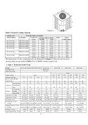
...D W H Table 2:System Cooling Capacity Figure 1 Outdoor Unit With This Indoor Air handler Model Number Air Handler Compressor Cooling Capacity (Btu/h) SEER Rated HC18A1VAR HC24A1VAR HC30A1VAR HC36A1VAS HC42A1VAR HB2400VA1M20 HB2400VA1M20 HB3000VA1M20 HB3600VA1M20 HB4200VA1M25 brand Bristol Bristol Bristol ...MODEL: Unit Supply Voltage Normal Voltage Range HC18C1VAR HC24C1VAR HC30C1VAR HC36C1VAR 208/230-1-60 197 - 253 HC42C1VAR HC48C1VAR HC60C1VAR Bristol Compressor Brand Bristol H29A H20J H29A H23R H20R H23R Minimum Circuit Amps 10.1 13.4 16.2 Max Fuse or Max ...
...D W H Table 2:System Cooling Capacity Figure 1 Outdoor Unit With This Indoor Air handler Model Number Air Handler Compressor Cooling Capacity (Btu/h) SEER Rated HC18A1VAR HC24A1VAR HC30A1VAR HC36A1VAS HC42A1VAR HB2400VA1M20 HB2400VA1M20 HB3000VA1M20 HB3600VA1M20 HB4200VA1M25 brand Bristol Bristol Bristol ...MODEL: Unit Supply Voltage Normal Voltage Range HC18C1VAR HC24C1VAR HC30C1VAR HC36C1VAR 208/230-1-60 197 - 253 HC42C1VAR HC48C1VAR HC60C1VAR Bristol Compressor Brand Bristol H29A H20J H29A H23R H20R H23R Minimum Circuit Amps 10.1 13.4 16.2 Max Fuse or Max ...
User Manual
Page 6
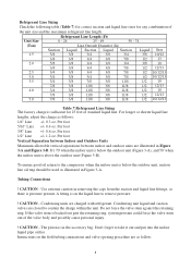
... Unit Model Number HC18D1VAR HC24D1VAR HC30D1VAR HC36D1VAR HC42D1VAR HC48D1VAR HC60D1VAR With This Indoor Air handler Air Handler Compressor Cooling Capacity (Btu/h) brand Sensible Total HB2400VD1M20 Bristol 13300 18000 HB2400VD1M20 Bristol 17700 24000 HB3600VD1M22 Bristol 20669...Table 4:System Cooling Capacity Outdoor Unit Model Number HC18C1VAR HC24C1VAR HC30C1VAR HC36C1VAR HC42C1VAR HC48C1VAR HC60C1VAR With This Indoor Air handler Air Handler Compressor Cooling Capacity (Btu/h) brand Sensible Total HB2400VC1M20 Bristol 14820 19000 HB2400VC1M20 Bristol 18720 ...
... Unit Model Number HC18D1VAR HC24D1VAR HC30D1VAR HC36D1VAR HC42D1VAR HC48D1VAR HC60D1VAR With This Indoor Air handler Air Handler Compressor Cooling Capacity (Btu/h) brand Sensible Total HB2400VD1M20 Bristol 13300 18000 HB2400VD1M20 Bristol 17700 24000 HB3600VD1M22 Bristol 20669...Table 4:System Cooling Capacity Outdoor Unit Model Number HC18C1VAR HC24C1VAR HC30C1VAR HC36C1VAR HC42C1VAR HC48C1VAR HC60C1VAR With This Indoor Air handler Air Handler Compressor Cooling Capacity (Btu/h) brand Sensible Total HB2400VC1M20 Bristol 14820 19000 HB2400VC1M20 Bristol 18720 ...
User Manual
Page 8
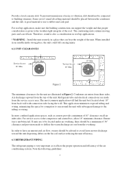
... a place that proper consideration is rubber and cork pad. Service Access 18" Min. 10" Min. 10" 10" Figure 2 The minimum clearances for youngsters to the compressor and control box, allow 18" minimum clearance. For service access to run around the unit with connection side facing the wall. Condenser air enters from...
... a place that proper consideration is rubber and cork pad. Service Access 18" Min. 10" Min. 10" 10" Figure 2 The minimum clearances for youngsters to the compressor and control box, allow 18" minimum clearance. For service access to run around the unit with connection side facing the wall. Condenser air enters from...
User Manual
Page 9
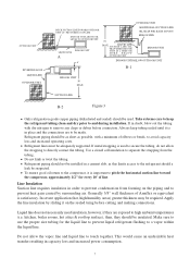
... dry nitrogen to a vapor within the liquid line. Refrigerant piping should be adequately supported. To ensure good oil return to the compressor, it is used . Do not allow the strapping to touch together. If metal strapping is important to pitch the horizontal suction line toward... the compressor, approximately 1/2" for the liquid line to prevent liquid refrigerant flashing to remove any chips or debris before cutting and making connections....
... dry nitrogen to a vapor within the liquid line. Refrigerant piping should be adequately supported. To ensure good oil return to the compressor, it is used . Do not allow the strapping to touch together. If metal strapping is important to pitch the horizontal suction line toward... the compressor, approximately 1/2" for the liquid line to prevent liquid refrigerant flashing to remove any chips or debris before cutting and making connections....
User Manual
Page 10
... ring, system pressure could force the valve stem out of the valve body and possibly cause personal injury. ! Instructions on the liquid line to the compressor when the indoor unit is pressure present.
... ring, system pressure could force the valve stem out of the valve body and possibly cause personal injury. ! Instructions on the liquid line to the compressor when the indoor unit is pressure present.
User Manual
Page 13
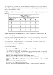
... Wire Size Based on power supply at disconnect switch. 2.Turn temperature setting as high as it is running correctly? 6.Check the refrigerant charge (see if compressor and outdoor fan are for system access only and will go. 3.Turn fan switch to "AUTO". Service port cores are running in cooling mode. 5.Check...
... Wire Size Based on power supply at disconnect switch. 2.Turn temperature setting as high as it is running correctly? 6.Check the refrigerant charge (see if compressor and outdoor fan are for system access only and will go. 3.Turn fan switch to "AUTO". Service port cores are running in cooling mode. 5.Check...
User Manual
Page 14
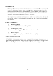
... death. 12 Make sure overload has had time to both the indoor and outdoor units. Disconnect power to reset before condemning the compressor. 9.MISCELLANEOUS 9.1. 8.OPERATION Most single phase units are operated without waiting 5 minutes. The thermostat should be more than one electrical disconnect...Table 10) included in this manual.(P14) Table 10:Troubleshooting Guide ! Failure to shut off for a minimum of pressures. The compressor has an internal overload protector. Under some conditions, it can cause electrical shock resulting in overloads or blow fuses. Wiring Diagram Refer ...
... death. 12 Make sure overload has had time to both the indoor and outdoor units. Disconnect power to reset before condemning the compressor. 9.MISCELLANEOUS 9.1. 8.OPERATION Most single phase units are operated without waiting 5 minutes. The thermostat should be more than one electrical disconnect...Table 10) included in this manual.(P14) Table 10:Troubleshooting Guide ! Failure to shut off for a minimum of pressures. The compressor has an internal overload protector. Under some conditions, it can cause electrical shock resulting in overloads or blow fuses. Wiring Diagram Refer ...
User Manual
Page 15
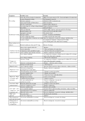
... refrigerant Increase blower speed or reduce restriction - replace air filter Replace defective components Change to correct size piston Replace compressor Replace coil assembly Increase blower speed or reduce restriction - replace air filter Add low ambient kit Recover refrigerant, evacuate...or moisture in system metering device or liquid line Replace Check and tighten all connections. cool Low evaporator airflow compressor - At compressor terminals, voltage must be 400CFM/Ton Incorrect refrigerant charge Charge correctly per instruction. Blocked outdoor coil Clear away...
... refrigerant Increase blower speed or reduce restriction - replace air filter Replace defective components Change to correct size piston Replace compressor Replace coil assembly Increase blower speed or reduce restriction - replace air filter Add low ambient kit Recover refrigerant, evacuate...or moisture in system metering device or liquid line Replace Check and tighten all connections. cool Low evaporator airflow compressor - At compressor terminals, voltage must be 400CFM/Ton Incorrect refrigerant charge Charge correctly per instruction. Blocked outdoor coil Clear away...
User Manual
Page 16
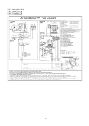
... wire t o cap acitor. 7) Indoor uni t s hipped w ithout optional electr ic heater ki t. REPLACEMENT WIRE MUST BE THE SAME GAGE AND INSULATION TYPE AS ORIGINAL WIRE. COMPRESSOR CONTACT OR CCH - START RELA Y (OPTIONAL) STRTH - WHITE YL - Use only f act ory appr oved accesso ries. 6) Opti onal OFM com ponents m ay connect capac... YL P3 P2 P1 Compress or Prot ect 3 Min. Time Delay BL BL YL LPS 2 HPS YL Opt ional Low & High Pressur e Switches YL CY COMPRESSOR 24VAC COMMON OPTIONAL ELECTRIC HEATER KIT BRK L1 BK FL BK BK FL BK RD RD RD TL L2 RD BK RD RD TL RD...
... wire t o cap acitor. 7) Indoor uni t s hipped w ithout optional electr ic heater ki t. REPLACEMENT WIRE MUST BE THE SAME GAGE AND INSULATION TYPE AS ORIGINAL WIRE. COMPRESSOR CONTACT OR CCH - START RELA Y (OPTIONAL) STRTH - WHITE YL - Use only f act ory appr oved accesso ries. 6) Opti onal OFM com ponents m ay connect capac... YL P3 P2 P1 Compress or Prot ect 3 Min. Time Delay BL BL YL LPS 2 HPS YL Opt ional Low & High Pressur e Switches YL CY COMPRESSOR 24VAC COMMON OPTIONAL ELECTRIC HEATER KIT BRK L1 BK FL BK BK FL BK RD RD RD TL L2 RD BK RD RD TL RD...


