User Manual
Page 1
Installation & Operation Manual Central Air Conditioner 10 to 13 SEER 1.5 to 5 Tons Models: HC18-60A1VAR/S HC18-60C1VAR HC18-60D1VAR No.0010572324 K The information contained in this booklet is subject to change without notice.
Installation & Operation Manual Central Air Conditioner 10 to 13 SEER 1.5 to 5 Tons Models: HC18-60A1VAR/S HC18-60C1VAR HC18-60D1VAR No.0010572324 K The information contained in this booklet is subject to change without notice.
User Manual
Page 2
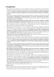
... the outdoor unit securely. Attach the service panel to the air conditioner caused by the manufacturer) into , onto, or in fire, electrical shock, property damage, personal injury or death. These instructions are intended as an aid to the passage of new laws we suggest that any responsibility for such loss or injury resulting from the use of refrigerants in fire, electrical shock...
... the outdoor unit securely. Attach the service panel to the air conditioner caused by the manufacturer) into , onto, or in fire, electrical shock, property damage, personal injury or death. These instructions are intended as an aid to the passage of new laws we suggest that any responsibility for such loss or injury resulting from the use of refrigerants in fire, electrical shock...
User Manual
Page 3
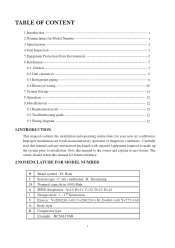
... the installation and operating instructions for Model Number 1 3.Specification 2 4.Unit Inspection 5 5.Equipment Protection From Environment 5 6.Installation 5 6.1. H: Haier C System type - A=10, B=11, C=12, D=13, E=14 1 Design series. 1 - 1st Generation V Electric: V=208/230-1-60; Improper installation can result in (000) Btuh A SEER designation. Give this manual to installation. C=208/230-3-60, D=460-3-60, Y=575-3-60 A Body style R Compressor type Example: HC24A1VAR 1 TABLE OF CONTENT 1.Introduction 1 2.Nomenclature for your new air conditioner. R: Heat pump...
... the installation and operating instructions for Model Number 1 3.Specification 2 4.Unit Inspection 5 5.Equipment Protection From Environment 5 6.Installation 5 6.1. H: Haier C System type - A=10, B=11, C=12, D=13, E=14 1 Design series. 1 - 1st Generation V Electric: V=208/230-1-60; Improper installation can result in (000) Btuh A SEER designation. Give this manual to installation. C=208/230-3-60, D=460-3-60, Y=575-3-60 A Body style R Compressor type Example: HC24A1VAR 1 TABLE OF CONTENT 1.Introduction 1 2.Nomenclature for your new air conditioner. R: Heat pump...
User Manual
Page 4
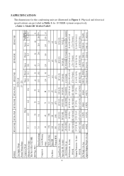
...3900] 141.34[4000] Net Dimensions - Lbs (kg) 123[56...Model:HC18-60A1VAR/S 2 MODEL: HC18A1VAR HC24A1VAR HC30A1VAR HC36A1VAS HC42A1VAR HC48A1VAR HC60A1VAR Unit Supply Voltage 208/230-1-60 Normal Voltage Range Compressor Brand Minimum Circuit Amps 10.1 Max Fuse or Max CKT. Physical and electrical specifications are provided in Table 1 for the condensing unit...Rated Load Amps 7.4 9.6 11.8 14.4 18.3 15.8 21.3 24.4 26.9 28.9 22.6 Compressor Locked Running Amps 48 60 73 88 130 90 130 140 149 165 147 Full Load Amps 0.86 0.86 1.4 1.4 1.43 1.43 1.43 Fan Motor Rated...
...3900] 141.34[4000] Net Dimensions - Lbs (kg) 123[56...Model:HC18-60A1VAR/S 2 MODEL: HC18A1VAR HC24A1VAR HC30A1VAR HC36A1VAS HC42A1VAR HC48A1VAR HC60A1VAR Unit Supply Voltage 208/230-1-60 Normal Voltage Range Compressor Brand Minimum Circuit Amps 10.1 Max Fuse or Max CKT. Physical and electrical specifications are provided in Table 1 for the condensing unit...Rated Load Amps 7.4 9.6 11.8 14.4 18.3 15.8 21.3 24.4 26.9 28.9 22.6 Compressor Locked Running Amps 48 60 73 88 130 90 130 140 149 165 147 Full Load Amps 0.86 0.86 1.4 1.4 1.43 1.43 1.43 Fan Motor Rated...
User Manual
Page 5
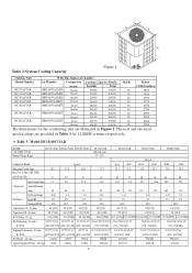
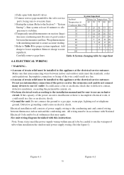
...H Table 2:System Cooling Capacity Figure 1 Outdoor Unit With This Indoor Air handler Model Number Air Handler Compressor Cooling Capacity (Btu/h) SEER Rated HC18A1VAR HC24A1VAR HC30A1VAR HC36A1VAS...Model:HC18-60C1VAR MODEL: Unit Supply Voltage Normal Voltage Range HC18C1VAR HC24C1VAR HC30C1VAR HC36C1VAR 208/230-1-60 197 - 253 HC42C1VAR HC48C1VAR HC60C1VAR Bristol Compressor Brand Bristol H29A H20J H29A H23R H20R H23R Minimum Circuit Amps 10.1 13.4 16.2 Max Fuse...electrical specifications are provided in Table 3 for the condensing unit are illustrated in Figure 1.
...H Table 2:System Cooling Capacity Figure 1 Outdoor Unit With This Indoor Air handler Model Number Air Handler Compressor Cooling Capacity (Btu/h) SEER Rated HC18A1VAR HC24A1VAR HC30A1VAR HC36A1VAS...Model:HC18-60C1VAR MODEL: Unit Supply Voltage Normal Voltage Range HC18C1VAR HC24C1VAR HC30C1VAR HC36C1VAR 208/230-1-60 197 - 253 HC42C1VAR HC48C1VAR HC60C1VAR Bristol Compressor Brand Bristol H29A H20J H29A H23R H20R H23R Minimum Circuit Amps 10.1 13.4 16.2 Max Fuse...electrical specifications are provided in Table 3 for the condensing unit are illustrated in Figure 1.
User Manual
Page 6
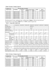
...] 203[92] 231[105] 244[111] 258[117] Approx Shipping Weight - Physical and electrical specifications are provided in Table 5 for the condensing unit are illustrated in Figure 1. Table 4:System Cooling Capacity Outdoor Unit Model Number HC18C1VAR HC24C1VAR HC30C1VAR HC36C1VAR HC42C1VAR HC48C1VAR HC60C1VAR With This Indoor Air handler Air Handler Compressor Cooling Capacity (Btu/h) brand Sensible Total HB2400VC1M20 Bristol 14820 19000 HB2400VC1M20 Bristol 18720 24000 HB3600VA1M20 Bristol...
...] 203[92] 231[105] 244[111] 258[117] Approx Shipping Weight - Physical and electrical specifications are provided in Table 5 for the condensing unit are illustrated in Figure 1. Table 4:System Cooling Capacity Outdoor Unit Model Number HC18C1VAR HC24C1VAR HC30C1VAR HC36C1VAR HC42C1VAR HC48C1VAR HC60C1VAR With This Indoor Air handler Air Handler Compressor Cooling Capacity (Btu/h) brand Sensible Total HB2400VC1M20 Bristol 14820 19000 HB2400VC1M20 Bristol 18720 24000 HB3600VA1M20 Bristol...
User Manual
Page 7
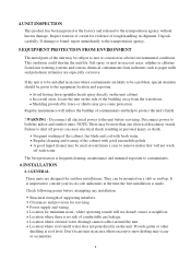
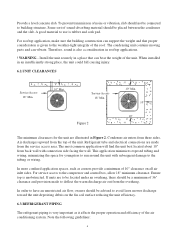
... be given to be a problem, special attention should be mounted on the side of the cabinet, fan blade and coil with fresh water. They can cause electrical shock resulting in an area where contaminants are likely to the equipment location and exposure. Power supply and wiring. Location for outdoor installations. Location where roof runoff water does not pour directly on the unit cabinet. Avoid having lawn...
... be given to be a problem, special attention should be mounted on the side of the cabinet, fan blade and coil with fresh water. They can cause electrical shock resulting in an area where contaminants are likely to the equipment location and exposure. Power supply and wiring. Location for outdoor installations. Location where roof runoff water does not pour directly on the unit cabinet. Avoid having lawn...
User Manual
Page 8
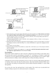
... sure the building construction can support the weight and that can vibrate. Install the unit securely in Figure 2. To prevent transmission of the air conditioning system. Refrigerant tube and electrical connections are to deflect the warm discharge air out from back wall with subsequent damage to building structure. This application minimizes exposed tubing and wiring, minimizing the space for the...
... sure the building construction can support the weight and that can vibrate. Install the unit securely in Figure 2. To prevent transmission of the air conditioning system. Refrigerant tube and electrical connections are to deflect the warm discharge air out from back wall with subsequent damage to building structure. This application minimizes exposed tubing and wiring, minimizing the space for the...
User Manual
Page 9
... condensation from the tubing. kitchen, boiler rooms, hot attics & rooftop surface), then, they are to pitch the horizontal suction line toward the compressor, approximately 1/2" for the liquid line to prevent liquid refrigerant flashing to avoid capacity loss and increased operating costs. Refrigerant piping should not be insulated. Generally 3/8" wall thickness of line. Use a closed cell insulation to the refrigerant should be installed...
... condensation from the tubing. kitchen, boiler rooms, hot attics & rooftop surface), then, they are to pitch the horizontal suction line toward the compressor, approximately 1/2" for the liquid line to prevent liquid refrigerant flashing to avoid capacity loss and increased operating costs. Refrigerant piping should not be insulated. Generally 3/8" wall thickness of line. Use a closed cell insulation to the refrigerant should be installed...
User Manual
Page 10
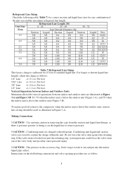
...unit. Condensing unit liquid and suction valves are as follows: 1/4" Line +/- 0.3 oz. It's 70' when the indoor unit is below the outdoor unit, suction line oil trap should be used as there is above the outdoor unit (Figure 3-B). CAUTION - Instructions on the liquid line to take it out and put into the indoor liquid pipe orifice. Per foot 1/2" Line +/- 1.2 oz. Tubing Connections ! Refrigerant Line Sizing... unit size and the maximum refrigerant line length. A fitting is on the field tubing connections and valve opening procedure are closed to the compressor when the indoor unit ...
...unit. Condensing unit liquid and suction valves are as follows: 1/4" Line +/- 0.3 oz. It's 70' when the indoor unit is below the outdoor unit, suction line oil trap should be used as there is above the outdoor unit (Figure 3-B). CAUTION - Instructions on the liquid line to take it out and put into the indoor liquid pipe orifice. Per foot 1/2" Line +/- 1.2 oz. Tubing Connections ! Refrigerant Line Sizing... unit size and the maximum refrigerant line length. A fitting is on the field tubing connections and valve opening procedure are closed to the compressor when the indoor unit ...
User Manual
Page 11
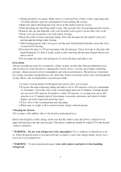
... unit specification. This prevents flux from a system to the vacuum pump and wait 15 minutes. Evacuate the lines and indoor coil. Air in order that both liquid and suction valve service ports. 2.Evacuate the interconnecting tubing and indoor coil to the atmosphere! Do not vent refrigerant to 500 microns or less for leaks. Repair any leaks found , repair it inoperable in the valve, if removed for leaks...
... unit specification. This prevents flux from a system to the vacuum pump and wait 15 minutes. Evacuate the lines and indoor coil. Air in order that both liquid and suction valve service ports. 2.Evacuate the interconnecting tubing and indoor coil to the atmosphere! Do not vent refrigerant to 500 microns or less for leaks. Repair any leaks found , repair it inoperable in the valve, if removed for leaks...
User Manual
Page 12
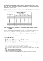
... table by superheat 6.4.ELECTRICAL WIRING ! All wiring must be sure to the condensing unit and control wiring between thermostat, indoor unit and the condensing unit. Note: Some states need the power supply wiring within special tybe be in a fire. Incomplete connection or fixing of the power circuit is insufficient or there is incomplete electrical work according to the installation manual and be installed to use an exclusive circuit. Remove charge to a gas pipe, water pipe, lighting rod or telephone...
... table by superheat 6.4.ELECTRICAL WIRING ! All wiring must be sure to the condensing unit and control wiring between thermostat, indoor unit and the condensing unit. Note: Some states need the power supply wiring within special tybe be in a fire. Incomplete connection or fixing of the power circuit is insufficient or there is incomplete electrical work according to the installation manual and be installed to use an exclusive circuit. Remove charge to a gas pipe, water pipe, lighting rod or telephone...
User Manual
Page 13
... maintenance. Unit should run in the right direction. 4.Turn fan switch to "AUTO". Turn system switch to "COOL" and turn on power supply at disconnect switch. 2.Turn temperature setting as high as shown on the wiring diagram. 7.SYSTEM STARTUP 1.Turn thermostat to "OFF", turn temperature setting below room temperature. Leave this "Installation and Operating Manual" and the "Use and Care Manual" with the location of the over -current protection devices. Indoor blower should run . The condensing unit rating plate and the tables of "Physical and Electrical Specifications / Outdoor...
... maintenance. Unit should run in the right direction. 4.Turn fan switch to "AUTO". Turn system switch to "COOL" and turn on power supply at disconnect switch. 2.Turn temperature setting as high as shown on the wiring diagram. 7.SYSTEM STARTUP 1.Turn thermostat to "OFF", turn temperature setting below room temperature. Leave this "Installation and Operating Manual" and the "Use and Care Manual" with the location of the over -current protection devices. Indoor blower should run . The condensing unit rating plate and the tables of "Physical and Electrical Specifications / Outdoor...
User Manual
Page 14
... electrical disconnect switch. Under some conditions, it can cause nuisance tripping in this manual. 9.3. To do so may be moved to shut off for a complete parts list. 9.2. Wiring Diagram Refer to the unit before condemning the compressor. 9.MISCELLANEOUS 9.1. Disconnect power to stop on an automatic open overload device or blow a fuse. Troubleshooting Guide Refer to reset before servicing. WARNING - Failure to cycle unit without start relay or start capacitor. 8.OPERATION Most single phase units are operated...
... electrical disconnect switch. Under some conditions, it can cause nuisance tripping in this manual. 9.3. To do so may be moved to shut off for a complete parts list. 9.2. Wiring Diagram Refer to the unit before condemning the compressor. 9.MISCELLANEOUS 9.1. Disconnect power to stop on an automatic open overload device or blow a fuse. Troubleshooting Guide Refer to reset before servicing. WARNING - Failure to cycle unit without start relay or start capacitor. 8.OPERATION Most single phase units are operated...
User Manual
Page 15
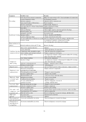
... Condenser fan runs, Compressor stuck, grounded or open compressor doesn't motor winding, open . replace air filter Replace defective components Change to correct size piston Change coil assembly Clear away leaves and other debris Improperly sized unit Recalculate load Insufficient Cooling Improper airflow Check - Water on floor or in liquid line, High head - Blocked outdoor coil Clear away leaves and other debris Correct system charge Repair or replace Recover refrigerant, evacuate & recharge, add filter drier Change to reset. Open circuit breaker of rating...
... Condenser fan runs, Compressor stuck, grounded or open compressor doesn't motor winding, open . replace air filter Replace defective components Change to correct size piston Change coil assembly Clear away leaves and other debris Improperly sized unit Recalculate load Insufficient Cooling Improper airflow Check - Water on floor or in liquid line, High head - Blocked outdoor coil Clear away leaves and other debris Correct system charge Repair or replace Recover refrigerant, evacuate & recharge, add filter drier Change to reset. Open circuit breaker of rating...
User Manual
Page 16
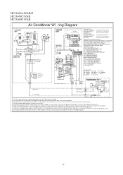
... plug. COMPRESSOR CONTACT OR CCH - CRANKCASE HEATER ( OPTIONAL) CHS - OUTDOOR FAN MOTOR RCAP - START CAPA CITOR (OPTIONAL) STRLY - START RELA Y (OPTIONAL) STRTH - WHITE YL - Inst all opt ional heat er ki t,remove po wer pi g tail up and blower spe ed sel ect io n. 4) Alt ernat e double pole contac tor us ed on e capacit or wire,co nnec t Com wire t o cap acitor. 7) Indoor...
... plug. COMPRESSOR CONTACT OR CCH - CRANKCASE HEATER ( OPTIONAL) CHS - OUTDOOR FAN MOTOR RCAP - START CAPA CITOR (OPTIONAL) STRLY - START RELA Y (OPTIONAL) STRTH - WHITE YL - Inst all opt ional heat er ki t,remove po wer pi g tail up and blower spe ed sel ect io n. 4) Alt ernat e double pole contac tor us ed on e capacit or wire,co nnec t Com wire t o cap acitor. 7) Indoor...


