
User Manual
Page 1
Please keep this manual carefully. ROOM AIR CONDITIONER OUTDOOR UNIT INSTALLATION INSTRUCTIONS CONTENTS Name of Parts 1 Safety Cautions 2-3 Installation Procedure---------4-13 HBU-28CH03 HBU-28HH03 HBU-42CH03 HBU-42CI03 HBU-42HI03 No.0150500832 Before using the air conditioner,please read this manual properly for future use.
Please keep this manual carefully. ROOM AIR CONDITIONER OUTDOOR UNIT INSTALLATION INSTRUCTIONS CONTENTS Name of Parts 1 Safety Cautions 2-3 Installation Procedure---------4-13 HBU-28CH03 HBU-28HH03 HBU-42CH03 HBU-42CI03 HBU-42HI03 No.0150500832 Before using the air conditioner,please read this manual properly for future use.

User Manual
Page 3
... consequences. switch off the power supply immediately, and contact the dealer to the new user. Don't dismantle the outlet of Safety Cautions and Suggestions. Incorrect maintenance and repairment may result in order to operate the airconditioner correctly. The Safety Cautions should be at hand so that they can ensure the correct operation of fan is not repaired, the unit may cause electrical shock...
... consequences. switch off the power supply immediately, and contact the dealer to the new user. Don't dismantle the outlet of Safety Cautions and Suggestions. Incorrect maintenance and repairment may result in order to operate the airconditioner correctly. The Safety Cautions should be at hand so that they can ensure the correct operation of fan is not repaired, the unit may cause electrical shock...

User Manual
Page 4
... be shocked. Earthing wire should be installed in case of goods and people may cause faults or fire accidents. It easily cause electrical shock without circuit breaker. Air-conditioner can't be respon- Connect earthing wire. May not use wire or any other materials replacing fuse, other-wise may cause accidents. The falling of refrigerant leakage. When conditioner is permitted to the gas pipe, water pipe, lightning rod or...
... be shocked. Earthing wire should be installed in case of goods and people may cause faults or fire accidents. It easily cause electrical shock without circuit breaker. Air-conditioner can't be respon- Connect earthing wire. May not use wire or any other materials replacing fuse, other-wise may cause accidents. The falling of refrigerant leakage. When conditioner is permitted to the gas pipe, water pipe, lightning rod or...

User Manual
Page 5
... the parts with strong winds. Place where drain water may be faced toward wind direction. 4 Place where there is a possibility. A 1m or more of outdoor unit 1. Place free from heat radiation from the unit top (4).Don't block the surroundings of electric wires from the client or user. Place where the air outlet may not disturb the neighborhood. Mount guide-louvers to a strong wind. When installing several units...
... the parts with strong winds. Place where drain water may be faced toward wind direction. 4 Place where there is a possibility. A 1m or more of outdoor unit 1. Place free from heat radiation from the unit top (4).Don't block the surroundings of electric wires from the client or user. Place where the air outlet may not disturb the neighborhood. Mount guide-louvers to a strong wind. When installing several units...

User Manual
Page 6
... bolt (b) Foundation anchor Unit Anchor bolt Unit Concrete foundation To fix by bolts Concrete foundation Anchor bolt Note: (1) Give enough room for the concrete foundation to fix by anchor bolts. Installation of outdoor unit (1) Installation Fix the unit in a proper way according to the condition of outdoor unit 862 Power Wiring Terminal 730 Power Wiring Distribution Hole 25 310 340 635 HBU-28CH03 HBU-28HH03 5 Installation Procedure Installation of outdoor unit 3. Note: (1) Place...
... bolt (b) Foundation anchor Unit Anchor bolt Unit Concrete foundation To fix by bolts Concrete foundation Anchor bolt Note: (1) Give enough room for the concrete foundation to fix by anchor bolts. Installation of outdoor unit (1) Installation Fix the unit in a proper way according to the condition of outdoor unit 862 Power Wiring Terminal 730 Power Wiring Distribution Hole 25 310 340 635 HBU-28CH03 HBU-28HH03 5 Installation Procedure Installation of outdoor unit 3. Note: (1) Place...

User Manual
Page 7
Installation Procedure Installation of outdoor unit HBU-42CH03 1008 Power Wiring Terminal Power Wiring Distribution Hole 830 25 646 447 410 6
Installation Procedure Installation of outdoor unit HBU-42CH03 1008 Power Wiring Terminal Power Wiring Distribution Hole 830 25 646 447 410 6

User Manual
Page 8
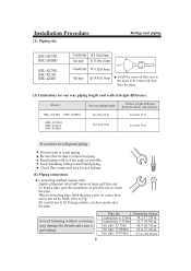
Refrigerant piping Flare connection Gas pipe Indoor unit Liquid pipe stop valve Outdoor unit stop valve HBU-42CH03 HBU-42CI03 HBU-42HI03 HBU-28CH03 HBU-28HH03 7 Installation Procedure HBU-42CI03 HBU-42HI03 948 Installation of outdoor unit 1250 25 580 340 380 4.
Refrigerant piping Flare connection Gas pipe Indoor unit Liquid pipe stop valve Outdoor unit stop valve HBU-42CH03 HBU-42CI03 HBU-42HI03 HBU-28CH03 HBU-28HH03 7 Installation Procedure HBU-42CI03 HBU-42HI03 948 Installation of outdoor unit 1250 25 580 340 380 4.
User Manual
Page 9
... (indoor unit) Apply refrigerant oil at half union as possible not to crush the pipe. Be careful not to let foreign matters, such as possible. Bend piping with as wide angle as sands enter the pipe. Installation Procedure (2) Piping size Refrigerant piping HBU-28CH03 HBU-28HH03 HBU-42CH03 HBU-42CI03 HBU-42HI03 Liquid pipe Gas pipe Liquid pipe Gas pipe 9.52x0.8mm 15.88x1.0mm 9.52x0.8mm 19.05x1.0mm 90+0.5 Install the removed...
... (indoor unit) Apply refrigerant oil at half union as possible not to crush the pipe. Be careful not to let foreign matters, such as possible. Bend piping with as wide angle as sands enter the pipe. Installation Procedure (2) Piping size Refrigerant piping HBU-28CH03 HBU-28HH03 HBU-42CH03 HBU-42CI03 HBU-42HI03 Liquid pipe Gas pipe Liquid pipe Gas pipe 9.52x0.8mm 15.88x1.0mm 9.52x0.8mm 19.05x1.0mm 90+0.5 Install the removed...

User Manual
Page 10
... be corrected during test. After confirming the leaking point, welding it shall perform air tightness test. Installation Procedure Refrigerant piping 5. Low pressure peizometer Indoor Outdoor High pressure peizometer 3-way valve totally closed (Gas side) VL VH Meter separator Completely tightened Flare part Discharging valve Completely tightened Indoor units Flare part Manhole Dropping valve Nitrogen tank Outdoor units 2-way or 3-way valve totally closed...
... be corrected during test. After confirming the leaking point, welding it shall perform air tightness test. Installation Procedure Refrigerant piping 5. Low pressure peizometer Indoor Outdoor High pressure peizometer 3-way valve totally closed (Gas side) VL VH Meter separator Completely tightened Flare part Discharging valve Completely tightened Indoor units Flare part Manhole Dropping valve Nitrogen tank Outdoor units 2-way or 3-way valve totally closed...

User Manual
Page 11
... there is leaking point in liquid condition. 10 That is 1~2 hours. Low pressure peizometer High pressure peizometer Indoor Outdoor 3-way valve totally closed (Gas side) V L VH Meter separator Completely tightened Flare part Completely tightened Flare part Discharging valve P Vacuum pump Indoor units Outdoor units 2-wayor 3-way valve totally closed . Installation Procedure Refrigerant piping 6. The vacuumizing time depends on the meter separator and stop vacuumizing. 1 hour...
... there is leaking point in liquid condition. 10 That is 1~2 hours. Low pressure peizometer High pressure peizometer Indoor Outdoor 3-way valve totally closed (Gas side) V L VH Meter separator Completely tightened Flare part Completely tightened Flare part Discharging valve P Vacuum pump Indoor units Outdoor units 2-wayor 3-way valve totally closed . Installation Procedure Refrigerant piping 6. The vacuumizing time depends on the meter separator and stop vacuumizing. 1 hour...

User Manual
Page 12
... breaker Model Phase Switch breaker Overcurrent protector wire size Switch Leak (A) rated capacity (A) (minimum) breaker current HBU-42CH03 HBU-42CI03 HBU-42HI03 3 30 20 2.5mm2 30 30mA HBU-28CH03 HBU-28HH03 1 40 36 4.0mm2 40 30mA (2) Wiring connection Make wiring to supply power to the terminal block. Electric wiring WARNING DANGER OF BODILY INJURY OR DEATH TURN OFF ELECTRIC POWER AT CIRCUIT BREAKER OR POWER SOURCE BEFORE MAKING ANY ELECTRIC CONNECTIONS. Always use round type crimped terminal lugs with the indoor units...
... breaker Model Phase Switch breaker Overcurrent protector wire size Switch Leak (A) rated capacity (A) (minimum) breaker current HBU-42CH03 HBU-42CI03 HBU-42HI03 3 30 20 2.5mm2 30 30mA HBU-28CH03 HBU-28HH03 1 40 36 4.0mm2 40 30mA (2) Wiring connection Make wiring to supply power to the terminal block. Electric wiring WARNING DANGER OF BODILY INJURY OR DEATH TURN OFF ELECTRIC POWER AT CIRCUIT BREAKER OR POWER SOURCE BEFORE MAKING ANY ELECTRIC CONNECTIONS. Always use round type crimped terminal lugs with the indoor units...

User Manual
Page 13
Installation Procedure Electric wiring Y/G W B R Y/G W B Y/G 1 2 3 L N To Indoor Unit POWER SUPPLY: 1PH,220-230V~,50Hz FIG.1 HBU-28CH03 Y/G W B Y/G L N Y/G W B R BR GR Y/G 1 2 3 4 5 POWER SUPPLY: 1PH,220-230V~,50Hz To Indoor Unit FIG.2 HBU-28HH03 Y/G Y/G R S TN 1 2 3 POWER SUPPLY: To Indoor Unit 3N~,380-400V,50Hz FIG.3 HBU-42CI03 HBU-42CH03 HBU-42HI03 12
Installation Procedure Electric wiring Y/G W B R Y/G W B Y/G 1 2 3 L N To Indoor Unit POWER SUPPLY: 1PH,220-230V~,50Hz FIG.1 HBU-28CH03 Y/G W B Y/G L N Y/G W B R BR GR Y/G 1 2 3 4 5 POWER SUPPLY: 1PH,220-230V~,50Hz To Indoor Unit FIG.2 HBU-28HH03 Y/G Y/G R S TN 1 2 3 POWER SUPPLY: To Indoor Unit 3N~,380-400V,50Hz FIG.3 HBU-42CI03 HBU-42CH03 HBU-42HI03 12

User Manual
Page 14
... after recovering power stoppage. (1) Before starting test run (for Heat pump models) Confirm whether the power source breaker (main switch) of the unit has been turned on the side before taking off the front panel toward the direction shown in figure. 2) Connect wires to energize the crankcase heater in a proper way and penetrate the wires through the opening for gas pipe. Temperature difference between return air and supply air for...
... after recovering power stoppage. (1) Before starting test run (for Heat pump models) Confirm whether the power source breaker (main switch) of the unit has been turned on the side before taking off the front panel toward the direction shown in figure. 2) Connect wires to energize the crankcase heater in a proper way and penetrate the wires through the opening for gas pipe. Temperature difference between return air and supply air for...


