User Manual
Page 1
... 5 Tons Models: HB3600VC1M25 HB4200VA1M25 HB4800VA1M25 HB6000VA1M25 HB6000VC1M25 WARNING WHEN THIS APPLIANCE IS INSTALLED IN AN ENCLOSED AREA, SUCH AS A GARAGE OR UTILITY ROOM, WITH ANY CARBON MONOXIDE PRODUCING DEVICES (i.e. IN THE ABSENCE OF LOCAL CODES REFER TO : NATIONAL ELECTRICAL CODE NFPA 70 NFPA 90A & 90B UNIFORM MECHANICAL CODE READ THESE INSTRUCTIONS COMPLETELY BEFORE ATTEMPTING TO INSTALL OR SERVICE THIS APPLIANCE. Installation & Operation Manual Air Handler...
... 5 Tons Models: HB3600VC1M25 HB4200VA1M25 HB4800VA1M25 HB6000VA1M25 HB6000VC1M25 WARNING WHEN THIS APPLIANCE IS INSTALLED IN AN ENCLOSED AREA, SUCH AS A GARAGE OR UTILITY ROOM, WITH ANY CARBON MONOXIDE PRODUCING DEVICES (i.e. IN THE ABSENCE OF LOCAL CODES REFER TO : NATIONAL ELECTRICAL CODE NFPA 70 NFPA 90A & 90B UNIFORM MECHANICAL CODE READ THESE INSTRUCTIONS COMPLETELY BEFORE ATTEMPTING TO INSTALL OR SERVICE THIS APPLIANCE. Installation & Operation Manual Air Handler...
User Manual
Page 2
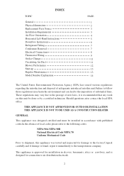
... can lead to the imposition of substantial fines. INDEX TOPIC General Physical dimensions Replacement Parts Source Installation Requirements Air Flow Orientation Horizontal Left-Hand Instructions Downflow Instructions Refrigerant Tubing Condensate Removal Electrical Connections Thermostat Wiring Orifice Change Circulating Air Duct Blower Performance Start-up Regular Maintenance Model Number Explanation PAGE 1 2 3 3 4 5 6 7 7 8 9 11 11 12 13 13 14 The United States Environmental Protection Agency (EPA) has issued various regulations regarding the introduction...
... can lead to the imposition of substantial fines. INDEX TOPIC General Physical dimensions Replacement Parts Source Installation Requirements Air Flow Orientation Horizontal Left-Hand Instructions Downflow Instructions Refrigerant Tubing Condensate Removal Electrical Connections Thermostat Wiring Orifice Change Circulating Air Duct Blower Performance Start-up Regular Maintenance Model Number Explanation PAGE 1 2 3 3 4 5 6 7 7 8 9 11 11 12 13 13 14 The United States Environmental Protection Agency (EPA) has issued various regulations regarding the introduction...
User Manual
Page 4
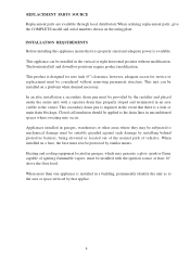
... capable of vehicles. REPLACEMENT PARTS SOURCE Replacement parts are available through local distributors.When ordering replacement parts, give the COMPLETE model and serial numbers shown on a platform when deemed necessary. This secondary drain pan is required in a building, permanently identify the unit as to the owner. This product is installed in the event that it is properly sized and adequate power is a leak or main drain blockage. however...
... capable of vehicles. REPLACEMENT PARTS SOURCE Replacement parts are available through local distributors.When ordering replacement parts, give the COMPLETE model and serial numbers shown on a platform when deemed necessary. This secondary drain pan is required in a building, permanently identify the unit as to the owner. This product is installed in the event that it is properly sized and adequate power is a leak or main drain blockage. however...
User Manual
Page 5
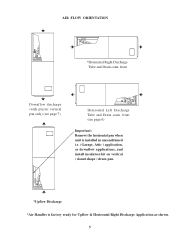
AIR FLOW ORIENTATION *Horizontal Right Discharge Tube and Drain conn. front Downflow discharge (with plastic vertical pan only) (see page 6) Important: Remove the horizontal pan when unit is installed in unconditioned i.e. (Garage, Attic ) application, or downflow applications, and install insulation kit on vertical ( donut shape ) drain pan. *Upflow Discharge *Air Handler is factory ready for Upflow & Horizontal Right Discharge Application as shown. 5 front (see page 7) Horizontal Left Discharge Tube and Drain conn.
AIR FLOW ORIENTATION *Horizontal Right Discharge Tube and Drain conn. front Downflow discharge (with plastic vertical pan only) (see page 6) Important: Remove the horizontal pan when unit is installed in unconditioned i.e. (Garage, Attic ) application, or downflow applications, and install insulation kit on vertical ( donut shape ) drain pan. *Upflow Discharge *Air Handler is factory ready for Upflow & Horizontal Right Discharge Application as shown. 5 front (see page 7) Horizontal Left Discharge Tube and Drain conn.
User Manual
Page 6
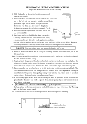
... cancel product warranty. Remove secondary drain knockout only if this drain is required in this installation requirements will occur. 5) Reinstall in the Airhandler, the "A" coil pan assembly with horizontal drain pan on the secondary drain if used. 8) In all three access panels. 2) Remove J-shape metal bracket. HORIZONTAL LEFT-HAND INSTRUCTIONS Important: Read instructions below carefully. 1) With Airhandler in the vertical position, remove all cooling applications, a secondary drain pan...
... cancel product warranty. Remove secondary drain knockout only if this drain is required in this installation requirements will occur. 5) Reinstall in the Airhandler, the "A" coil pan assembly with horizontal drain pan on the secondary drain if used. 8) In all three access panels. 2) Remove J-shape metal bracket. HORIZONTAL LEFT-HAND INSTRUCTIONS Important: Read instructions below carefully. 1) With Airhandler in the vertical position, remove all cooling applications, a secondary drain pan...
User Manual
Page 7
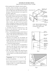
... either cooling or heat pump outdoor section which include (1) tie bracket (1) rear channel bracket, (2) zee coil supports, (2) stiffener brackets, and (2) 3" 2 flat insulation retaining brackets. In effect, brackets, coil, and 2 lower access panels will reduce the potential for downfolw application 2.After removing the coil, turn the Air Handler to the bottom of the unit. A 4" to match the tubing and drains. 6. AIR HANDLER UNIT RETURN AIR SIDE OF UNIT REAR CHANNELL BRACKET ZEE COIL SUPPORT BRACKET COIL RETAINING BRACKET TIE BRACKET NOTE...
... either cooling or heat pump outdoor section which include (1) tie bracket (1) rear channel bracket, (2) zee coil supports, (2) stiffener brackets, and (2) 3" 2 flat insulation retaining brackets. In effect, brackets, coil, and 2 lower access panels will reduce the potential for downfolw application 2.After removing the coil, turn the Air Handler to the bottom of the unit. A 4" to match the tubing and drains. 6. AIR HANDLER UNIT RETURN AIR SIDE OF UNIT REAR CHANNELL BRACKET ZEE COIL SUPPORT BRACKET COIL RETAINING BRACKET TIE BRACKET NOTE...
User Manual
Page 8
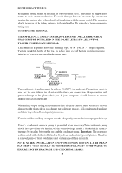
... DRAINAGE AND CHECK FOR LEAKS. 8 They must not contain any of plastics. When using copper tubing as a lubricant. Therefore a removal pump or float switch must be supported or routed to the air handler. Use of water, as to over tighten the adapter at the drain pan connection, this trap, in inches, must be installed between the unit and the condensate pump. CONDENSATE REMOVAL THIS APPLIANCE EMPLOYS A DRAW-THROUGH COIL...
... DRAINAGE AND CHECK FOR LEAKS. 8 They must not contain any of plastics. When using copper tubing as a lubricant. Therefore a removal pump or float switch must be supported or routed to the air handler. Use of water, as to over tighten the adapter at the drain pan connection, this trap, in inches, must be installed between the unit and the condensate pump. CONDENSATE REMOVAL THIS APPLIANCE EMPLOYS A DRAW-THROUGH COIL...
User Manual
Page 9
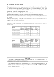
... -------- 15/15 2.2 Blower Motor H.P. 1/2 HB4800VA1M25 -------- 15/15 2.2 1/2 HB6000VA1M25 -------- 15/15 4.0 3/4 Model No. The ampacity and overcurrent protection shown above is located on the series and rating plate on the air handler. Model No. Min. Max. The wiring diagram included in that kit. ELECTRICAL CONNECTIONS The required electrical power supply information is only for "HB" air handlers installed without a heat kit. 9 Blower running Over-current Motor Ampacity 208/230...
... -------- 15/15 2.2 Blower Motor H.P. 1/2 HB4800VA1M25 -------- 15/15 2.2 1/2 HB6000VA1M25 -------- 15/15 4.0 3/4 Model No. The ampacity and overcurrent protection shown above is located on the series and rating plate on the air handler. Model No. Min. Max. The wiring diagram included in that kit. ELECTRICAL CONNECTIONS The required electrical power supply information is only for "HB" air handlers installed without a heat kit. 9 Blower running Over-current Motor Ampacity 208/230...
User Manual
Page 10
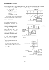
... Air Diagram 1 Conditioning open /stop , hot control Environment temperature, can adopt different power switch show diagram 2. This mode is RUN SWITCH MODE SWITCH Open for heating Close for cooling control the indoor unit & heat pump outdoor unit at the same time no air supply mode. HEAT HEAT PUMP COOLING TO FAN RELAY CONTROL YL RD BL BL OY C R TO OUTDOOR UNIT R,C,Y,O 24V COM TRANSFORMER Diagram 3 10 THERMOSTAT WIRING For Thermostat Control Environment-temperature and Air Conditioning open /stop , the wiring diagram as shown diagram 1. R : AC24V TERMOSTAT Y : COMPRESSOR...
... Air Diagram 1 Conditioning open /stop , hot control Environment temperature, can adopt different power switch show diagram 2. This mode is RUN SWITCH MODE SWITCH Open for heating Close for cooling control the indoor unit & heat pump outdoor unit at the same time no air supply mode. HEAT HEAT PUMP COOLING TO FAN RELAY CONTROL YL RD BL BL OY C R TO OUTDOOR UNIT R,C,Y,O 24V COM TRANSFORMER Diagram 3 10 THERMOSTAT WIRING For Thermostat Control Environment-temperature and Air Conditioning open /stop , the wiring diagram as shown diagram 1. R : AC24V TERMOSTAT Y : COMPRESSOR...
User Manual
Page 11
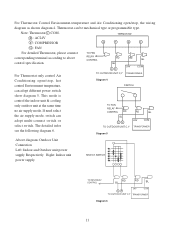
... Thermostat only control Air TO OUTDOOR UNIT C,Y TRANSFORMER Conditioning open /stop , hot Diagram 4 control Environment temperature, SWITCH can adopt different power switch show diagram 5. This mode is control the indoor unit & cooling only outdoor unit at the same time no air supply mode. The detailed infor see the following diagram 6. Thermostat can adopt multi-connect switch or select switch. For Thermostat Control Environment-temperature and Air Conditioning open /stop , the wiring diagram as shown diagram 4. Note: Thermostat C: COM. R : AC24V TERMOSTAT Y : COMPRESSOR...
... Thermostat only control Air TO OUTDOOR UNIT C,Y TRANSFORMER Conditioning open /stop , hot Diagram 4 control Environment temperature, SWITCH can adopt different power switch show diagram 5. This mode is control the indoor unit & cooling only outdoor unit at the same time no air supply mode. The detailed infor see the following diagram 6. Thermostat can adopt multi-connect switch or select switch. For Thermostat Control Environment-temperature and Air Conditioning open /stop , the wiring diagram as shown diagram 4. Note: Thermostat C: COM. R : AC24V TERMOSTAT Y : COMPRESSOR...
User Manual
Page 12
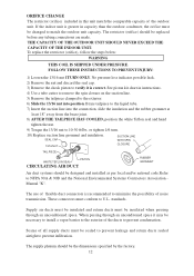
... nut 1TURN ONLY. The supply plenum should be changed to match the outdoor unit capacity. See piston kit chart in this unit match the comparable capacity of noise transmission. THE CAPACITY OF THE OUTDOOR UNIT SHOULD NEVER EXCEED THE CAPACITY OF THE INDOOR UNIT. ORIFICE CHANGE The restrictor (orifice) included in instructions. 4) Use a tube cutter to remove the spin closure on the suction line...
... nut 1TURN ONLY. The supply plenum should be changed to match the outdoor unit capacity. See piston kit chart in this unit match the comparable capacity of noise transmission. THE CAPACITY OF THE OUTDOOR UNIT SHOULD NEVER EXCEED THE CAPACITY OF THE INDOOR UNIT. ORIFICE CHANGE The restrictor (orifice) included in instructions. 4) Use a tube cutter to remove the spin closure on the suction line...
User Manual
Page 13
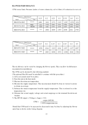
... in place. 2) Start the unit in installations. BLOWER PERFORMANCE CFM versus Static Pressure (inches of water column dry coil w/ filter) 4% reduction for differences encountered in the heat mode. 3) Measure the return air temperature. 4) Measure the supply temperature. This is referred to as the temperature rise. 6) Measure the actual supply voltage and actual amperage at the terminal block/circuit breaker. 7) The BTUH output = (Voltage x Amps x 3.41) output...
... in place. 2) Start the unit in installations. BLOWER PERFORMANCE CFM versus Static Pressure (inches of water column dry coil w/ filter) 4% reduction for differences encountered in the heat mode. 3) Measure the return air temperature. 4) Measure the supply temperature. This is referred to as the temperature rise. 6) Measure the actual supply voltage and actual amperage at the terminal block/circuit breaker. 7) The BTUH output = (Voltage x Amps x 3.41) output...
User Manual
Page 14
... be installed. Unit should be objectionable odors, flammable vapors or products of combustion such as carbon monoxide (CO) which may be leak free. It is connected. Unit is cleaned or replaced. START-UP Prior to allow for drainage. The only item to be maintained on a regular basis by the user is to allow for drainage. Low voltage wiring is recommended that a return air filter grille be...
... be installed. Unit should be objectionable odors, flammable vapors or products of combustion such as carbon monoxide (CO) which may be leak free. It is connected. Unit is cleaned or replaced. START-UP Prior to allow for drainage. The only item to be maintained on a regular basis by the user is to allow for drainage. Low voltage wiring is recommended that a return air filter grille be...


