User Manual
Page 1
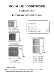
ROOM AIR CONDITIONER OUTDOOR UNIT INSTALLATION INSTRUCTIONS AU142AEEAA AU182AEEAA CONTENTS Name of Parts 1 Safety Cautions 2-3 Installation Procedure---------4-13 AU242AGEAA AU282AHEAA AU28NAHEAA AU36NAIEAA AU48NAIEAA AU52NAIEAA AU60NAIEAA No.0010577959 Before using the air conditioner,please read this manual properly for future use. Please keep this manual carefully.
ROOM AIR CONDITIONER OUTDOOR UNIT INSTALLATION INSTRUCTIONS AU142AEEAA AU182AEEAA CONTENTS Name of Parts 1 Safety Cautions 2-3 Installation Procedure---------4-13 AU242AGEAA AU282AHEAA AU28NAHEAA AU36NAIEAA AU48NAIEAA AU52NAIEAA AU60NAIEAA No.0010577959 Before using the air conditioner,please read this manual properly for future use. Please keep this manual carefully.
User Manual
Page 3
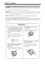
... to operate the airconditioner correctly. If the conditioner is not repaired, the unit may cause water leak, electrical shock and fire hazard. 2 In such case, to conform with the following information in severe consequences of death or serious injuries. If the damaged base is transferred to the new user, this manual should be checked at any time when needed. Incorrect maintenance and repairment may...
... to operate the airconditioner correctly. If the conditioner is not repaired, the unit may cause water leak, electrical shock and fire hazard. 2 In such case, to conform with the following information in severe consequences of death or serious injuries. If the damaged base is transferred to the new user, this manual should be checked at any time when needed. Incorrect maintenance and repairment may...
User Manual
Page 4
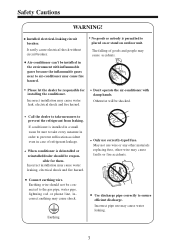
.... May not use correctly-typed fuse. Connect earthing wire. Use discharge pipe correctly to prevent the refrigerant from leaking. Incorrect pipe use may cause water leak, electrical shock and fire hazard. Please let the dealer be installed in case of goods and people may cause shock. Don't operate the air-conditioner with inflammable gases because the inflammable gases near to placed on or stand on outdoor unit. Call the...
.... May not use correctly-typed fuse. Connect earthing wire. Use discharge pipe correctly to prevent the refrigerant from leaking. Incorrect pipe use may cause water leak, electrical shock and fire hazard. Please let the dealer be installed in case of goods and people may cause shock. Don't operate the air-conditioner with inflammable gases because the inflammable gases near to placed on or stand on outdoor unit. Call the...
User Manual
Page 5
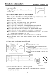
.... Mount guide-louvers to avoid short circuiting. (1) Open space requirement around the unit Air inlet L3 L2 500 Air (Servicing inlet space) Air outlet L1 Note : (1). Edging 2. Place surrounded at the same time, obtain a consent from the unit top (4).Don't block the surroundings of electric wires from other heat sources. Fix the parts with strong winds. Place where air circulates. Place where there is needed for...
.... Mount guide-louvers to avoid short circuiting. (1) Open space requirement around the unit Air inlet L3 L2 500 Air (Servicing inlet space) Air outlet L1 Note : (1). Edging 2. Place surrounded at the same time, obtain a consent from the unit top (4).Don't block the surroundings of electric wires from other heat sources. Fix the parts with strong winds. Place where air circulates. Place where there is needed for...
User Manual
Page 6
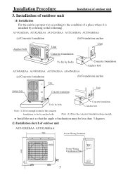
... room for the concrete foundation to fix by referring to the condition of outdoor unit (1) Installation Fix the unit in a proper way according to the following . Installation of a place where it is installed by anchor bolts. Install the unit so that the angle of inclination must be less than 3 degrees. (2) Installation sketch of outdoor unit 3. Installation Procedure Installation of outdoor unit AU142AEEAA AU182AEEAA 780 Power Wiring Terminal 640 25 Power Wiring Distribution Hole...
... room for the concrete foundation to fix by referring to the condition of outdoor unit (1) Installation Fix the unit in a proper way according to the following . Installation of a place where it is installed by anchor bolts. Install the unit so that the angle of inclination must be less than 3 degrees. (2) Installation sketch of outdoor unit 3. Installation Procedure Installation of outdoor unit AU142AEEAA AU182AEEAA 780 Power Wiring Terminal 640 25 Power Wiring Distribution Hole...

User Manual
Page 7
Installation Procedure Installation of outdoor unit 270 500 AU242AGEAA 810 Power Wiring Terminal Power Wiring Distribution Hole 680 580 315 288 AU282AHEAA AU28NAHEAA 948 Power Wiring Terminal Power Wiring Distribution Hole 580 380 840 25 340 6
Installation Procedure Installation of outdoor unit 270 500 AU242AGEAA 810 Power Wiring Terminal Power Wiring Distribution Hole 680 580 315 288 AU282AHEAA AU28NAHEAA 948 Power Wiring Terminal Power Wiring Distribution Hole 580 380 840 25 340 6
User Manual
Page 8
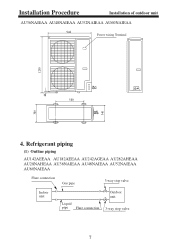
Installation Procedure Installation of outdoor unit AU36NAIEAA AU48NAIEAA AU52NAIEAA AU60NAIEAA 948 Power wiring Terminal 380 1250 25 340 580 4. Refrigerant piping (1) Outline piping AU142AEEAA AU182AEEAA AU242AGEAA AU282AHEAA AU28NAHEAA AU36NAIEAA AU48NAIEAA AU52NAIEAA AU60NAIEAA Flare connection Gas pipe 3-way stop valve Indoor unit Liquid pipe Flare connection Outdoor unit 3-way stop valve 7
Installation Procedure Installation of outdoor unit AU36NAIEAA AU48NAIEAA AU52NAIEAA AU60NAIEAA 948 Power wiring Terminal 380 1250 25 340 580 4. Refrigerant piping (1) Outline piping AU142AEEAA AU182AEEAA AU242AGEAA AU282AHEAA AU28NAHEAA AU36NAIEAA AU48NAIEAA AU52NAIEAA AU60NAIEAA Flare connection Gas pipe 3-way stop valve Indoor unit Liquid pipe Flare connection Outdoor unit 3-way stop valve 7
User Manual
Page 9
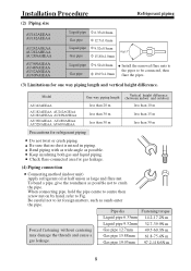
.... Installation Procedure (2) Piping size Refrigerant piping AU142AEEAA AU182AEEAA AU242AGEAA AU282AHEAA AU28NAHEAA AU36NAIEAA AU48NAIEAA AU52ANIEAA AU60NAIEAA Liquid pipe Gas pipe Liquid pipe Gas pipe Liquid pipe Gas pipe 6.35x0.8mm 12.7x1.0mm 9.52x0.8mm 15.88x1.0mm 90+0.5 9.52x0.8mm 19.05x1.0mm Install the removed flare nuts to the pipes to be connected, then flare the pipes. (3) Limitations for refrigerant piping Do not twist or crush piping. Model AU142AEEAA AU182AEEAA...
.... Installation Procedure (2) Piping size Refrigerant piping AU142AEEAA AU182AEEAA AU242AGEAA AU282AHEAA AU28NAHEAA AU36NAIEAA AU48NAIEAA AU52ANIEAA AU60NAIEAA Liquid pipe Gas pipe Liquid pipe Gas pipe Liquid pipe Gas pipe 6.35x0.8mm 12.7x1.0mm 9.52x0.8mm 15.88x1.0mm 90+0.5 9.52x0.8mm 19.05x1.0mm Install the removed flare nuts to the pipes to be connected, then flare the pipes. (3) Limitations for refrigerant piping Do not twist or crush piping. Model AU142AEEAA AU182AEEAA...
User Manual
Page 10
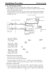
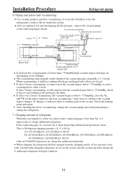
... joint use sense of ambient temperature will make 0.01MPa(0.1kg/cm2g) pressure change. After confirming the leaking point, welding it shall perform air tightness test. Checking the leaking point In the first to prevent the nitrogen entering the circulation system of refrigerant pipe, it again or tighten the nut tightly again. 9 It shall be found . Installation Procedure Refrigerant piping 5. Air discharging method...
... joint use sense of ambient temperature will make 0.01MPa(0.1kg/cm2g) pressure change. After confirming the leaking point, welding it shall perform air tightness test. Checking the leaking point In the first to prevent the nitrogen entering the circulation system of refrigerant pipe, it again or tighten the nut tightly again. 9 It shall be found . Installation Procedure Refrigerant piping 5. Air discharging method...
User Manual
Page 11
... additional refrigerant in COOLING operation can be confirmed both gas and liquid side valves are closed (Liquid side) It shall use the refrigerant to remove the air inside the system. Check the leaking point and repair. Low pressure peizometer High pressure peizometer Indoor Outdoor 3-way valve totally closed (Gas side) V L VH Meter separator Completely tightened Flare part Completely tightened Flare part Discharging valve P Vacuum pump Indoor units Outdoor units...
... additional refrigerant in COOLING operation can be confirmed both gas and liquid side valves are closed (Liquid side) It shall use the refrigerant to remove the air inside the system. Check the leaking point and repair. Low pressure peizometer High pressure peizometer Indoor Outdoor 3-way valve totally closed (Gas side) V L VH Meter separator Completely tightened Flare part Completely tightened Flare part Discharging valve P Vacuum pump Indoor units Outdoor units...
User Manual
Page 12
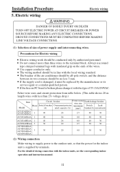
... in line with less than three wires to the outdoor unit, so that the power for Electric wiring Electric wiring work should be conducted only by terminals. Select wire sizes and circuit protection from table below. (This table shows 20 m length wires with the local wiring standard. For the detailed wiring connection with the type of the air conditioner should be all-pole switch; GROUND CONNECTIONS MUST BE COMPLETED...
... in line with less than three wires to the outdoor unit, so that the power for Electric wiring Electric wiring work should be conducted only by terminals. Select wire sizes and circuit protection from table below. (This table shows 20 m length wires with the local wiring standard. For the detailed wiring connection with the type of the air conditioner should be all-pole switch; GROUND CONNECTIONS MUST BE COMPLETED...
User Manual
Page 13
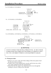
..., AU48NAIEAA, AU52NAIEAA, AU60NAIEAA To Indoor Unit R S TN 1 2 3 Y/G OUTDOOR UNIT TERMINAL BLOCK POWER SUPPLY: 380-400V, 3N~, 50Hz FIG.3 WARNING DO NOT CONNECT THE NEUTRAL WIRE N TO R , S OR T PHASE. INTERCONNECTING WIRES MUST BE WIRED ACCORDING TO FIG.1 FIG.2 FIG.3.INCORRECT WIRING CAUSE EQUIPMENT DAMAGE. (3) Wiring procedure 1) Remove set screws on the side before taking off the front panel toward the direction shown in figure. 2) Connect...
..., AU48NAIEAA, AU52NAIEAA, AU60NAIEAA To Indoor Unit R S TN 1 2 3 Y/G OUTDOOR UNIT TERMINAL BLOCK POWER SUPPLY: 380-400V, 3N~, 50Hz FIG.3 WARNING DO NOT CONNECT THE NEUTRAL WIRE N TO R , S OR T PHASE. INTERCONNECTING WIRES MUST BE WIRED ACCORDING TO FIG.1 FIG.2 FIG.3.INCORRECT WIRING CAUSE EQUIPMENT DAMAGE. (3) Wiring procedure 1) Remove set screws on the side before taking off the front panel toward the direction shown in figure. 2) Connect...
User Manual
Page 14
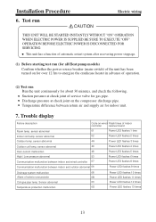
... breaker (main switch) of the unit has been turned on for gas pipe. Suction pressure at check joint on wired Flash times of service valve for over 12 hrs to energize the crankcase heater in advance of exterior annunciator Coil gas pipe temp. Discharge pressure at check joint of indoor controller receiver board 01 Power LED flashes 1 time 02 Power LED flashes 2 times 4A Power LED flashes 3 times Outdoor coil temp. sensor abnormal Code on the compressor...
... breaker (main switch) of the unit has been turned on for gas pipe. Suction pressure at check joint on wired Flash times of service valve for over 12 hrs to energize the crankcase heater in advance of exterior annunciator Coil gas pipe temp. Discharge pressure at check joint of indoor controller receiver board 01 Power LED flashes 1 time 02 Power LED flashes 2 times 4A Power LED flashes 3 times Outdoor coil temp. sensor abnormal Code on the compressor...

User Manual
Page 15
Address: Haier Garden, Qianwangang Road, Economic Development Zone, Qingdao, Shandong 266555, P.R.China Web Site: http://www.haier.com HAIER GROUP Qingdao Haier Air Conditioner Electric Co., Ltd.
Address: Haier Garden, Qianwangang Road, Economic Development Zone, Qingdao, Shandong 266555, P.R.China Web Site: http://www.haier.com HAIER GROUP Qingdao Haier Air Conditioner Electric Co., Ltd.


