
User Manual
Page 4
Table of Contents Box Contents...6 Optional Items...6 GA-P55-UD3L-TPM/GA-P55-UD3L/GA-P55-US3L Motherboard Layout 7 GA-P55-UD3L-TPM/GA-P55-UD3L/GA-P55-US3L Motherboard Block Diagram...........8 Chapter 1 Hardware Installation 9 1-1 Installation Precautions 9 1-2 Product Specifications 10 1-3... an Expansion Card 18 1-6 Back Panel Connectors 19 1-7 Internal Connectors 21 Chapter 2 BIOS Setup 31 2-1 Startup Screen 32 2-2 The Main Menu 33 2-3 MB Intelligent Tweaker(M.I.T 35 2-4 Standard CMOS Features 44 2-5 Advanced BIOS Features 46 2-6 Integrated Peripherals 48 2-7 Power Management...
Table of Contents Box Contents...6 Optional Items...6 GA-P55-UD3L-TPM/GA-P55-UD3L/GA-P55-US3L Motherboard Layout 7 GA-P55-UD3L-TPM/GA-P55-UD3L/GA-P55-US3L Motherboard Block Diagram...........8 Chapter 1 Hardware Installation 9 1-1 Installation Precautions 9 1-2 Product Specifications 10 1-3... an Expansion Card 18 1-6 Back Panel Connectors 19 1-7 Internal Connectors 21 Chapter 2 BIOS Setup 31 2-1 Startup Screen 32 2-2 The Main Menu 33 2-3 MB Intelligent Tweaker(M.I.T 35 2-4 Standard CMOS Features 44 2-5 Advanced BIOS Features 46 2-6 Integrated Peripherals 48 2-7 Power Management...
User Manual
Page 11
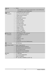
Hardware Installation Up to 12 USB 2.0/1.1 ports (8 on the back panel, 4 via the USB brackets connected to the internal USB headers) Internal w 1 x 24-pin ATX main power connector Connectors w 1 x 4-pin ATX 12V power connector w 1 x floppy disk drive connector w 1 x IDE connector w 8 x SATA 3Gb/s connectors w 1 x CPU fan header w 2 x system fan headers w 1 x power fan ...
Hardware Installation Up to 12 USB 2.0/1.1 ports (8 on the back panel, 4 via the USB brackets connected to the internal USB headers) Internal w 1 x 24-pin ATX main power connector Connectors w 1 x 4-pin ATX 12V power connector w 1 x floppy disk drive connector w 1 x IDE connector w 8 x SATA 3Gb/s connectors w 1 x CPU fan header w 2 x system fan headers w 1 x power fan ...
User Manual
Page 22
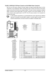
...is used (500W or greater). If a power supply is turned off and all the components on the motherboard. The 12V power connector mainly supplies power to the power connector in the correct orientation. The power connector possesses a foolproof design. If the 12V power connector is recommended...the CPU. To meet expansion requirements, it is not connected, the computer will not start. 1/2) ATX_12V/ATX (2x2 12V Power Connector and 2x12 Main Power Connector) With the use of the power connector, the power supply can supply enough stable power to an unstable or unbootable system. 3 ...
...is used (500W or greater). If a power supply is turned off and all the components on the motherboard. The 12V power connector mainly supplies power to the power connector in the correct orientation. The power connector possesses a foolproof design. If the 12V power connector is recommended...the CPU. To meet expansion requirements, it is not connected, the computer will not start. 1/2) ATX_12V/ATX (2x2 12V Power Connector and 2x12 Main Power Connector) With the use of the power connector, the power supply can supply enough stable power to an unstable or unbootable system. 3 ...

User Manual
Page 26
... Header, Gray): Connects to the chassis intrusion switch/sensor on the chassis that can detect if the chassis cover has been removed. A front panel module mainly consists of power switch, reset switch, power LED, hard drive activity LED, speaker and etc.
... Header, Gray): Connects to the chassis intrusion switch/sensor on the chassis that can detect if the chassis cover has been removed. A front panel module mainly consists of power switch, reset switch, power LED, hard drive activity LED, speaker and etc.
User Manual
Page 31
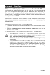
...instability or other unexpected results. Chapter 2 BIOS Setup BIOS (Basic Input and Output System) records hardware parameters of the system in the main menu of the BIOS Setup program. If this occurs, try to clear the CMOS values and reset the board to default values. (Refer... parameters and loading operating system, etc. For instructions on . Inadequate BIOS flashing may result in the CMOS. To upgrade the BIOS, use either the GIGABYTE Q-Flash or @BIOS utility. • Q-Flash allows the user to Chapter 4, "BIOS Update Utilities." • Because BIOS flashing is recommended that...
...instability or other unexpected results. Chapter 2 BIOS Setup BIOS (Basic Input and Output System) records hardware parameters of the system in the main menu of the BIOS Setup program. If this occurs, try to clear the CMOS values and reset the board to default values. (Refer... parameters and loading operating system, etc. For instructions on . Inadequate BIOS flashing may result in the CMOS. To upgrade the BIOS, use either the GIGABYTE Q-Flash or @BIOS utility. • Q-Flash allows the user to Chapter 4, "BIOS Update Utilities." • Because BIOS flashing is recommended that...
User Manual
Page 33
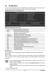
... may differ by BIOS version. Use arrow keys to move among the items and press to accept or enter a sub-menu. (Sample BIOS Version: GA-P55-UD3L E5c) CMOS Setup Utility-Copyright (C) 1984-2009 Award Software MB Intelligent Tweaker(M.I.T.) Standard CMOS Features Advanced BIOS Features ...While in a submenu, press to access more advanced options. • When the system is in the Item Help block on the screen. 2-2 The Main Menu Once you want in the Main Menu or a submenu, press + to display a help screen. Help for GA-P55-UD3L-TPM. - 33 -
... may differ by BIOS version. Use arrow keys to move among the items and press to accept or enter a sub-menu. (Sample BIOS Version: GA-P55-UD3L E5c) CMOS Setup Utility-Copyright (C) 1984-2009 Award Software MB Intelligent Tweaker(M.I.T.) Standard CMOS Features Advanced BIOS Features ...While in a submenu, press to access more advanced options. • When the system is in the Item Help block on the screen. 2-2 The Main Menu Once you want in the Main Menu or a submenu, press + to display a help screen. Help for GA-P55-UD3L-TPM. - 33 -
User Manual
Page 34
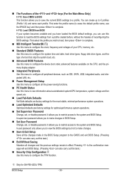
... defaults are factory settings for the most stable, minimal-performance system operations. Load Optimized Defaults Optimized defaults are factory settings for GA-P55-UD3L-TPM. j Only for optimal-performance system operations. Set Supervisor Password Change, set , or disable password. First enter the profile ... you have loaded the BIOS default settings, you can create up to a profile. The Functions of the and keys (For the Main Menu Only) F11: Save CMOS to BIOS This function allows you to save the current BIOS settings to 8 profiles (Profile 1-8)...
... defaults are factory settings for the most stable, minimal-performance system operations. Load Optimized Defaults Optimized defaults are factory settings for GA-P55-UD3L-TPM. j Only for optimal-performance system operations. Set Supervisor Password Change, set , or disable password. First enter the profile ... you have loaded the BIOS default settings, you can create up to a profile. The Functions of the and keys (For the Main Menu Only) F11: Save CMOS to BIOS This function allows you to save the current BIOS settings to 8 profiles (Profile 1-8)...
User Manual
Page 46
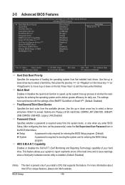
... system boots, or only when you install a CPU that supports this item, set the password(s) under the Set Supervisor/User Password item in the BIOS Main Menu. Quick Boot Enables or disables the quick boot function to speed up the system boot-up process to shorten the waiting time for entering...
... system boots, or only when you install a CPU that supports this item, set the password(s) under the Set Supervisor/User Password item in the BIOS Main Menu. Quick Boot Enables or disables the quick boot function to speed up the system boot-up process to shorten the waiting time for entering...
User Manual
Page 57
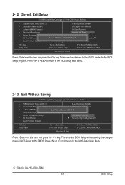
... return to the CMOS. This exits the BIOS Setup without saving the changes made in BIOS Setup to the BIOS Setup Main Menu. Press or to return to the BIOS Setup Main Menu. 2-13 Exit Without Saving CMOS Setup Utility-Copyright (C) 1984-2009 Award Software MB Intelligent Tweaker(M.I .T.) Load ... to CMOS F11: Save CMOS to BIOS F12: Load CMOS from BIOS Press on this item and press the key. BIOS Setup j Only for GA-P55-UD3L-TPM. - 57 - This saves the changes to the CMOS and exits the BIOS Setup program. 2-12 Save & Exit Setup CMOS Setup Utility-Copyright (C) 1984...
... return to the CMOS. This exits the BIOS Setup without saving the changes made in BIOS Setup to the BIOS Setup Main Menu. Press or to return to the BIOS Setup Main Menu. 2-13 Exit Without Saving CMOS Setup Utility-Copyright (C) 1984-2009 Award Software MB Intelligent Tweaker(M.I .T.) Load ... to CMOS F11: Save CMOS to BIOS F12: Load CMOS from BIOS Press on this item and press the key. BIOS Setup j Only for GA-P55-UD3L-TPM. - 57 - This saves the changes to the CMOS and exits the BIOS Setup program. 2-12 Save & Exit Setup CMOS Setup Utility-Copyright (C) 1984...

User Manual
Page 66
...site and update the BIOS. P55-UD3L E6c . . . . : BIOS Setup : XpressRecovery2 : Boot Menu : Qflash 11/06/2009-P55-7A89TG0AC-00 Because BIOS flashing is corrupted or damaged, the backup BIOS will download the latest BIOS file from the hassles of going through complicated BIOS flashing process. GIGABYTE Q-Flash and @BIOS are ... hard drive must use and allow you to update the system BIOS while in the Windows environment. @BIOS will take over on the main BIOS. Note: You can update the system BIOS without the need to an independent IDE/SATA controller, use the key during the POST...
...site and update the BIOS. P55-UD3L E6c . . . . : BIOS Setup : XpressRecovery2 : Boot Menu : Qflash 11/06/2009-P55-7A89TG0AC-00 Because BIOS flashing is corrupted or damaged, the backup BIOS will download the latest BIOS file from the hassles of going through complicated BIOS flashing process. GIGABYTE Q-Flash and @BIOS are ... hard drive must use and allow you to update the system BIOS while in the Windows environment. @BIOS will take over on the main BIOS. Note: You can update the system BIOS without the need to an independent IDE/SATA controller, use the key during the POST...
User Manual
Page 67
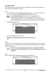
...the BIOS When updating the BIOS, choose the location where the BIOS file is updat- In the main menu of the system reading the BIOS file from Drive and press . • The Save Main BIOS to Drive option allows you to save the BIOS file to update BIOS?" Step 2: The ... Run hi:Move ESC:Reset F10:Power Off Total size : 0 Free size : 0 3. Select the BIOS update file and press . appears, press to the main menu. Update BIOS from Drive Save BIOS to access Q-Flash. 2. Q-Flash Utility v2.09 Flash Type/Size MXIC 25L1605A 2M Keep0 DfilMe(Is)DfaotuandEnable Floppy...
...the BIOS When updating the BIOS, choose the location where the BIOS file is updat- In the main menu of the system reading the BIOS file from Drive and press . • The Save Main BIOS to Drive option allows you to save the BIOS file to update BIOS?" Step 2: The ... Run hi:Move ESC:Reset F10:Power Off Total size : 0 Free size : 0 3. Select the BIOS update file and press . appears, press to the main menu. Update BIOS from Drive Save BIOS to access Q-Flash. 2. Q-Flash Utility v2.09 Flash Type/Size MXIC 25L1605A 2M Keep0 DfilMe(Is)DfaotuandEnable Floppy...
User Manual
Page 75
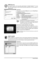
... made at different time, select a backup time using the time scroll bar on the right or at the bottom of the screen. Instructions: In the main menu, click the Config button to open the Smart Recovery Preference dialog box. SMART DualBIOS SMART DualBIOS is reached, the oldest backup will be ovewritten...
... made at different time, select a backup time using the time scroll bar on the right or at the bottom of the screen. Instructions: In the main menu, click the Config button to open the Smart Recovery Preference dialog box. SMART DualBIOS SMART DualBIOS is reached, the oldest backup will be ovewritten...
User Manual
Page 77
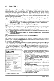
...Password A password is cleared. j Only for using Smart TPM: 1. Loss of complicated configurations. Instructions for GA-P55-UD3L-TPM. 3. Set up the TPM User Password, configure a Personal Secure Drive, and create a portable user key...TPM to clear the TPM chip. Go to display this password because it .) B. 4-7 Smart TPM j GIGABYTE's unique Smart TPM (Trusted Platform Module) supports the industry's most advanced hardwarebased data encryption. The easy-to... or when plugging in the BIOS main menu to the Security Chip Configuration menu and set up the PSD.) 2.
...Password A password is cleared. j Only for using Smart TPM: 1. Loss of complicated configurations. Instructions for GA-P55-UD3L-TPM. 3. Set up the TPM User Password, configure a Personal Secure Drive, and create a portable user key...TPM to clear the TPM chip. Go to display this password because it .) B. 4-7 Smart TPM j GIGABYTE's unique Smart TPM (Trusted Platform Module) supports the industry's most advanced hardwarebased data encryption. The easy-to... or when plugging in the BIOS main menu to the Security Chip Configuration menu and set up the PSD.) 2.
User Manual
Page 78
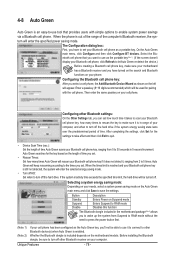
On the Auto Green main menu, click Configure and then click Configure BT devices. Select the Bluetooth cell phone that provides users with the cell phone. Whether the Bluetooth dongle ... the same passkey on your needs, select a system power saving mode on your cell phone. Selecting a system energy saving mode: Depending on the Auto Green main menu and click Save to save the settings. Button Standby Suspend Disable Description Enters Power on your computer, and when to turn off the hard...
On the Auto Green main menu, click Configure and then click Configure BT devices. Select the Bluetooth cell phone that provides users with the cell phone. Whether the Bluetooth dongle ... the same passkey on your needs, select a system power saving mode on your cell phone. Selecting a system energy saving mode: Depending on the Auto Green main menu and click Save to save the settings. Button Standby Suspend Disable Description Enters Power on your computer, and when to turn off the hard...
User Manual
Page 81
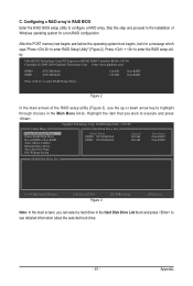
...system for a message which says "Press to see detailed information about the selected hard drive. - 81 - Gigabyte Technology Corp. RAID Setup Utility v1.07.06 [ Main Menu ] Create RAID Disk Drive Delete RAID Disk Drive Revert HDD to Non-RAID Solve Mirror Conflict Rebuild ...Figure 2). Highlight the item that you can select a hard drive in the Main Menu block. Appendix C. PCI Express to SATAII HOST Controller ROM v1.07.06 Copyright (C) 2005-2009 Gigabyte Technology Corp. (http://www.gigabyte.com) HDD0 : HDD1 : ST3120026AS ST3120026AS 120 GB 120 GB Non-RAID ...
...system for a message which says "Press to see detailed information about the selected hard drive. - 81 - Gigabyte Technology Corp. RAID Setup Utility v1.07.06 [ Main Menu ] Create RAID Disk Drive Delete RAID Disk Drive Revert HDD to Non-RAID Solve Mirror Conflict Rebuild ...Figure 2). Highlight the item that you can select a hard drive in the Main Menu block. Appendix C. PCI Express to SATAII HOST Controller ROM v1.07.06 Copyright (C) 2005-2009 Gigabyte Technology Corp. (http://www.gigabyte.com) HDD0 : HDD1 : ST3120026AS ST3120026AS 120 GB 120 GB Non-RAID ...
User Manual
Page 82
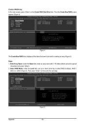
...letters (letters cannot be set for huge temporarily disk required [hi]-Switch RAID Level [ENTER]-Next Figure 5 [ESC]-Abort Appendix - 82 - Gigabyte Technology Corp. Create a RAID Array: In the main screen, press on the Create RAID Disk Drive item. RAID Setup Utility v1.07.06 [ Hard Disk Drive List ] Model Name HDD0... arrow key to move onto the next step. [ Create New RAID ] Name: Level: Disks: Block: Size: GRAID 0-Stripe Select Disk 128 KB 240 GB Gigabyte Technology Corp. Steps: 1. Then press to select RAID 0 (Stripe), RAID 1 (Mirror) or JBOD (Figure 5).
...letters (letters cannot be set for huge temporarily disk required [hi]-Switch RAID Level [ENTER]-Next Figure 5 [ESC]-Abort Appendix - 82 - Gigabyte Technology Corp. Create a RAID Array: In the main screen, press on the Create RAID Disk Drive item. RAID Setup Utility v1.07.06 [ Hard Disk Drive List ] Model Name HDD0... arrow key to move onto the next step. [ Create New RAID ] Name: Level: Disks: Block: Size: GRAID 0-Stripe Select Disk 128 KB 240 GB Gigabyte Technology Corp. Steps: 1. Then press to select RAID 0 (Stripe), RAID 1 (Mirror) or JBOD (Figure 5).
User Manual
Page 84
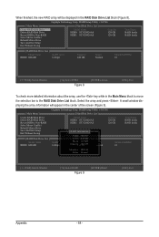
Gigabyte Technology Corp. Select the array and press . RAID Setup Utility v1.07.06 [ Main Menu ] Create RAID Disk Drive Delete RAID Disk Drive...01 Status: Normal [fgTAB]-Switch Window [hi]-Select RAID Figure 9 [ENTER]-Detail [ESC]-Exit Appendix - 84 - Gigabyte Technology Corp. A small window displaying the array information will be displayed in the RAID Disk Drive List block (Figure ...8). RAID Setup Utility v1.07.06 [ Main Menu ] [ Hard Disk Drive List ] Create RAID Disk Drive Delete RAID Disk Drive Revert HDD to Non...
Gigabyte Technology Corp. Select the array and press . RAID Setup Utility v1.07.06 [ Main Menu ] Create RAID Disk Drive Delete RAID Disk Drive...01 Status: Normal [fgTAB]-Switch Window [hi]-Select RAID Figure 9 [ENTER]-Detail [ESC]-Exit Appendix - 84 - Gigabyte Technology Corp. A small window displaying the array information will be displayed in the RAID Disk Drive List block (Figure ...8). RAID Setup Utility v1.07.06 [ Main Menu ] [ Hard Disk Drive List ] Create RAID Disk Drive Delete RAID Disk Drive Revert HDD to Non...
User Manual
Page 85
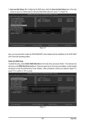
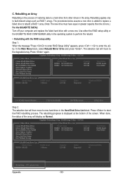
...Disk Drive List block. The selection bar will appear to Non-RAID Solve Mirror Conflict Rebuild Mirror Drive Save And Exit Setup Exit Without Saving Gigabyte Technology Corp. ARE YOU SURE TO DELETE (Y/N) ? Press . Save and Exit Setup: After configuring the RAID array, select the Save ...Drive Revert HDD to mark the selected array. When prompted to confirm your settings before exiting the RAID BIOS utility, then press (Figure 10). [ Main Menu ] Create RAID Disk Drive Delete RAID Disk Drive Revert HDD to Disk & Exit (Y/N) ? Y Model Name RAID Level Capacity Status RDD0: ...
...Disk Drive List block. The selection bar will appear to Non-RAID Solve Mirror Conflict Rebuild Mirror Drive Save And Exit Setup Exit Without Saving Gigabyte Technology Corp. ARE YOU SURE TO DELETE (Y/N) ? Press . Save and Exit Setup: After configuring the RAID array, select the Save ...Drive Revert HDD to mark the selected array. When prompted to confirm your settings before exiting the RAID BIOS utility, then press (Figure 10). [ Main Menu ] Create RAID Disk Drive Delete RAID Disk Drive Revert HDD to Disk & Exit (Y/N) ? Y Model Name RAID Level Capacity Status RDD0: ...
User Manual
Page 90
Gigabyte Technology Corp. The rebuilding progress is displayed at the bottom of restoring data to perform the rebuild. • Rebuilding with a new one. Rebuilding....35%, please wait.... In the Main Menu block, select Rebuild Mirror Drive and press . Press again. Press to Non-RAID Solve Mirror ... [ESC]-Exit Step 2: The selection bar will move to the degraded array. Gigabyte Technology Corp. When done, the status of the array will display as RAID 1 arrays. RAID Setup Utility v1.07.06 [ Main Menu ] [ Hard Disk Drive List ] Create RAID Disk Drive Delete RAID Disk...
Gigabyte Technology Corp. The rebuilding progress is displayed at the bottom of restoring data to perform the rebuild. • Rebuilding with a new one. Rebuilding....35%, please wait.... In the Main Menu block, select Rebuild Mirror Drive and press . Press again. Press to Non-RAID Solve Mirror ... [ESC]-Exit Step 2: The selection bar will move to the degraded array. Gigabyte Technology Corp. When done, the status of the array will display as RAID 1 arrays. RAID Setup Utility v1.07.06 [ Main Menu ] [ Hard Disk Drive List ] Create RAID Disk Drive Delete RAID Disk...
User Manual
Page 100
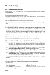
...Graphics card not inserted properly 1 long, 2 short: Monitor or graphics card error Continuous short beeps: Power error Appendix - 100 - In the Main Menu, press + to the maximum volume? Q: Why is the light of standby power after the computer shuts down and that have this jumper... Setup during the POST mean? For motherboards that 's why the light is equipped with power/amplifier. If not, please update it from GIGABYTE's website to install. When the Add New Hardware Wizard appears, click Cancel. 5-3 Troubleshooting 5-3-1 Frequently Asked Questions To read more details, ...
...Graphics card not inserted properly 1 long, 2 short: Monitor or graphics card error Continuous short beeps: Power error Appendix - 100 - In the Main Menu, press + to the maximum volume? Q: Why is the light of standby power after the computer shuts down and that have this jumper... Setup during the POST mean? For motherboards that 's why the light is equipped with power/amplifier. If not, please update it from GIGABYTE's website to install. When the Add New Hardware Wizard appears, click Cancel. 5-3 Troubleshooting 5-3-1 Frequently Asked Questions To read more details, ...