
User Manual
Page 4
Table of Contents Box Contents...6 Optional Items...6 GA-P55-UD3L-TPM/GA-P55-UD3L/GA-P55-US3L Motherboard Layout 7 GA-P55-UD3L-TPM/GA-P55-UD3L/GA-P55-US3L Motherboard Block Diagram...........8 Chapter 1 Hardware Installation 9 1-1 Installation Precautions 9 1-2 Product Specifications 10 1-3... an Expansion Card 18 1-6 Back Panel Connectors 19 1-7 Internal Connectors 21 Chapter 2 BIOS Setup 31 2-1 Startup Screen 32 2-2 The Main Menu 33 2-3 MB Intelligent Tweaker(M.I.T 35 2-4 Standard CMOS Features 44 2-5 Advanced BIOS Features 46 2-6 Integrated Peripherals 48 2-7 Power Management...
Table of Contents Box Contents...6 Optional Items...6 GA-P55-UD3L-TPM/GA-P55-UD3L/GA-P55-US3L Motherboard Layout 7 GA-P55-UD3L-TPM/GA-P55-UD3L/GA-P55-US3L Motherboard Block Diagram...........8 Chapter 1 Hardware Installation 9 1-1 Installation Precautions 9 1-2 Product Specifications 10 1-3... an Expansion Card 18 1-6 Back Panel Connectors 19 1-7 Internal Connectors 21 Chapter 2 BIOS Setup 31 2-1 Startup Screen 32 2-2 The Main Menu 33 2-3 MB Intelligent Tweaker(M.I.T 35 2-4 Standard CMOS Features 44 2-5 Advanced BIOS Features 46 2-6 Integrated Peripherals 48 2-7 Power Management...
User Manual
Page 11
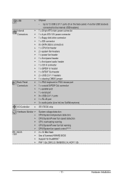
... Chipset - Up to 12 USB 2.0/1.1 ports (8 on the back panel, 4 via the USB brackets connected to the internal USB headers) Internal w 1 x 24-pin ATX main power connector Connectors w 1 x 4-pin ATX 12V power connector w 1 x floppy disk drive connector w 1 x IDE connector w 8 x SATA 3Gb/s connectors w 1 x CPU fan header w 2 x system fan headers w 1 x power fan...
... Chipset - Up to 12 USB 2.0/1.1 ports (8 on the back panel, 4 via the USB brackets connected to the internal USB headers) Internal w 1 x 24-pin ATX main power connector Connectors w 1 x 4-pin ATX 12V power connector w 1 x floppy disk drive connector w 1 x IDE connector w 8 x SATA 3Gb/s connectors w 1 x CPU fan header w 2 x system fan headers w 1 x power fan...
User Manual
Page 22
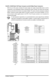
...the power supply is not connected, the computer will not start. The power connector possesses a foolproof design. The 12V power connector mainly supplies power to the power connector in the correct orientation. If the 12V power connector is turned off and all the components on... meet expansion requirements, it is used that can withstand high power consumption be used (500W or greater). 1/2) ATX_12V/ATX (2x2 12V Power Connector and 2x12 Main Power Connector) With the use of the power connector, the power supply can lead to an unstable or unbootable system. 3 4 1 2 ATX_12V ATX_12V: ...
...the power supply is not connected, the computer will not start. The power connector possesses a foolproof design. The 12V power connector mainly supplies power to the power connector in the correct orientation. If the 12V power connector is turned off and all the components on... meet expansion requirements, it is used that can withstand high power consumption be used (500W or greater). 1/2) ATX_12V/ATX (2x2 12V Power Connector and 2x12 Main Power Connector) With the use of the power connector, the power supply can lead to an unstable or unbootable system. 3 4 1 2 ATX_12V ATX_12V: ...

User Manual
Page 26
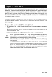
.../PWR (Message/Power/Sleep LED, Yellow/Purple): System Status LED Connects to the hard drive activity LED on the chassis front panel. A front panel module mainly consists of power switch, reset switch, power LED, hard drive activity LED, speaker and etc. Speaker Power Switch Message/Power/ Sleep LED 20 19 SPEAK...
.../PWR (Message/Power/Sleep LED, Yellow/Purple): System Status LED Connects to the hard drive activity LED on the chassis front panel. A front panel module mainly consists of power switch, reset switch, power LED, hard drive activity LED, speaker and etc. Speaker Power Switch Message/Power/ Sleep LED 20 19 SPEAK...
User Manual
Page 31
... off, the battery on the motherboard. To see more advanced BIOS Setup menu options, you can press + in the main menu of the BIOS Setup program. To upgrade the BIOS, use either the GIGABYTE Q-Flash or @BIOS utility. • Q-Flash allows the user to activate certain system features. When the power is...
... off, the battery on the motherboard. To see more advanced BIOS Setup menu options, you can press + in the main menu of the BIOS Setup program. To upgrade the BIOS, use either the GIGABYTE Q-Flash or @BIOS utility. • Q-Flash allows the user to activate certain system features. When the power is...
User Manual
Page 33
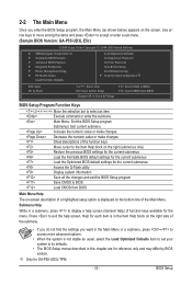
... for the menu. Use arrow keys to move among the items and press to accept or enter a sub-menu. (Sample BIOS Version: GA-P55-UD3L E5c) CMOS Setup Utility-Copyright (C) 1984-2009 Award Software MB Intelligent Tweaker(M.I.T.) Standard CMOS Features Advanced BIOS Features ...exit the help screen (General Help) of function keys available for GA-P55-UD3L-TPM. - 33 - Submenu Help While in a submenu, press to display a help screen. BIOS Setup 2-2 The Main Menu Once you want in the Main Menu or a submenu, press + to access more advanced options. •...
... for the menu. Use arrow keys to move among the items and press to accept or enter a sub-menu. (Sample BIOS Version: GA-P55-UD3L E5c) CMOS Setup Utility-Copyright (C) 1984-2009 Award Software MB Intelligent Tweaker(M.I.T.) Standard CMOS Features Advanced BIOS Features ...exit the help screen (General Help) of function keys available for GA-P55-UD3L-TPM. - 33 - Submenu Help While in a submenu, press to display a help screen. BIOS Setup 2-2 The Main Menu Once you want in the Main Menu or a submenu, press + to access more advanced options. •...
User Manual
Page 34
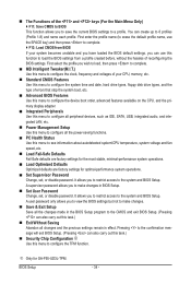
...performance system operations. Set Supervisor Password Change, set , or disable password. The Functions of the and keys (For the Main Menu Only) F11: Save CMOS to BIOS This function allows you to save the current BIOS settings to the system and BIOS Setup... defaults are factory settings for the most stable, minimal-performance system operations. Load Optimized Defaults Optimized defaults are factory settings for GA-P55-UD3L-TPM. BIOS Setup - 34 - First select the profile you wish to load, then press to complete. MB Intelligent Tweaker(M.I.T.)...
...performance system operations. Set Supervisor Password Change, set , or disable password. The Functions of the and keys (For the Main Menu Only) F11: Save CMOS to BIOS This function allows you to save the current BIOS settings to the system and BIOS Setup... defaults are factory settings for the most stable, minimal-performance system operations. Load Optimized Defaults Optimized defaults are factory settings for GA-P55-UD3L-TPM. BIOS Setup - 34 - First select the profile you wish to load, then press to complete. MB Intelligent Tweaker(M.I.T.)...
User Manual
Page 46
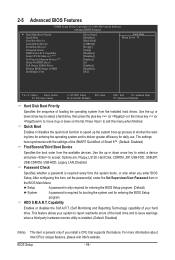
Press to exit this item, set the password(s) under the Set Supervisor/User Password item in the BIOS Main Menu. Use the up process to shorten the waiting time for entering the operating system and to speed up the system boot-up or down ...
Press to exit this item, set the password(s) under the Set Supervisor/User Password item in the BIOS Main Menu. Use the up process to shorten the waiting time for entering the operating system and to speed up the system boot-up or down ...
User Manual
Page 57
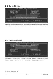
Press or to return to the CMOS. This exits the BIOS Setup without saving the changes made in BIOS Setup to the BIOS Setup Main Menu. j Only for GA-P55-UD3L-TPM. - 57 - This saves the changes to BIOS F12: Load CMOS from BIOS Press on this item and press the key....: Save CMOS to BIOS F12: Load CMOS from BIOS Press on this item and press the key. Press or to return to the BIOS Setup Main Menu. 2-13 Exit Without Saving CMOS Setup Utility-Copyright (C) 1984-2009 Award Software MB Intelligent Tweaker(M.I .T.) Load Optimized Defaults Standard CMOS...
Press or to return to the CMOS. This exits the BIOS Setup without saving the changes made in BIOS Setup to the BIOS Setup Main Menu. j Only for GA-P55-UD3L-TPM. - 57 - This saves the changes to BIOS F12: Load CMOS from BIOS Press on this item and press the key....: Save CMOS to BIOS F12: Load CMOS from BIOS Press on this item and press the key. Press or to return to the BIOS Setup Main Menu. 2-13 Exit Without Saving CMOS Setup Utility-Copyright (C) 1984-2009 Award Software MB Intelligent Tweaker(M.I .T.) Load Optimized Defaults Standard CMOS...

User Manual
Page 66
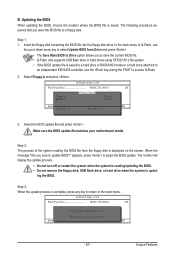
...and update the BIOS. From GIGABYTE's website, download the latest compressed BIOS update file that support DualBIOS have two BIOS onboard, a main BIOS and a backup BIOS. Extract the file and save the new BIOS file (e.g. During the POST, press the key to your motherboard model. 2. P55-UD3L E6c . . . . ...: BIOS Setup : XpressRecovery2 : Boot Menu : Qflash 11/06/2009-P55-7A89TG0AC-00 Because BIOS flashing...
...and update the BIOS. From GIGABYTE's website, download the latest compressed BIOS update file that support DualBIOS have two BIOS onboard, a main BIOS and a backup BIOS. Extract the file and save the new BIOS file (e.g. During the POST, press the key to your motherboard model. 2. P55-UD3L E6c . . . . ...: BIOS Setup : XpressRecovery2 : Boot Menu : Qflash 11/06/2009-P55-7A89TG0AC-00 Because BIOS flashing...
User Manual
Page 67
...SparevsesBaInOySketoy Dtoricvoentinue Enter : Run hi:Move ESC:Reset F10:Power Off - 67 - When the message "Are you to save the BIOS file to the main menu. Update BIOS from Drive Save BIOS to select Update BIOS from the floppy disk is complete, press any key to return to a floppy disk... updating the BIOS, choose the location where the BIOS file is updat- B. Step 1: 1. In the main menu of the system reading the BIOS file from Drive and press . • The Save Main BIOS to Drive option allows you sure to begin the BIOS update. Select the BIOS update file and...
...SparevsesBaInOySketoy Dtoricvoentinue Enter : Run hi:Move ESC:Reset F10:Power Off - 67 - When the message "Are you to save the BIOS file to the main menu. Update BIOS from Drive Save BIOS to select Update BIOS from the floppy disk is complete, press any key to return to a floppy disk... updating the BIOS, choose the location where the BIOS file is updat- B. Step 1: 1. In the main menu of the system reading the BIOS file from Drive and press . • The Save Main BIOS to Drive option allows you sure to begin the BIOS update. Select the BIOS update file and...
User Manual
Page 75
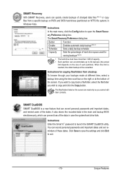
...these dates. Instructions: Enter the Smart 6™ password to open the Smart Recovery Preference dialog box. Unique Features Instructions: In the main menu, click the Config button to launch the SMART DualBIOS utility. The Smart Recovery Preference dialog box: Button Enable Schedule Capacity Function ... screen are read-only so you wish to copy and click the Copy button. It also stores the recorded data in the main and backup BIOS simultaneously, which can record personal passwords and important dates, and remind users of the screen. SMART DualBIOS SMART ...
...these dates. Instructions: Enter the Smart 6™ password to open the Smart Recovery Preference dialog box. Unique Features Instructions: In the main menu, click the Config button to launch the SMART DualBIOS utility. The Smart Recovery Preference dialog box: Button Enable Schedule Capacity Function ... screen are read-only so you wish to copy and click the Copy button. It also stores the recorded data in the main and backup BIOS simultaneously, which can record personal passwords and important dates, and remind users of the screen. SMART DualBIOS SMART ...
User Manual
Page 77
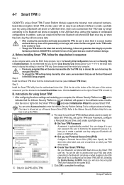
...and set up your computer. • Previously encrypted files will appear in the BIOS main menu to display this password because it does not guarantee data integrity or provide hardware ...select Infineon TPM Driver). Click the Install button on which indicates that is not liable for GA-P55-UD3L-TPM. 3. Double- click the icon or right-click the Smart TPM icon and select Initialization Wizard... you use the Clear Security Chip setting (press + in the notification area. GIGABYTE is configured as the Smart TPM user key. Before installing Smart TPM, follow the steps below ...
...and set up your computer. • Previously encrypted files will appear in the BIOS main menu to display this password because it does not guarantee data integrity or provide hardware ...select Infineon TPM Driver). Click the Install button on which indicates that is not liable for GA-P55-UD3L-TPM. 3. Double- click the icon or right-click the Smart TPM icon and select Initialization Wizard... you use the Clear Security Chip setting (press + in the notification area. GIGABYTE is configured as the Smart TPM user key. Before installing Smart TPM, follow the steps below ...
User Manual
Page 78
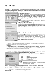
On the Auto Green main menu, click Configure and then click Configure BT devices. Then enter the same passkey on your Bluetooth cell phone as shown on your phone. Selecting a ... device.) Before creating a Bluetooth cell phone key, make sure it is in 5-second increment. Whether the Bluetooth dongle is included depends on the Auto Green main menu and click Save to other Bluetooth device(s) when Auto Green is enabled. Select the Bluetooth cell phone that provides users with the cell phone...
On the Auto Green main menu, click Configure and then click Configure BT devices. Then enter the same passkey on your Bluetooth cell phone as shown on your phone. Selecting a ... device.) Before creating a Bluetooth cell phone key, make sure it is in 5-second increment. Whether the Bluetooth dongle is included depends on the Auto Green main menu and click Save to other Bluetooth device(s) when Auto Green is enabled. Select the Bluetooth cell phone that provides users with the cell phone...
User Manual
Page 81
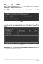
... ITEM Figure 3 [ENTER]-Action [ESC]-Exit Note: In the main screen, you wish to configure a RAID array. Figure 2 In the main screen of Windows operating system for a message which says "Press to see detailed information about the selected hard drive. - 81 - Gigabyte Technology Corp. GIGABYTE Technology Corp. After the POST memory test begins and...
... ITEM Figure 3 [ENTER]-Action [ESC]-Exit Note: In the main screen, you wish to configure a RAID array. Figure 2 In the main screen of Windows operating system for a message which says "Press to see detailed information about the selected hard drive. - 81 - Gigabyte Technology Corp. GIGABYTE Technology Corp. After the POST memory test begins and...
User Manual
Page 82
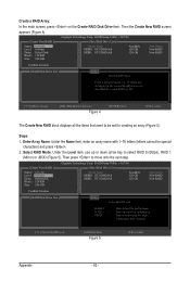
... set for huge temporarily disk required [hi]-Switch RAID Level [ENTER]-Next Figure 5 [ESC]-Abort Appendix - 82 - Then the Create New RAID screen appears (Figure 4). Gigabyte Technology Corp. RAID Setup Utility v1.07.06 [ Hard Disk Drive List ] Model Name HDD0: ST3120026AS HDD1: ST3120026AS Available 120 GB 120 GB Type/Status... RAID Level RAID 0 RAID 1 JBOD Data striped for performance Data mirrored for redundancy Data concatenated for creating an array (Figure 5). Create a RAID Array: In the main screen, press on the Create RAID Disk Drive item.
... set for huge temporarily disk required [hi]-Switch RAID Level [ENTER]-Next Figure 5 [ESC]-Abort Appendix - 82 - Then the Create New RAID screen appears (Figure 4). Gigabyte Technology Corp. RAID Setup Utility v1.07.06 [ Hard Disk Drive List ] Model Name HDD0: ST3120026AS HDD1: ST3120026AS Available 120 GB 120 GB Type/Status... RAID Level RAID 0 RAID 1 JBOD Data striped for performance Data mirrored for redundancy Data concatenated for creating an array (Figure 5). Create a RAID Array: In the main screen, press on the Create RAID Disk Drive item.
User Manual
Page 84
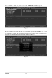
Gigabyte Technology Corp. Gigabyte Technology Corp. RAID Setup Utility v1.07.06 [ Main Menu ] [ Hard Disk Drive List ] Create RAID Disk Drive Delete ...array information will be displayed in the RAID Disk Drive List block (Figure 8). RAID Setup Utility v1.07.06 [ Main Menu ] Create RAID Disk Drive Delete RAID Disk Drive Revert HDD to the RAID Disk Drive List block. Select the... array and press . When finished, the new RAID array will appear in the Main Menu block to move the selection bar to Non-RAID Solve Mirror Conflict Rebuild Mirror Drive Save And Exit...
Gigabyte Technology Corp. Gigabyte Technology Corp. RAID Setup Utility v1.07.06 [ Main Menu ] [ Hard Disk Drive List ] Create RAID Disk Drive Delete ...array information will be displayed in the RAID Disk Drive List block (Figure 8). RAID Setup Utility v1.07.06 [ Main Menu ] Create RAID Disk Drive Delete RAID Disk Drive Revert HDD to the RAID Disk Drive List block. Select the... array and press . When finished, the new RAID array will appear in the Main Menu block to move the selection bar to Non-RAID Solve Mirror Conflict Rebuild Mirror Drive Save And Exit...
User Manual
Page 85
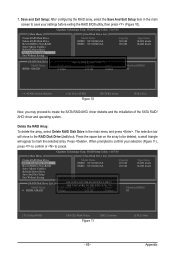
...-RAID Solve Mirror Conflict Rebuild Mirror Drive Save And Exit Setup Exit Without Saving Gigabyte Technology Corp. When prompted to confirm your settings before exiting the RAID BIOS utility, then press (Figure 10). [ Main Menu ] Create RAID Disk Drive Delete RAID Disk Drive Revert HDD to the... RAID Disk Drive List block. a small triangle will move to Non-RAID Solve Mirror Conflict Rebuild Mirror Drive Save And Exit Setup Exit Without Saving Gigabyte Technology Corp. RAID Setup ...
...-RAID Solve Mirror Conflict Rebuild Mirror Drive Save And Exit Setup Exit Without Saving Gigabyte Technology Corp. When prompted to confirm your settings before exiting the RAID BIOS utility, then press (Figure 10). [ Main Menu ] Create RAID Disk Drive Delete RAID Disk Drive Revert HDD to the... RAID Disk Drive List block. a small triangle will move to Non-RAID Solve Mirror Conflict Rebuild Mirror Drive Save And Exit Setup Exit Without Saving Gigabyte Technology Corp. RAID Setup ...
User Manual
Page 90
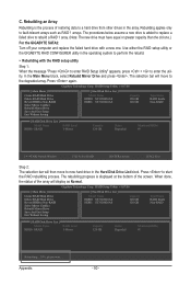
... replace a failed drive to rebuild a RAID 1 array. (Note: The new drive must have equal or greater capacity than the old one.) For the GIGABYTE SATA2: Turn off your computer and replace the failed hard drive with the RAID setup utility Step 1: When the message "Press to enter RAID Setup...the Hard Disk Drive List block. Appendix - 90 - Use either the RAID setup utility or the GIGABYTE RAID CONFIGURER utility in the operating system to the degraded array. RAID Setup Utility v1.07.06 [ Main Menu ] [ Hard Disk Drive List ] Create RAID Disk Drive Delete RAID Disk Drive Revert HDD to...
... replace a failed drive to rebuild a RAID 1 array. (Note: The new drive must have equal or greater capacity than the old one.) For the GIGABYTE SATA2: Turn off your computer and replace the failed hard drive with the RAID setup utility Step 1: When the message "Press to enter RAID Setup...the Hard Disk Drive List block. Appendix - 90 - Use either the RAID setup utility or the GIGABYTE RAID CONFIGURER utility in the operating system to the degraded array. RAID Setup Utility v1.07.06 [ Main Menu ] [ Hard Disk Drive List ] Create RAID Disk Drive Delete RAID Disk Drive Revert HDD to...
User Manual
Page 100
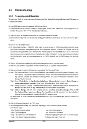
..., please go to the Support&Downloads\Motherboard\FAQ page on Microsoft UAA Bus Driver for High Definition Audio and select Disable and Uninstall. In the Main Menu, press + to clear the CMOS values (before doing this step.) Step 3: Then go back to My Computer > Properties > Hardware >... Device Manager > System devices and right-click on GIGABYTE's website. Q: Why do I still get a weak sound even though I install the onboard HD audio driver successfully? (For Windows XP only) A: Step 1:...
..., please go to the Support&Downloads\Motherboard\FAQ page on Microsoft UAA Bus Driver for High Definition Audio and select Disable and Uninstall. In the Main Menu, press + to clear the CMOS values (before doing this step.) Step 3: Then go back to My Computer > Properties > Hardware >... Device Manager > System devices and right-click on GIGABYTE's website. Q: Why do I still get a weak sound even though I install the onboard HD audio driver successfully? (For Windows XP only) A: Step 1:...