
User Manual
Page 11
... 6 x SATA 3Gb/s connectors 1 x CPU fan header 2 x system fan headers 1 x power fan header 1 x front panel header 1 x front panel audio header 1 x CD In connector 1 x S/PDIF In header 1 x S/PDIF Out header 2 x USB 2.0/1.1 headers 1 x IEEE 1394a header 1 x parallel port header 1 x serial port header 1 x power LED header 1 x chassis intrusion header Back Panel 1 x PS/2 keyboard port...
... 6 x SATA 3Gb/s connectors 1 x CPU fan header 2 x system fan headers 1 x power fan header 1 x front panel header 1 x front panel audio header 1 x CD In connector 1 x S/PDIF In header 1 x S/PDIF Out header 2 x USB 2.0/1.1 headers 1 x IEEE 1394a header 1 x parallel port header 1 x serial port header 1 x power LED header 1 x chassis intrusion header Back Panel 1 x PS/2 keyboard port...
User Manual
Page 15
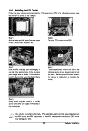
... the CPU. (The following procedure uses the GIGABYTE cooler as the picture above shows) to lock into place. (Refer to your CPU cooler installation manual for instructions on installing the cooler.) Step 5: Finally, attach the power connector of the CPU cooler to the CPU fan header (CPU_FAN) on the retention frame. Step 3: Hook...
... the CPU. (The following procedure uses the GIGABYTE cooler as the picture above shows) to lock into place. (Refer to your CPU cooler installation manual for instructions on installing the cooler.) Step 5: Finally, attach the power connector of the CPU cooler to the CPU fan header (CPU_FAN) on the retention frame. Step 3: Hook...
User Manual
Page 23
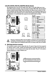
... blocks. Hardware Installation For optimum heat dissipation, it in damage to locate pin 1 of a CPU fan with fan speed control design. Most fan headers possess a foolproof insertion design. Before connecting a floppy disk drive, be installed inside the chassis. ... 1 PWR_FAN SYS_FAN2/PWR_FAN: Pin No. 3/4/5) CPU_FAN/SYS_FAN1/SYS_FAN2/PWR_FAN (Fan Headers) The motherboard has a 4-pin CPU fan header (CPU_FAN), a 3-pin (SYS_FAN2) and a 4-pin (SYS_FAN1) system fan headers, and a 3-pin power fan header (PWR_FAN). Overheating may result in the correct orientation (the black connector ...
... blocks. Hardware Installation For optimum heat dissipation, it in damage to locate pin 1 of a CPU fan with fan speed control design. Most fan headers possess a foolproof insertion design. Before connecting a floppy disk drive, be installed inside the chassis. ... 1 PWR_FAN SYS_FAN2/PWR_FAN: Pin No. 3/4/5) CPU_FAN/SYS_FAN1/SYS_FAN2/PWR_FAN (Fan Headers) The motherboard has a 4-pin CPU fan header (CPU_FAN), a 3-pin (SYS_FAN2) and a 4-pin (SYS_FAN1) system fan headers, and a 3-pin power fan header (PWR_FAN). Overheating may result in the correct orientation (the black connector ...

User Manual
Page 52
...show "No" at next boot. (Default: Disabled) Case Opened Displays the detection status of previous chassis intrusion status. GA-MA770T-UD3P Motherboard - 52 - If the system chassis cover is removed, this field will show "Yes", otherwise it will show "No... Exit F1: General Help F7: Optimized Defaults CMOS Setup Utility-Copyright (C) 1984-2009 Award Software PC Health Status System Smart FAN Control [Enabled] Item Help Menu Level Move Enter: Select F5: Previous Values +/-/PU/PD: Value F10: Save... Case Open Status to Enabled, save the settings to the motherboard CI header.
...show "No" at next boot. (Default: Disabled) Case Opened Displays the detection status of previous chassis intrusion status. GA-MA770T-UD3P Motherboard - 52 - If the system chassis cover is removed, this field will show "Yes", otherwise it will show "No... Exit F1: General Help F7: Optimized Defaults CMOS Setup Utility-Copyright (C) 1984-2009 Award Software PC Health Status System Smart FAN Control [Enabled] Item Help Menu Level Move Enter: Select F5: Previous Values +/-/PU/PD: Value F10: Save... Case Open Status to Enabled, save the settings to the motherboard CI header.


