User Manual
Page 3
...legally registered to their respective owners. Changes to use GIGABYTE's unique features, read or download the information on/from the Support\Motherboard\Technology Guide page on your motherboard revision before updating motherboard BIOS, drivers, or when looking for technical information. For ...product-related information, check on our website at: http://www.gigabyte.com Identifying Your Motherboard Revision The revision number on our website...
...legally registered to their respective owners. Changes to use GIGABYTE's unique features, read or download the information on/from the Support\Motherboard\Technology Guide page on your motherboard revision before updating motherboard BIOS, drivers, or when looking for technical information. For ...product-related information, check on our website at: http://www.gigabyte.com Identifying Your Motherboard Revision The revision number on our website...
User Manual
Page 4
Table of Contents Box Contents ...6 OptionalItems ...6 GA-MA770T-UD3P Motherboard Layout 7 Block Diagram ...8 Chapter 1 Hardware Installation 9 1-1 Installation Precautions 9 1-2 Product Specifications 10 1-3 Installing the CPU and CPU Cooler ... Installing an Expansion Card 18 1-6 Back Panel Connectors 19 1-7 Internal Connectors 21 Chapter 2 BIOS Setup 33 2-1 Startup Screen 34 2-2 The Main Menu 35 2-3 MB Intelligent Tweaker(M.I.T 37 2-4 Standard CMOS Features 42 2-5 Advanced BIOS Features 44 2-6 IntegratedPeripherals 46 2-7 Power Management Setup 50 2-8 PC Health Status 52 2-9 ...
Table of Contents Box Contents ...6 OptionalItems ...6 GA-MA770T-UD3P Motherboard Layout 7 Block Diagram ...8 Chapter 1 Hardware Installation 9 1-1 Installation Precautions 9 1-2 Product Specifications 10 1-3 Installing the CPU and CPU Cooler ... Installing an Expansion Card 18 1-6 Back Panel Connectors 19 1-7 Internal Connectors 21 Chapter 2 BIOS Setup 33 2-1 Startup Screen 34 2-2 The Main Menu 35 2-3 MB Intelligent Tweaker(M.I.T 37 2-4 Standard CMOS Features 42 2-5 Advanced BIOS Features 44 2-6 IntegratedPeripherals 46 2-7 Power Management Setup 50 2-8 PC Health Status 52 2-9 ...
User Manual
Page 5
... 58 3-3 Technical Manuals 58 3-4 Contact ...59 3-5 System ...59 3-6 Download Center 60 Chapter 4 Unique Features 61 4-1 Xpress Recovery2 61 4-2 BIOS Update Utilities 64 4-2-1 Updating the BIOS with the Q-Flash Utility 64 4-2-2 Updating the BIOS with the @BIOS Utility 67 4-3 EasyTune 6 ...68 4-4 Easy Energy Saver 69 4-5 Q-Share ...71 4-6 Time Repair ...72 Chapter 5 Appendix ...73 5-1 Configuring SATA...
... 58 3-3 Technical Manuals 58 3-4 Contact ...59 3-5 System ...59 3-6 Download Center 60 Chapter 4 Unique Features 61 4-1 Xpress Recovery2 61 4-2 BIOS Update Utilities 64 4-2-1 Updating the BIOS with the Q-Flash Utility 64 4-2-2 Updating the BIOS with the @BIOS Utility 67 4-3 EasyTune 6 ...68 4-4 Easy Energy Saver 69 4-5 Q-Share ...71 4-6 Time Repair ...72 Chapter 5 Appendix ...73 5-1 Configuring SATA...

User Manual
Page 8
Block Diagram PCIe CLK (100 MHz) 1 PCI Express x16 PCI Express x16 AM3 CPU CPU CLK+/-(200 MHz) DDR3 1666(O.C.)/1333/1066 MHz Dual Channel Memory Hyper Transport 3.0 PCI Express Bus x1 x1 x1 x1 AMD 770 PCIe CLK x1 (100 MHz) 4 PCI Express x1 RTL8111C/D(L) RJ45 LAN PCI Bus TSB43AB23 3 IEEE 1394a AMD SB710 CODEC ATA-133/100/66/33 IDE Channel 6 SATA 3Gb/s 12 USB Ports IT8720 Dual BIOS Floppy LPT Port COM Port PS/2 KB/Mouse Surround Speaker Out Center/Subwoofer Speaker Out Side Speaker Out MIC Line Out Line In S/PDIF In S/PDIF Out 2 PCI PCI CLK (33 MHz) - 8 -
Block Diagram PCIe CLK (100 MHz) 1 PCI Express x16 PCI Express x16 AM3 CPU CPU CLK+/-(200 MHz) DDR3 1666(O.C.)/1333/1066 MHz Dual Channel Memory Hyper Transport 3.0 PCI Express Bus x1 x1 x1 x1 AMD 770 PCIe CLK x1 (100 MHz) 4 PCI Express x1 RTL8111C/D(L) RJ45 LAN PCI Bus TSB43AB23 3 IEEE 1394a AMD SB710 CODEC ATA-133/100/66/33 IDE Channel 6 SATA 3Gb/s 12 USB Ports IT8720 Dual BIOS Floppy LPT Port COM Port PS/2 KB/Mouse Surround Speaker Out Center/Subwoofer Speaker Out Side Speaker Out MIC Line Out Line In S/PDIF In S/PDIF Out 2 PCI PCI CLK (33 MHz) - 8 -

User Manual
Page 11
... CPU/System/Power fan speed detection CPU overheating warning CPU/System/Power fan fail warning CPU/System fan speed control (Note 4) BIOS 2 x 8 Mbit flash Use of licensed AWARD BIOS Support for DualBIOSTM PnP 1.0a, DMI 2.0, SM...
... CPU/System/Power fan speed detection CPU overheating warning CPU/System/Power fan fail warning CPU/System fan speed control (Note 4) BIOS 2 x 8 Mbit flash Use of licensed AWARD BIOS Support for DualBIOSTM PnP 1.0a, DMI 2.0, SM...
User Manual
Page 12
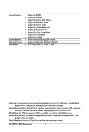
GA-MA770T-UD3P Motherboard - 12 - Unique Features Bundled Software Operating System Form Factor Support for @BIOS Support for Q-Flash Support for Xpress BIOS Rescue Support for Download Center Support for Xpress Install Support for Xpress Recovery2 Support for EasyTune (Note 5) Support for Easy ...
GA-MA770T-UD3P Motherboard - 12 - Unique Features Bundled Software Operating System Form Factor Support for @BIOS Support for Q-Flash Support for Xpress BIOS Rescue Support for Download Center Support for Xpress Install Support for Xpress Recovery2 Support for EasyTune (Note 5) Support for Easy ...
User Manual
Page 16
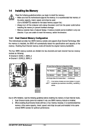
... sockets and supports Dual Channel Technology. Dual Channel mode cannot be used and installed in Dual Channel mode. 1. GA-MA770T-UD3P Motherboard - 16 - 1-4 Installing the Memory Read the following guidelines before installing the memory to prevent hardware damage. ... modules have a foolproof design. If you install them in only one DDR3 memory module is installed, the BIOS will double the original memory bandwidth. DS/SS DS/SS Four Modules DS/SS DS/SS DS/SS DS... only one direction. A memory module can be used . (Go to GIGABYTE's website for optimum performance.
... sockets and supports Dual Channel Technology. Dual Channel mode cannot be used and installed in Dual Channel mode. 1. GA-MA770T-UD3P Motherboard - 16 - 1-4 Installing the Memory Read the following guidelines before installing the memory to prevent hardware damage. ... modules have a foolproof design. If you install them in only one DDR3 memory module is installed, the BIOS will double the original memory bandwidth. DS/SS DS/SS Four Modules DS/SS DS/SS DS/SS DS... only one direction. A memory module can be used . (Go to GIGABYTE's website for optimum performance.
User Manual
Page 18
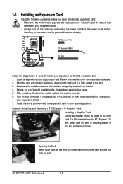
... Card Read the following guidelines before installing an expansion card to prevent hardware damage. GA-MA770T-UD3P Motherboard - 18 - Secure the card's metal bracket to make any required BIOS changes for your operating system. If necessary, go to BIOS Setup to the chassis back panel with the expansion card in the expansion slot. 1. Remove...
... Card Read the following guidelines before installing an expansion card to prevent hardware damage. GA-MA770T-UD3P Motherboard - 18 - Secure the card's metal bracket to make any required BIOS changes for your operating system. If necessary, go to BIOS Setup to the chassis back panel with the expansion card in the expansion slot. 1. Remove...
User Manual
Page 25
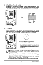
... Installation System Status LED S0 On S1 Blinking S3/S4/S5 Off 10) BAT (BATTERY) The battery provides power to keep the values (such as BIOS configurations, date, and time information) in the power cord and restart your computer. • Always turn off your computer and unplug the power cord before...
... Installation System Status LED S0 On S1 Blinking S3/S4/S5 Off 10) BAT (BATTERY) The battery provides power to keep the values (such as BIOS configurations, date, and time information) in the power cord and restart your computer. • Always turn off your computer and unplug the power cord before...

User Manual
Page 26
... front panel. A front panel module mainly consists of power switch, reset switch, power LED, hard drive activity LED, speaker and etc. GA-MA770T-UD3P Motherboard - 26 - RESRES+ NC Hard Drive Activity LED Reset Switch • MSG (Message/Power/Sleep LED, Yellow): System Status LED Connects ...Reset Switch, Green): Connects to the speaker on the chassis front panel. When connecting your system using the power switch (refer to Chapter 2, "BIOS Setup," "Power Management Setup," for information about beep codes. • HD (Hard Drive Activity LED, Blue) Connects to the hard drive activity...
... front panel. A front panel module mainly consists of power switch, reset switch, power LED, hard drive activity LED, speaker and etc. GA-MA770T-UD3P Motherboard - 26 - RESRES+ NC Hard Drive Activity LED Reset Switch • MSG (Message/Power/Sleep LED, Yellow): System Status LED Connects ...Reset Switch, Green): Connects to the speaker on the chassis front panel. When connecting your system using the power switch (refer to Chapter 2, "BIOS Setup," "Power Management Setup," for information about beep codes. • HD (Hard Drive Activity LED, Blue) Connects to the hard drive activity...

User Manual
Page 31
...on the two pins to temporarily short the two pins or use a metal object like a screwdriver to Chapter 2, "BIOS Setup," for a few seconds. date information and BIOS configurations) and reset the CMOS values to clear the CMOS values (e.g. Failure to do so may cause damage to ...the motherboard. • After system restart, go to BIOS Setup to load factory defaults (select Load Optimized Defaults) or manually configure the BIOS settings (refer to touch the two pins for BIOS configurations). - 31 - Hardware Installation 20) CI (Chassis Intrusion Header) This ...
...on the two pins to temporarily short the two pins or use a metal object like a screwdriver to Chapter 2, "BIOS Setup," for a few seconds. date information and BIOS configurations) and reset the CMOS values to clear the CMOS values (e.g. Failure to do so may cause damage to ...the motherboard. • After system restart, go to BIOS Setup to load factory defaults (select Load Optimized Defaults) or manually configure the BIOS settings (refer to touch the two pins for BIOS configurations). - 31 - Hardware Installation 20) CI (Chassis Intrusion Header) This ...
User Manual
Page 33
...the settings may result in the CMOS on the motherboard supplies the necessary power to the CMOS to Chapter 4, "BIOS Update Utilities." • Because BIOS flashing is potentially risky, if you do it is recommended that you not alter the default settings (unless you ... . To upgrade the BIOS, use either the GIGABYTE Q-Flash or @BIOS utility. • Q-Flash allows the user to activate certain system features. Inadequate BIOS flashing may result in system's failure to prevent system instability or other unexpected results. BIOS Setup BIOS includes a BIOS Setup program that allows ...
...the settings may result in the CMOS on the motherboard supplies the necessary power to the CMOS to Chapter 4, "BIOS Update Utilities." • Because BIOS flashing is potentially risky, if you do it is recommended that you not alter the default settings (unless you ... . To upgrade the BIOS, use either the GIGABYTE Q-Flash or @BIOS utility. • Q-Flash allows the user to activate certain system features. Inadequate BIOS flashing may result in system's failure to prevent system instability or other unexpected results. BIOS Setup BIOS includes a BIOS Setup program that allows ...

User Manual
Page 34
...directly without having to set the first boot device without entering BIOS Setup. After system restart, the device boot order will directly boot from the device configured in Boot Menu is effective for GA-MA770T-UD3P F1b . . . . : BIOS Setup : XpressRecovery2 : Boot Menu : Qflash 03/30/2009-... SCREEN Press the key to show the BIOS POST screen at system startup, refer to accept. The POST Screen Award Modular BIOS v6.00PG, An Energy Star Ally Copyright (C) 1984-2009, Award Software, Inc. To show the BIOS POST screen. GA-MA770T-UD3P Motherboard - 34 - 2-1 Startup Screen ...
...directly without having to set the first boot device without entering BIOS Setup. After system restart, the device boot order will directly boot from the device configured in Boot Menu is effective for GA-MA770T-UD3P F1b . . . . : BIOS Setup : XpressRecovery2 : Boot Menu : Qflash 03/30/2009-... SCREEN Press the key to show the BIOS POST screen at system startup, refer to accept. The POST Screen Award Modular BIOS v6.00PG, An Energy Star Ally Copyright (C) 1984-2009, Award Software, Inc. To show the BIOS POST screen. GA-MA770T-UD3P Motherboard - 34 - 2-1 Startup Screen ...
User Manual
Page 35
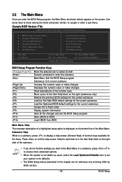
...Exit Without Saving ESC: Quit F8: Q-Flash Select Item F10: Save & Exit Setup F11: Save CMOS to BIOS F12: Load CMOS from BIOS Change CPU's Clock & Voltage BIOS Setup Program Function Keys Move the selection bar to select an item Execute command or enter the submenu Main Menu... for the current submenus Access the Q-Flash utility Display system information Save all the changes and exit the BIOS Setup program Save CMOS to BIOS Load CMOS from BIOS Main Menu Help The onscreen description of a highlighted setup option is displayed on the screen. Press to display...
...Exit Without Saving ESC: Quit F8: Q-Flash Select Item F10: Save & Exit Setup F11: Save CMOS to BIOS F12: Load CMOS from BIOS Change CPU's Clock & Voltage BIOS Setup Program Function Keys Move the selection bar to select an item Execute command or enter the submenu Main Menu... for the current submenus Access the Q-Flash utility Display system information Save all the changes and exit the BIOS Setup program Save CMOS to BIOS Load CMOS from BIOS Main Menu Help The onscreen description of a highlighted setup option is displayed on the screen. Press to display...
User Manual
Page 36
...profile. Pressing to 8 profiles (Profile 1-8) and name each profile. You can create up to the confirmation message will exit BIOS Setup. (Pressing can also carry out this task.) GA-MA770T-UD3P Motherboard - 36 - First select the profile you to make changes. Save & Exit Setup Save all the changes... made in the BIOS Setup program to the CMOS and exit BIOS Setup. (Pressing can also carry out this task.) &#...
...profile. Pressing to 8 profiles (Profile 1-8) and name each profile. You can create up to the confirmation message will exit BIOS Setup. (Pressing can also carry out this task.) GA-MA770T-UD3P Motherboard - 36 - First select the profile you to make changes. Save & Exit Setup Save all the changes... made in the BIOS Setup program to the CMOS and exit BIOS Setup. (Pressing can also carry out this task.) &#...
User Manual
Page 37
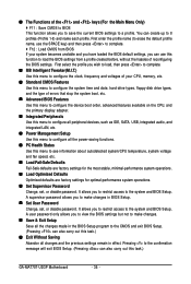
... to alter the default settings to prevent system instability or other unexpected results. (Inadequately alter ing the settings may result in system's failure to boot. BIOS Setup Incorrectly doing overclock/overvoltage may result in damage to optimize the system voltage settings. Advanced Clock Calibratioin CMOS Setup Utility-Copyright (C) 1984-2009 Award...
... to alter the default settings to prevent system instability or other unexpected results. (Inadequately alter ing the settings may result in system's failure to boot. BIOS Setup Incorrectly doing overclock/overvoltage may result in damage to optimize the system voltage settings. Advanced Clock Calibratioin CMOS Setup Utility-Copyright (C) 1984-2009 Award...
User Manual
Page 38
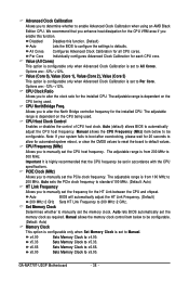
...only when Advanced Clock Calibration is set to Manual. CPU Frequency (MHz) Allows you enable this function. (Default) Auto Lets the BIOS to configure the settings to All Cores. The adjustable range is set to defaults. Per Core Individually configures Advanced Clock Calibration for each... configurable only when Set Memory Clock is from 100 MHz to default values. x6.66 Sets Memory Clock to x8.00. GA-MA770T-UD3P Motherboard - 38 - Disabled Disables this function. The adjustable range is highly recommended that you to alter the clock ratio for automated...
...only when Advanced Clock Calibration is set to Manual. CPU Frequency (MHz) Allows you enable this function. (Default) Auto Lets the BIOS to configure the settings to All Cores. The adjustable range is set to defaults. Per Core Individually configures Advanced Clock Calibration for each... configurable only when Set Memory Clock is from 100 MHz to default values. x6.66 Sets Memory Clock to x8.00. GA-MA770T-UD3P Motherboard - 38 - Disabled Disables this function. The adjustable range is highly recommended that you to alter the clock ratio for automated...

User Manual
Page 39
... be configurable. Sets memory control mode to two single-channel.(default) DDR3 Timing Items Manual allows all DDR3 Timing items below to single dual-channel. BIOS Setup DRAM Configuration CMOS Setup Utility-Copyright (C) 1984-2009 Award Software DRAM Configuration CPU Host Clock Control x CPU Frequency (MHz) Set Memory Clock x Memory Clock...
... be configurable. Sets memory control mode to two single-channel.(default) DDR3 Timing Items Manual allows all DDR3 Timing items below to single dual-channel. BIOS Setup DRAM Configuration CMOS Setup Utility-Copyright (C) 1984-2009 Award Software DRAM Configuration CPU Host Clock Control x CPU Frequency (MHz) Set Memory Clock x Memory Clock...

User Manual
Page 40
... Allows you to your CPU or reduce the useful life of the CPU. GA-MA770T-UD3P Motherboard - 40 - CAS# latency Options are : 90ns (default), 110ns, 160ns, 300ns, 350ns. Trfc0 for DIMM2 Options are : Auto (default), 5T~12T. Auto lets BIOS automatically set the system voltages. Trfc1 for DIMM4 Options are : 1T (default), 2T...
... Allows you to your CPU or reduce the useful life of the CPU. GA-MA770T-UD3P Motherboard - 40 - CAS# latency Options are : 90ns (default), 110ns, 160ns, 300ns, 350ns. Trfc0 for DIMM2 Options are : Auto (default), 5T~12T. Auto lets BIOS automatically set the system voltages. Trfc1 for DIMM4 Options are : 1T (default), 2T...
User Manual
Page 41
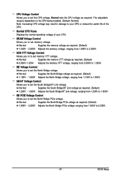
... VTT Voltage Control Allows you to set the South Bridge/HT Link voltage. SB/HT Voltage Control Allows you to to set memory VTT voltage. BIOS Setup NB PCIE Voltage Control Allows you to set memory voltage. DRAM Voltage Control Allows you to set the North Bridge PCIe voltage. NB Voltage...
... VTT Voltage Control Allows you to set the South Bridge/HT Link voltage. SB/HT Voltage Control Allows you to to set memory VTT voltage. BIOS Setup NB PCIE Voltage Control Allows you to set memory voltage. DRAM Voltage Control Allows you to set the North Bridge PCIe voltage. NB Voltage...


