Quick Start Guide
Page 2
... herein are trademarks or registered trademarks or their respective owners. Disclaimer Information in this manual is protected by copyright laws and is the property of GIGABYTE. Changes to the specifications and features in this manual may be made by GIGABYTE without GIGABYTE's prior written permission. or its affiliates. No part of GIGABYTE Technology Co., Ltd. BRIX Extreme Ultra Compact PC...
... herein are trademarks or registered trademarks or their respective owners. Disclaimer Information in this manual is protected by copyright laws and is the property of GIGABYTE. Changes to the specifications and features in this manual may be made by GIGABYTE without GIGABYTE's prior written permission. or its affiliates. No part of GIGABYTE Technology Co., Ltd. BRIX Extreme Ultra Compact PC...

Quick Start Guide
Page 10
CAUTION! Alerts you to different languages. Conventions The following conventions are used in this user's guide: NOTE! Languages This icon indicates the text is translated to any damage that might result from doing or not doing specific actions. Gives bits and pieces of additional information related to avoid possible hardware or software problems. WARNING! Gives precautionary measures to the current topic.
CAUTION! Alerts you to different languages. Conventions The following conventions are used in this user's guide: NOTE! Languages This icon indicates the text is translated to any damage that might result from doing or not doing specific actions. Gives bits and pieces of additional information related to avoid possible hardware or software problems. WARNING! Gives precautionary measures to the current topic.
Quick Start Guide
Page 13
... 22 2-3 Left View...23 2-3-1 Standard...23 2-3-2 HDD / Super...23 2-4 Right View...24 2-4-1 Standard...24 2-4-2 HDD / Super...24 2-5 Bottom View...25 2-6 PIN Definition 26 Chapter 3 System Hardware Installation 27 3-1 Removing the Bottom Cover 28 3-2 Installing the M.2 SSD 29 3-3 Installing the Memory 30 3-4 Remove the Wireless Module 31 3-5 Installing the VESA Bracket 32 3-6 Installing Additional SATA 6Gbps HDD (2.5" HDD 33 3-7 Installing LAN/COM/M.2 Upgrade Kit 35 Chapter 4 BIOS Setup 37 4-1 USB Power On Function 39 - 13 -
... 22 2-3 Left View...23 2-3-1 Standard...23 2-3-2 HDD / Super...23 2-4 Right View...24 2-4-1 Standard...24 2-4-2 HDD / Super...24 2-5 Bottom View...25 2-6 PIN Definition 26 Chapter 3 System Hardware Installation 27 3-1 Removing the Bottom Cover 28 3-2 Installing the M.2 SSD 29 3-3 Installing the Memory 30 3-4 Remove the Wireless Module 31 3-5 Installing the VESA Bracket 32 3-6 Installing Additional SATA 6Gbps HDD (2.5" HDD 33 3-7 Installing LAN/COM/M.2 Upgrade Kit 35 Chapter 4 BIOS Setup 37 4-1 USB Power On Function 39 - 13 -

Quick Start Guide
Page 14
...; Turning on the motherboard, make sure the power supply voltage has been set according to the local voltage standard. • Before using the product, please verify that all cables and power connectors of your hardware components are connected. • To prevent damage to the motherboard, do not remove or break motherboard S/N (Serial Number) sticker or warranty sticker provided by unplugging the power cord from the motherboard, make sure the power supply has...
...; Turning on the motherboard, make sure the power supply voltage has been set according to the local voltage standard. • Before using the product, please verify that all cables and power connectors of your hardware components are connected. • To prevent damage to the motherboard, do not remove or break motherboard S/N (Serial Number) sticker or warranty sticker provided by unplugging the power cord from the motherboard, make sure the power supply has...
Quick Start Guide
Page 15
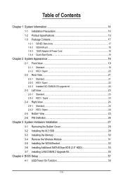
... GB-BEi5-1240 & GB-BEi5H-1240 & GB-BEi5HS-1240 12th Generation Intel® Core™ i5-1240P Processors, 12 Cores (4P+8E) 16 Threads, 12MB L2 Cache, Frequency 1.7GHz-4.4GHz(P Core), 28W GB-BEi3-1220 & GB-BEi3H-1220 12th Generation Intel® Core™ i3-1220P Processors, 10 Cores (2P+8E) 12 Threads, 12MB L2 Cache, Frequency 1.5GHz-4.4GHz(P Core), 28W Motherboard Size Memory LAN Video Wifi Card Audio...
... GB-BEi5-1240 & GB-BEi5H-1240 & GB-BEi5HS-1240 12th Generation Intel® Core™ i5-1240P Processors, 12 Cores (4P+8E) 16 Threads, 12MB L2 Cache, Frequency 1.7GHz-4.4GHz(P Core), 28W GB-BEi3-1220 & GB-BEi3H-1220 12th Generation Intel® Core™ i3-1220P Processors, 10 Cores (2P+8E) 12 Threads, 12MB L2 Cache, Frequency 1.5GHz-4.4GHz(P Core), 28W Motherboard Size Memory LAN Video Wifi Card Audio...

Quick Start Guide
Page 16
...; 1 x PCIe M.2 NGFF 2230 A-E key slot occupied by the WiFi+BT card Front I/O Rear I/O TPM Power Supply Support OS Environment Š 1 x Power Button Š 1 x USB 3.2 type C (Gen2) Š 3 x USB 3.2 type A (Gen2) Š 1 x head phone jack with MIC Š 2 x HDMI(2.1) Š 2 x HDMI(2.0b) Š 1 x mDP Š 1 x USB 4.0 (Support Intel Thunderbolt 4) w/ DP alt mode Š 2 x USB 3.2 type A (Gen 1) Š 1 x RJ45 Š 1 x DC-In Š 1 x Kensington lock slot Š Integrate TPM module* (in selected regions /countries...
...; 1 x PCIe M.2 NGFF 2230 A-E key slot occupied by the WiFi+BT card Front I/O Rear I/O TPM Power Supply Support OS Environment Š 1 x Power Button Š 1 x USB 3.2 type C (Gen2) Š 3 x USB 3.2 type A (Gen2) Š 1 x head phone jack with MIC Š 2 x HDMI(2.1) Š 2 x HDMI(2.0b) Š 1 x mDP Š 1 x USB 4.0 (Support Intel Thunderbolt 4) w/ DP alt mode Š 2 x USB 3.2 type A (Gen 1) Š 1 x RJ45 Š 1 x DC-In Š 1 x Kensington lock slot Š Integrate TPM module* (in selected regions /countries...
Quick Start Guide
Page 20
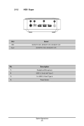
Power Button System Appearance - 20 - Description 1. Headphone/Microphone 2. USB 3.2 Gen2 with Type-C 3. 3 x USB 3.2 Gen2 Type A 4. 2-1-2 HDD / Super 12 3 4 SKU HDD Super Model GB-BEi7H-1260, GB-BEi5H-1240, GB-BEi3H-1220 GB-BEi7HS-1260, GB-BEi5HS-1240 No.
Power Button System Appearance - 20 - Description 1. Headphone/Microphone 2. USB 3.2 Gen2 with Type-C 3. 3 x USB 3.2 Gen2 Type A 4. 2-1-2 HDD / Super 12 3 4 SKU HDD Super Model GB-BEi7H-1260, GB-BEi5H-1240, GB-BEi3H-1220 GB-BEi7HS-1260, GB-BEi5HS-1240 No.
Quick Start Guide
Page 21
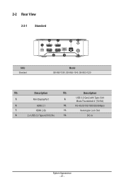
Mini DisplayPort 9. RJ-45(10/100/1000/2500Mbps) 7. DC-In System Appearance - 21 - USB 3.2 Gen2 with Type-CAlt Mode Thunderbolt 4 *(5V/3A) 6. HDMI 2.1 10. Kensington Lock Slot 8. 2 x USB 2.0 Type A(5V/0.5A) 12. Description 5. 2-2 Rear View 2-2-1 Standard SKU Standard 67 5 10 11 8 9 12 Model GB-BEi7-1260, GB-BEi5-1240, GB-BEi3-1220 No. HDMI 2.0b 11. Description No.
Mini DisplayPort 9. RJ-45(10/100/1000/2500Mbps) 7. DC-In System Appearance - 21 - USB 3.2 Gen2 with Type-CAlt Mode Thunderbolt 4 *(5V/3A) 6. HDMI 2.1 10. Kensington Lock Slot 8. 2 x USB 2.0 Type A(5V/0.5A) 12. Description 5. 2-2 Rear View 2-2-1 Standard SKU Standard 67 5 10 11 8 9 12 Model GB-BEi7-1260, GB-BEi5-1240, GB-BEi3-1220 No. HDMI 2.0b 11. Description No.
Quick Start Guide
Page 22
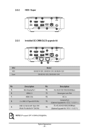
... 8 9 12 2-2-3 Installed GC-CMM-DLCS upgrade kit SKU HDD Super 6 5 7 10 11 9 8 12 13 14 Model GB-BEi7H-1260, GB-BEi5H-1240, GB-BEi3H-1220 GB-BEi7HS-1260, GB-BEi5HS-1240 No. Description 5. HDMI 2.1 11. RJ-45 (10/100/1000/2500Mbps) Mode Thunderbolt 4 *(5V/3A) (Optional Upgrade Kit NOTE! DP support DP1.4/3840x2160@60Hz System Appearance - 22 - Description No. USB 3.2 Gen2 with Type-CAlt 14. Console Port (Optional Upgrade Kit 9. DC-In 8. 2 x USB 2.0 Type A(5V...
... 8 9 12 2-2-3 Installed GC-CMM-DLCS upgrade kit SKU HDD Super 6 5 7 10 11 9 8 12 13 14 Model GB-BEi7H-1260, GB-BEi5H-1240, GB-BEi3H-1220 GB-BEi7HS-1260, GB-BEi5HS-1240 No. Description 5. HDMI 2.1 11. RJ-45 (10/100/1000/2500Mbps) Mode Thunderbolt 4 *(5V/3A) (Optional Upgrade Kit NOTE! DP support DP1.4/3840x2160@60Hz System Appearance - 22 - Description No. USB 3.2 Gen2 with Type-CAlt 14. Console Port (Optional Upgrade Kit 9. DC-In 8. 2 x USB 2.0 Type A(5V...
Quick Start Guide
Page 23
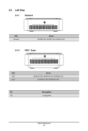
Model GB-BEi7H-1260, GB-BEi5H-1240, GB-BEi3H-1220 GB-BEi7HS-1260, GB-BEi5HS-1240 Description Cooling Vent System Appearance - 23 - 2-3 Left View 2-3-1 Standard 15 SKU Standard Model GB-BEi7-1260, GB-BEi5-1240, GB-BEi3-1220 2-3-2 HDD / Super 15 SKU HDD Super No. 15.
Model GB-BEi7H-1260, GB-BEi5H-1240, GB-BEi3H-1220 GB-BEi7HS-1260, GB-BEi5HS-1240 Description Cooling Vent System Appearance - 23 - 2-3 Left View 2-3-1 Standard 15 SKU Standard Model GB-BEi7-1260, GB-BEi5-1240, GB-BEi3-1220 2-3-2 HDD / Super 15 SKU HDD Super No. 15.

Quick Start Guide
Page 26
Wireless module inclusion may vary based on local distribution System Appearance - 26 - 2-6 PIN Definition B CD A PIN Definition A M.2 2280 SSD Connector B DDR SO-DIMM slot C Wi-Fi Connector D SATA connector for 2.5'' HDD or LAN/COM/M.2 Upgrade Kit ( *HDD/Super SKU ) NOTE!
Wireless module inclusion may vary based on local distribution System Appearance - 26 - 2-6 PIN Definition B CD A PIN Definition A M.2 2280 SSD Connector B DDR SO-DIMM slot C Wi-Fi Connector D SATA connector for 2.5'' HDD or LAN/COM/M.2 Upgrade Kit ( *HDD/Super SKU ) NOTE!

Quick Start Guide
Page 27
... are still connected to a power supply can be extremely dangerous. System Hardware Installation - 27 - Working on the board unless it is necessary to use the component for the installation. Do not flex or stress the circuit board. • Leave all components inside the static-proof packaging until you are working inside the computer case. Chapter 3 System Hardware Installation Pre-installation Instructions Computer components and electronic circuit boards can be...
... are still connected to a power supply can be extremely dangerous. System Hardware Installation - 27 - Working on the board unless it is necessary to use the component for the installation. Do not flex or stress the circuit board. • Leave all components inside the static-proof packaging until you are working inside the computer case. Chapter 3 System Hardware Installation Pre-installation Instructions Computer components and electronic circuit boards can be...

Quick Start Guide
Page 28
3-1 Removing the Bottom Cover Before you remove the bottom cover • Make sure the system is not turned on or connected to remove/install the Bottom Cover: 1. Slide the cover towards the rear of the system and then remove the cover in the direction indicated by the arrow. (取下M.2 SSD A 1 2 System Hardware Installation - 28 - Remove the screw securing the chassis side cover. (取下M.2 SSD A 2. Follow these instructions to AC power.
3-1 Removing the Bottom Cover Before you remove the bottom cover • Make sure the system is not turned on or connected to remove/install the Bottom Cover: 1. Slide the cover towards the rear of the system and then remove the cover in the direction indicated by the arrow. (取下M.2 SSD A 1 2 System Hardware Installation - 28 - Remove the screw securing the chassis side cover. (取下M.2 SSD A 2. Follow these instructions to AC power.

Quick Start Guide
Page 29
...instructions to the M.2 SSD slot A screw hole and the pre-installed thermal plate. (取下M.2 SSD A 2. Carefully insert the M.2 SSD into the slit near the connector, then secure the thermal plate and M.2 SSD in place with the previously removed screw M.2 SSD 2 1 3 System Hardware Installation - 29 - 3-2 Installing the M.2 SSD M.2 SSD: Installation der M.2 2280 SSD / SSD M.2 : Comment installer... plate into slot A M.2 SSD 裝入 A 插槽。) 3. Failure to properly turn off the system before you start installing components may cause serious damage.
...instructions to the M.2 SSD slot A screw hole and the pre-installed thermal plate. (取下M.2 SSD A 2. Carefully insert the M.2 SSD into the slit near the connector, then secure the thermal plate and M.2 SSD in place with the previously removed screw M.2 SSD 2 1 3 System Hardware Installation - 29 - 3-2 Installing the M.2 SSD M.2 SSD: Installation der M.2 2280 SSD / SSD M.2 : Comment installer... plate into slot A M.2 SSD 裝入 A 插槽。) 3. Failure to properly turn off the system before you start installing components may cause serious damage.

Quick Start Guide
Page 30
... Read the following guidelines before installing the memory to insert the memory, switch the direction. Push down until the modules click into place. 1 2 3 4 System Hardware Installation - 30 - SO-DIMM 2. A memory module can be used. • Always turn off the computer and unplug the power cord from the power outlet before you are unable to prevent hardware damage. • Memory modules have a foolproof design...
... Read the following guidelines before installing the memory to insert the memory, switch the direction. Push down until the modules click into place. 1 2 3 4 System Hardware Installation - 30 - SO-DIMM 2. A memory module can be used. • Always turn off the computer and unplug the power cord from the power outlet before you are unable to prevent hardware damage. • Memory modules have a foolproof design...

Quick Start Guide
Page 31
... the two antennas by manually lifting off the clips that hold them in the middle 3. Carefully pull the wireless module from the slot M.2 1 2 3 System Hardware Installation - 31 - Remove the screw in place 2. 3-4 Remove the Wireless Module Drahtlosmodul: Sicheres Entfernen...remover com segurança o modulo / Modulo senza cavi: Come rimuovere il modulo in sicurezza Moduł bezprzewodowy: Bezpieczne usuwanie modułu / Kablosuz Modül: Modül Güvenli Bir Şekilde nasıl Çıkartılır NOTE Follow these instructions to remove the WiFi...
... the two antennas by manually lifting off the clips that hold them in the middle 3. Carefully pull the wireless module from the slot M.2 1 2 3 System Hardware Installation - 31 - Remove the screw in place 2. 3-4 Remove the Wireless Module Drahtlosmodul: Sicheres Entfernen...remover com segurança o modulo / Modulo senza cavi: Come rimuovere il modulo in sicurezza Moduł bezprzewodowy: Bezpieczne usuwanie modułu / Kablosuz Modül: Modül Güvenli Bir Şekilde nasıl Çıkartılır NOTE Follow these instructions to remove the WiFi...

Quick Start Guide
Page 32
...; NOTE! Slide the first hard disk drive into the slot VESA VESA 3. Mount it with bottom side. Remove both side covers VESA BRIX Extreme 底部。) 2. Follow these instructions to install the VESA Bracket: 1. VESA screws: Length 5.0 mm with M3 type screws, metal enclosure with two screws on each side VESA BRIX Extreme 插入 VESA 1 2 3 System Hardware Installation - 32 -
...; NOTE! Slide the first hard disk drive into the slot VESA VESA 3. Mount it with bottom side. Remove both side covers VESA BRIX Extreme 底部。) 2. Follow these instructions to install the VESA Bracket: 1. VESA screws: Length 5.0 mm with M3 type screws, metal enclosure with two screws on each side VESA BRIX Extreme 插入 VESA 1 2 3 System Hardware Installation - 32 -
Quick Start Guide
Page 33
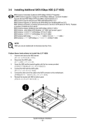
... these instructions to the SATA connector on the motherboard SATA 接頭) 6. Connect the other end of the cable to install the 2.5" HDD: 1. Reinstall the bracket with its thickness less than 7mm. HDD can only be installed with HDD to bottom panel. (將裝有HDD 1 System Hardware Installation - 33 - Disconnect the SATA cable SATA 線) 3. Screw the HDD and the bracket together with the SATA cable. (將 SATA Cable 與 HDD 相連) 5. Connect the HDD...
... these instructions to the SATA connector on the motherboard SATA 接頭) 6. Connect the other end of the cable to install the 2.5" HDD: 1. Reinstall the bracket with its thickness less than 7mm. HDD can only be installed with HDD to bottom panel. (將裝有HDD 1 System Hardware Installation - 33 - Disconnect the SATA cable SATA 線) 3. Screw the HDD and the bracket together with the SATA cable. (將 SATA Cable 與 HDD 相連) 5. Connect the HDD...

Quick Start Guide
Page 35
... with a thermal plate due to the space limitation. This system does not support the installation of the cable to bottom panel 1 System Hardware Installation - 35 - Connect the other end of both LAN/COM kit and 2.5" HDD; also the M.2 module here cannot be equipped with upgrade kit to the SATA connector on the motherboard SATA 接頭) 6. Follow these instructions to the upgrade kit board 5. 3-7 Installing LAN/COM/M.2 Upgrade Kit NOTE!
... with a thermal plate due to the space limitation. This system does not support the installation of the cable to bottom panel 1 System Hardware Installation - 35 - Connect the other end of both LAN/COM kit and 2.5" HDD; also the M.2 module here cannot be equipped with upgrade kit to the SATA connector on the motherboard SATA 接頭) 6. Follow these instructions to the upgrade kit board 5. 3-7 Installing LAN/COM/M.2 Upgrade Kit NOTE!

Quick Start Guide
Page 37
... 'USB Power-On Patch'. Your GIGABYTE BRIX can be powered on via a connected USB device such as a keyboard or mouse, offering greater convenience when mounted behind a display or monitor. Manually configure "USB S5 Wakeup Support" settings to Save and Exit. (按啟 F4 BIOS BIOS Setup - 37 - Windows USB Power-On USB Power-On Patch USB PowerOn BRIX 上的 USB BRIX BRIX Follow these instructions to enter BIOS Del 鍵進入 BIOS 2. Press "Del" during device start up to enable USB Power On: 1. Useful...
... 'USB Power-On Patch'. Your GIGABYTE BRIX can be powered on via a connected USB device such as a keyboard or mouse, offering greater convenience when mounted behind a display or monitor. Manually configure "USB S5 Wakeup Support" settings to Save and Exit. (按啟 F4 BIOS BIOS Setup - 37 - Windows USB Power-On USB Power-On Patch USB PowerOn BRIX 上的 USB BRIX BRIX Follow these instructions to enter BIOS Del 鍵進入 BIOS 2. Press "Del" during device start up to enable USB Power On: 1. Useful...
