User Manual
Page 13
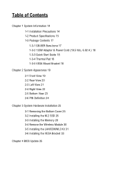
... Adapter & Power Cord (19.5 Vdc, 6.92 A ) 18 1-3-3 Quick Start Guide 18 1-3-4 Thermal Pad 18 1-3-5 VESA Mount Bracket 18 Chapter 2 System Appearance 19 2-1 Front View 19 2-2 Rear View 20 2-3 Left View 21 2-4 Right View 22 2-5 Bottom View 23 2-6 PIN Definition 24 Chapter 3 System Hardware Installation 25 3-1 Removing the Bottom Cover 25 3-2 Installing the M.2 SSD 26 3-3 Installing the Memory 28 3-4 Remove the Wireless Module 30 3-5 Installing the LAN/COM...
... Adapter & Power Cord (19.5 Vdc, 6.92 A ) 18 1-3-3 Quick Start Guide 18 1-3-4 Thermal Pad 18 1-3-5 VESA Mount Bracket 18 Chapter 2 System Appearance 19 2-1 Front View 19 2-2 Rear View 20 2-3 Left View 21 2-4 Right View 22 2-5 Bottom View 23 2-6 PIN Definition 24 Chapter 3 System Hardware Installation 25 3-1 Removing the Bottom Cover 25 3-2 Installing the M.2 SSD 26 3-3 Installing the Memory 28 3-4 Remove the Wireless Module 30 3-5 Installing the LAN/COM...
User Manual
Page 14
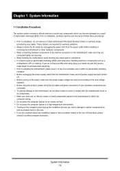
... using the product, please verify that all cables and power connectors of an antistatic pad or within the computer casing. Always remove the AC power by your dealer. Do not place the computer system on the motherboard, make sure the power supply has been turned off. Prior to installation, carefully read the user manual and follow these procedures: Prior to the user. These stickers are connected. Turning on...
... using the product, please verify that all cables and power connectors of an antistatic pad or within the computer casing. Always remove the AC power by your dealer. Do not place the computer system on the motherboard, make sure the power supply has been turned off. Prior to installation, carefully read the user manual and follow these procedures: Prior to the user. These stickers are connected. Turning on...
User Manual
Page 15
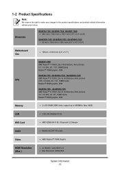
... Radeon™ 660M graphic, 28W Memory 2 x SO-DIMM DDR5 slots, support up to the product specifications and product-related information without prior notice. 1-2 Product Specifications Note: We reserve the right to make any changes to 5600MHz, Max. 64GB LAN 2.5G LAN (Realtek 8125) WiFi Card AMD RZ608 Wi-Fi 6E / Bluetooth 5.2 Module Audio Realtek ALC897 HD audio Video AMD Radeon™ 780M Graphic HDMI Resolution (Max.) 2x...
... Radeon™ 660M graphic, 28W Memory 2 x SO-DIMM DDR5 slots, support up to the product specifications and product-related information without prior notice. 1-2 Product Specifications Note: We reserve the right to make any changes to 5600MHz, Max. 64GB LAN 2.5G LAN (Realtek 8125) WiFi Card AMD RZ608 Wi-Fi 6E / Bluetooth 5.2 Module Audio Realtek ALC897 HD audio Video AMD Radeon™ 780M Graphic HDMI Resolution (Max.) 2x...
User Manual
Page 16
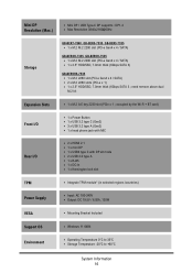
...dual M.2 kit Expansion Slots 1 x M.2 A-E key 2230 slot (PCIe x 1 ; Mini DP Resolution (Max.) Mini DP / USB Type-C DP supports : DP1.4 Max Resolution 3840x2160@60Hz Storage GB-BER7-7840, GB-BER5-7535, GB-BER3-7335 1 x M.2 M.2 2280 slot (PCI-e Gen4 x 4 / SATA) GB-BER3H-7335, GB-BER5H-7535 1 x M.2 M.2 2280 slot (PCI-e Gen4 x 4 / SATA) 1 x 2.5" HDD/SSD, 7.0mm thick (6Gbps SATA 3) GB-BER5HS-7535 1 x M.2 2280 slot (PCI-e Gen4 x 4 / SATA) 2 x M.2 2280 slots (PCI-e x 1) 1 x 2.5" HDD/SSD, 7.0mm thick (6Gbps SATA 3 ; occupied by the Wi-Fi + BT card) Front I/O 1 x Power Button 1 x USB 3.2 type...
...dual M.2 kit Expansion Slots 1 x M.2 A-E key 2230 slot (PCIe x 1 ; Mini DP Resolution (Max.) Mini DP / USB Type-C DP supports : DP1.4 Max Resolution 3840x2160@60Hz Storage GB-BER7-7840, GB-BER5-7535, GB-BER3-7335 1 x M.2 M.2 2280 slot (PCI-e Gen4 x 4 / SATA) GB-BER3H-7335, GB-BER5H-7535 1 x M.2 M.2 2280 slot (PCI-e Gen4 x 4 / SATA) 1 x 2.5" HDD/SSD, 7.0mm thick (6Gbps SATA 3) GB-BER5HS-7535 1 x M.2 2280 slot (PCI-e Gen4 x 4 / SATA) 2 x M.2 2280 slots (PCI-e x 1) 1 x 2.5" HDD/SSD, 7.0mm thick (6Gbps SATA 3 ; occupied by the Wi-Fi + BT card) Front I/O 1 x Power Button 1 x USB 3.2 type...
User Manual
Page 20
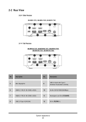
Description 5 Mini DisplayPort 6 HDMI 2.1 FRL10 8K (7680 x 4320) 7 HDMI 2.1 FRL10 8K (7680 x 4320) 8 USB 2.0 Type A (5V/0.5A) No. Description USB 3.2 Gen2 with Type C 9 Alt Mode Thunderbolt 4 (5V/3A) 10 RJ-45 (10/100/1000/2500Mbps) 11 Kensington Lock Slot ( ) 12 DC-In System Appearance 20 2C-2haRpetoarr 2VieSwystem Appearance 2-2-1 Slim Version GB-BER3-7375, GB-BER5-7535, GB-BER7-7740 2-1-1 Tall Version GB-BER3H-7375, GB-BER3HS-7375, GB-BER5H-7535, GB-BER5HS-7535, GB-BER7HS-7840 No.
Description 5 Mini DisplayPort 6 HDMI 2.1 FRL10 8K (7680 x 4320) 7 HDMI 2.1 FRL10 8K (7680 x 4320) 8 USB 2.0 Type A (5V/0.5A) No. Description USB 3.2 Gen2 with Type C 9 Alt Mode Thunderbolt 4 (5V/3A) 10 RJ-45 (10/100/1000/2500Mbps) 11 Kensington Lock Slot ( ) 12 DC-In System Appearance 20 2C-2haRpetoarr 2VieSwystem Appearance 2-2-1 Slim Version GB-BER3-7375, GB-BER5-7535, GB-BER7-7740 2-1-1 Tall Version GB-BER3H-7375, GB-BER3HS-7375, GB-BER5H-7535, GB-BER5HS-7535, GB-BER7HS-7840 No.
User Manual
Page 21
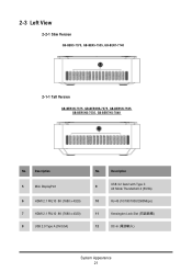
Description 5 Mini DisplayPort 6 HDMI 2.1 FRL10 8K (7680 x 4320) 7 HDMI 2.1 FRL10 8K (7680 x 4320) 8 USB 2.0 Type A (5V/0.5A) No. 2C-3haLpetoftrV2ieSwystem Appearance 2-2-1 Slim Version GB-BER3-7375, GB-BER5-7535, GB-BER7-7740 2-1-1 Tall Version GB-BER3H-7375, GB-BER3HS-7375, GB-BER5H-7535, GB-BER5HS-7535, GB-BER7HS-7840 No. Description USB 3.2 Gen2 with Type C 9 Alt Mode Thunderbolt 4 (5V/3A) 10 RJ-45 (10/100/1000/2500Mbps) 11 Kensington Lock Slot ( ) 12 DC-In System Appearance 21
Description 5 Mini DisplayPort 6 HDMI 2.1 FRL10 8K (7680 x 4320) 7 HDMI 2.1 FRL10 8K (7680 x 4320) 8 USB 2.0 Type A (5V/0.5A) No. 2C-3haLpetoftrV2ieSwystem Appearance 2-2-1 Slim Version GB-BER3-7375, GB-BER5-7535, GB-BER7-7740 2-1-1 Tall Version GB-BER3H-7375, GB-BER3HS-7375, GB-BER5H-7535, GB-BER5HS-7535, GB-BER7HS-7840 No. Description USB 3.2 Gen2 with Type C 9 Alt Mode Thunderbolt 4 (5V/3A) 10 RJ-45 (10/100/1000/2500Mbps) 11 Kensington Lock Slot ( ) 12 DC-In System Appearance 21
User Manual
Page 22
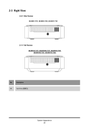
2C-3haRpitgohr t2ViSeywstem Appearance 2-2-1 Slim Version GB-BER3-7375, GB-BER5-7535, GB-BER7-7740 2-1-1 Tall Version GB-BER3H-7375, GB-BER3HS-7375, GB-BER5H-7535, GB-BER5HS-7535, GB-BER7HS-7840 No. Description 13 通風孔 Vent Hole ( ) System Appearance 22
2C-3haRpitgohr t2ViSeywstem Appearance 2-2-1 Slim Version GB-BER3-7375, GB-BER5-7535, GB-BER7-7740 2-1-1 Tall Version GB-BER3H-7375, GB-BER3HS-7375, GB-BER5H-7535, GB-BER5HS-7535, GB-BER7HS-7840 No. Description 13 通風孔 Vent Hole ( ) System Appearance 22

User Manual
Page 25
... touch the components on computers that are working inside the computer case. If possible, wear a grounded wrist strap when you are still connected to remove/install the Bottom Cover: Unscrew and remove the bottom cover from the power outlet whenever you are ready to use the component for the installation. 3-1 Removing the Bottom Cover Before you remove the bottom cover Make sure the system is necessary to...
... touch the components on computers that are working inside the computer case. If possible, wear a grounded wrist strap when you are still connected to remove/install the Bottom Cover: Unscrew and remove the bottom cover from the power outlet whenever you are ready to use the component for the installation. 3-1 Removing the Bottom Cover Before you remove the bottom cover Make sure the system is necessary to...

User Manual
Page 26
M.2 SSD System Hardware Installation 26 Follow these instructions to Install the M.2 SSD: Remove both the small screw secured to properly turn off the system before you start installing components may cause serious damage. Failure to the M.2 SSD screw hole. Reinstall the bottom cover to system. 3-2 Installing the M.2 SSD M.2 SSD: Installation der M.2 2280 SSD / SSD M.2 : Comment installer le SSD M.2 2280 / SSD M.2: Como instalar el SSD...
M.2 SSD System Hardware Installation 26 Follow these instructions to Install the M.2 SSD: Remove both the small screw secured to properly turn off the system before you start installing components may cause serious damage. Failure to the M.2 SSD screw hole. Reinstall the bottom cover to system. 3-2 Installing the M.2 SSD M.2 SSD: Installation der M.2 2280 SSD / SSD M.2 : Comment installer le SSD M.2 2280 / SSD M.2: Como instalar el SSD...

User Manual
Page 28
.... Follow these instructions to install the memory: Make sure that memory of the same capacity, brand, speed, and chips be installed in only one direction. If you begin to Install the Memory (SO-DIMM DDR4): Carefully insert SO-DIMM memory modules. SO-DIMM 點。 Push down until the modules click into place System Hardware Installation 28 A memory module can be used. Memory modules have...
.... Follow these instructions to install the memory: Make sure that memory of the same capacity, brand, speed, and chips be installed in only one direction. If you begin to Install the Memory (SO-DIMM DDR4): Carefully insert SO-DIMM memory modules. SO-DIMM 點。 Push down until the modules click into place System Hardware Installation 28 A memory module can be used. Memory modules have...
User Manual
Page 30
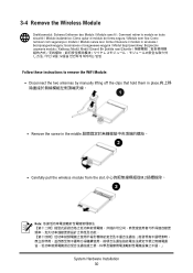
...o te System Hardware Installation 30 3-4 Remove the Wireless Module Drahtlosmodul: Sicheres Entfernen des Moduls / Module sans fil : Comment retirer le module en toute sécurité / Módulo inalámbrico: Cómo quitar el módulo de forma segura / Módulo sem fios: Como remover com seguranç...;l: Modül Güvenli Bir Şekilde nasıl Çıkartılır / / : Follow these instructions to remove the WiFi Module: Disconnect the two antennas by manually lifting off the clips that hold them in the middle Carefully pull the...
...o te System Hardware Installation 30 3-4 Remove the Wireless Module Drahtlosmodul: Sicheres Entfernen des Moduls / Module sans fil : Comment retirer le module en toute sécurité / Módulo inalámbrico: Cómo quitar el módulo de forma segura / Módulo sem fios: Como remover com seguranç...;l: Modül Güvenli Bir Şekilde nasıl Çıkartılır / / : Follow these instructions to remove the WiFi Module: Disconnect the two antennas by manually lifting off the clips that hold them in the middle Carefully pull the...

User Manual
Page 31
... the upgrade kit board. Follow these instructions to remove the WiFi Module: Unscrew and remove the bracket, and then disconnect the SATA cable SATA Install the upgrade kit board onto the bottom panel using the four screws provided, then connect the cable included in the upgrade kit to the space limitation. 3-5 Installing the LAN/COM/M.2 Kit This system does not support the installation of the cable to the SATA connector on the motherboard SATA System Hardware Installation 31...
... the upgrade kit board. Follow these instructions to remove the WiFi Module: Unscrew and remove the bracket, and then disconnect the SATA cable SATA Install the upgrade kit board onto the bottom panel using the four screws provided, then connect the cable included in the upgrade kit to the space limitation. 3-5 Installing the LAN/COM/M.2 Kit This system does not support the installation of the cable to the SATA connector on the motherboard SATA System Hardware Installation 31...
User Manual
Page 33
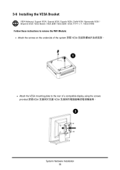
3-6 Installing the VESA Bracket VESA Halterung / Support VESA / Soporte VESA / Suporte VESA / Staffa VESA VESA / Wspornik VESA / VESA Braketi / VESA / VESA / VESA / VESA Follow these instructions to the rear of the system. VESA VESA System Hardware Installation 33 VESA Attach the VESA mounting plate to remove the WiFi Module: Attach the screws on the underside of a compatible display using the screws provided.
3-6 Installing the VESA Bracket VESA Halterung / Support VESA / Soporte VESA / Suporte VESA / Staffa VESA VESA / Wspornik VESA / VESA Braketi / VESA / VESA / VESA / VESA Follow these instructions to the rear of the system. VESA VESA System Hardware Installation 33 VESA Attach the VESA mounting plate to remove the WiFi Module: Attach the screws on the underside of a compatible display using the screws provided.
User Manual
Page 35
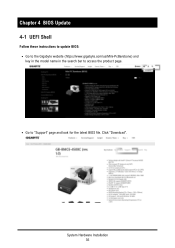
Go to access the product page. System Hardware Installation 35 Chaptor 4 BIOS Update 4-1 UEFI Shell Follow these instructions to update BIOS: Go to the Gigabyte website (https://www.gigabyte.com/us/Mini-PcBarebone) and key in the model name in the search bar to "Support" page and look for the latest BIOS file. Click "Download".
Go to access the product page. System Hardware Installation 35 Chaptor 4 BIOS Update 4-1 UEFI Shell Follow these instructions to update BIOS: Go to the Gigabyte website (https://www.gigabyte.com/us/Mini-PcBarebone) and key in the model name in the search bar to "Support" page and look for the latest BIOS file. Click "Download".
User Manual
Page 36
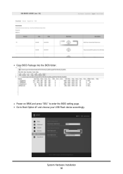
Power on BRIX and press "DEL" to Boot Option #1 and choose your USB Flash device accordingly. System Hardware Installation 36 Go to enter the BIOS setting page. Copy BIOS Package into the BIOS folder.
Power on BRIX and press "DEL" to Boot Option #1 and choose your USB Flash device accordingly. System Hardware Installation 36 Go to enter the BIOS setting page. Copy BIOS Package into the BIOS folder.

User Manual
Page 37
Click "Save Changes and Reset" to select your USB drive. System Hardware Installation 37 All the devices will be displayed on the screen, then type "fs0" to save configuration and exit, then select "Yes".
Click "Save Changes and Reset" to select your USB drive. System Hardware Installation 37 All the devices will be displayed on the screen, then type "fs0" to save configuration and exit, then select "Yes".

User Manual
Page 38
Enter the BIOS folder and type "flash.nsh" to start the BIOS update process. After a few minutes, you will see the following screen during the update. System Hardware Installation 38
Enter the BIOS folder and type "flash.nsh" to start the BIOS update process. After a few minutes, you will see the following screen during the update. System Hardware Installation 38
Quick Start Guide
Page 1
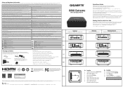
...;т. 10 10 Failure to use the included Model GB-BER Power Adapter may violate regulatory compliance and may not cause harmful interference, and (2) this product should not be used with Type C Alt Mode Thunderbolt 4 (5V/3A) Falls das mitgelieferte Netzteil Modell GB-BER nicht verwendet wird... 0℃~35 0℃~35 HDD Version GB-BER3H-7335, GB-BER5H-7535 Expansion Card Version GB-BER3HS-7335, GB-BER5HS-7535, GB-BER7HS-7840 12 3 4 67 5 10 11 8 9 12 13 13 R3F465 RoHS At the end of their respec�ve owners. Keep batteries out of reach of electrical...
...;т. 10 10 Failure to use the included Model GB-BER Power Adapter may violate regulatory compliance and may not cause harmful interference, and (2) this product should not be used with Type C Alt Mode Thunderbolt 4 (5V/3A) Falls das mitgelieferte Netzteil Modell GB-BER nicht verwendet wird... 0℃~35 0℃~35 HDD Version GB-BER3H-7335, GB-BER5H-7535 Expansion Card Version GB-BER3HS-7335, GB-BER5HS-7535, GB-BER7HS-7840 12 3 4 67 5 10 11 8 9 12 13 13 R3F465 RoHS At the end of their respec�ve owners. Keep batteries out of reach of electrical...
Quick Start Guide
Page 2
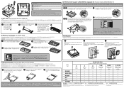
... 5.0 mm with M3 type screws, Metal enclosure with upgrade kit to bo�om panel the upgrade kit board 4 3 NOTE: Please ensure a thermal pad is a�ached on the motherboard. Installing a SO-DIMM device without any thermal pad may result in place with the previously removed screw M.2 SSD 3 4 Install the upgrade kit board onto the bo�om panel using the screws provided VESA...
... 5.0 mm with M3 type screws, Metal enclosure with upgrade kit to bo�om panel the upgrade kit board 4 3 NOTE: Please ensure a thermal pad is a�ached on the motherboard. Installing a SO-DIMM device without any thermal pad may result in place with the previously removed screw M.2 SSD 3 4 Install the upgrade kit board onto the bo�om panel using the screws provided VESA...
datasheet
Page 1
...-Fi + BT card) Front I/O Rear I/O TPM Power Supply VESA Support OS 1 x Power Button 1 x USB 3.2 type C (Gen2) 3 x USB 3.2 type A (Gen2) 1 x head phone jack with MIC 2 x HDMI (2.1) 1 x mini DP 1 x USB4 type C with HDCP 2.3 Resolution (Max.) Max Resolution 3840x2160@60Hz Mini DP Resolution (Max.) Mini DP / USB Type-C DP supports : DP1.4 Max Resolution 3840x2160@60Hz Storage 1 x M.2 M.2 2280 slot (PCI-e Gen4 x 4 / SATA) 1 x 2.5" HDD/SSD, 7.0mm thick (6Gbps SATA 3) 1 x M.2 A-E key 2230 slot (PCIe x 1 ; GB-BER3H-7335 / GB-BER5H-7535 BRIX Extreme / Ultra...
...-Fi + BT card) Front I/O Rear I/O TPM Power Supply VESA Support OS 1 x Power Button 1 x USB 3.2 type C (Gen2) 3 x USB 3.2 type A (Gen2) 1 x head phone jack with MIC 2 x HDMI (2.1) 1 x mini DP 1 x USB4 type C with HDCP 2.3 Resolution (Max.) Max Resolution 3840x2160@60Hz Mini DP Resolution (Max.) Mini DP / USB Type-C DP supports : DP1.4 Max Resolution 3840x2160@60Hz Storage 1 x M.2 M.2 2280 slot (PCI-e Gen4 x 4 / SATA) 1 x 2.5" HDD/SSD, 7.0mm thick (6Gbps SATA 3) 1 x M.2 A-E key 2230 slot (PCIe x 1 ; GB-BER3H-7335 / GB-BER5H-7535 BRIX Extreme / Ultra...
