
Manual
Page 3
... and features in this manual may be made by GIGABYTE without GIGABYTE's prior written permission. For product-related information, check on our website at: http://www.gigabyte.com Identifying Your Motherboard Revision The revision number on your motherboard revision before updating motherboard BIOS, drivers, or when looking for technical information. Check... order to their respective owners. The trademarks mentioned in the use of this manual are legally registered to assist in this product, GIGABYTE provides the following types of documentations: „„ For quick set-up of...
... and features in this manual may be made by GIGABYTE without GIGABYTE's prior written permission. For product-related information, check on our website at: http://www.gigabyte.com Identifying Your Motherboard Revision The revision number on your motherboard revision before updating motherboard BIOS, drivers, or when looking for technical information. Check... order to their respective owners. The trademarks mentioned in the use of this manual are legally registered to assist in this product, GIGABYTE provides the following types of documentations: „„ For quick set-up of...
Manual
Page 4
Table of Contents Box Contents...6 Optional Items...6 GA-Z77X-UP7 Motherboard Layout 7 GA-Z77X-UP7 Motherboard Block Diagram 8 Chapter 1 Hardware Installation 9 1-1 Installation Precautions 9 1-2 Product Specifications 10 1-3 Installing the CPU and CPU Cooler 13...20 1-8 Back Panel Connectors 21 1-9 Onboard Buttons, Switches and LEDs 24 1-10 Internal Connectors 27 Chapter 2 BIOS Setup 37 2-1 Startup Screen 38 2-2 The Main Menu 39 2-3 M.I.T...41 2-4 System...53 2-5 BIOS Features 54 2-6 Peripherals...57 2-7 Power Management 62 2-8 Save & Exit...64 Chapter 3 Drivers Installation 65 ...
Table of Contents Box Contents...6 Optional Items...6 GA-Z77X-UP7 Motherboard Layout 7 GA-Z77X-UP7 Motherboard Block Diagram 8 Chapter 1 Hardware Installation 9 1-1 Installation Precautions 9 1-2 Product Specifications 10 1-3 Installing the CPU and CPU Cooler 13...20 1-8 Back Panel Connectors 21 1-9 Onboard Buttons, Switches and LEDs 24 1-10 Internal Connectors 27 Chapter 2 BIOS Setup 37 2-1 Startup Screen 38 2-2 The Main Menu 39 2-3 M.I.T...41 2-4 System...53 2-5 BIOS Features 54 2-6 Peripherals...57 2-7 Power Management 62 2-8 Save & Exit...64 Chapter 3 Drivers Installation 65 ...

Manual
Page 5
3-6 Download Center 68 3-7 New Program 68 Chapter 4 Unique Features 69 4-1 Xpress Recovery2 69 4-2 BIOS Update Utilities 72 4-2-1 Updating the BIOS with the Q-Flash Utility 72 4-2-2 Updating the BIOS with the @BIOS Utility 75 4-3 EasyTune 6...76 4-4 Q-Share...77 4-5 eXtreme Hard Drive (X.H.D 78 4-6 Auto Green...79 4-7 EZ Setup...80 4-7-1 Installing EZ Smart Response 81 4-7-2 Installing EZ Rapid...
3-6 Download Center 68 3-7 New Program 68 Chapter 4 Unique Features 69 4-1 Xpress Recovery2 69 4-2 BIOS Update Utilities 72 4-2-1 Updating the BIOS with the Q-Flash Utility 72 4-2-2 Updating the BIOS with the @BIOS Utility 75 4-3 EasyTune 6...76 4-4 Q-Share...77 4-5 eXtreme Hard Drive (X.H.D 78 4-6 Auto Green...79 4-7 EZ Setup...80 4-7-1 Installing EZ Smart Response 81 4-7-2 Installing EZ Rapid...
Manual
Page 8
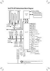
GA-Z77X-UP7 Motherboard Block Diagram 2 PCI Express x8 2 PCI Express x8 LGA1155 CPU CPU CLK+/- (100 MHz) DDR3 1600/1333/1066 MHz Dual Channel Memory 1 PCI Express ... Intel® Z77 Switch DisplayPort HDMI DVI-D D-Sub 2 SATA 6Gb/s 3 SATA 3Gb/s 1 SATA 3Gb/s or 1 mSATA 4 USB 3.0/2.0 VIA VL800 Etron EJ168 2 USB 3.0/2.0 4 USB 2.0/1.1 4 USB 3.0/2.0 Dual BIOS LPC Bus iTE COM Super I/O PS/2 KB/Mouse Rear Speaker Out Center/Subwoofer Speaker Out Side Speaker Out MIC Line Out Line In S/PDIF Out...
GA-Z77X-UP7 Motherboard Block Diagram 2 PCI Express x8 2 PCI Express x8 LGA1155 CPU CPU CLK+/- (100 MHz) DDR3 1600/1333/1066 MHz Dual Channel Memory 1 PCI Express ... Intel® Z77 Switch DisplayPort HDMI DVI-D D-Sub 2 SATA 6Gb/s 3 SATA 3Gb/s 1 SATA 3Gb/s or 1 mSATA 4 USB 3.0/2.0 VIA VL800 Etron EJ168 2 USB 3.0/2.0 4 USB 2.0/1.1 4 USB 3.0/2.0 Dual BIOS LPC Bus iTE COM Super I/O PS/2 KB/Mouse Rear Speaker Out Center/Subwoofer Speaker Out Side Speaker Out MIC Line Out Line In S/PDIF Out...

Manual
Page 12
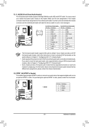
... Support for EasyTune * Available functions in EasyTune may differ by motherboard model. Hardware Installation - 12 - Internal Connectors Back Panel Connectors ŠŠ 2 x BIOS switchs ŠŠ 1 x LN2 switch ŠŠ 1 x PS/2 keyboard/mouse port ŠŠ 1 x D-Sub port ŠŠ 1...138;Š iTE I/O Controller Chip Hardware ŠŠ Monitor ŠŠ ŠŠ ŠŠ ŠŠ ŠŠ BIOS ŠŠ ŠŠ ŠŠ ŠŠ Unique Features Bundled ŠŠ Software ŠŠ ŠŠ Š...
... Support for EasyTune * Available functions in EasyTune may differ by motherboard model. Hardware Installation - 12 - Internal Connectors Back Panel Connectors ŠŠ 2 x BIOS switchs ŠŠ 1 x LN2 switch ŠŠ 1 x PS/2 keyboard/mouse port ŠŠ 1 x D-Sub port ŠŠ 1...138;Š iTE I/O Controller Chip Hardware ŠŠ Monitor ŠŠ ŠŠ ŠŠ ŠŠ ŠŠ BIOS ŠŠ ŠŠ ŠŠ ŠŠ Unique Features Bundled ŠŠ Software ŠŠ ŠŠ Š...

Manual
Page 16
After the memory is installed, the BIOS will double the original memory bandwidth. The four DDR3 memory sockets are unable to CPU limitations, read the following guidelines before installing the memory in ... of the same capacity, brand, speed, and chips be enabled if only one direction. DS/SS - - DS/SS - - A memory module can be used . (Go to GIGABYTE's website for the latest supported memory speeds and memory modules.) •• Always turn off the computer and unplug the power cord from the power...
After the memory is installed, the BIOS will double the original memory bandwidth. The four DDR3 memory sockets are unable to CPU limitations, read the following guidelines before installing the memory in ... of the same capacity, brand, speed, and chips be enabled if only one direction. DS/SS - - DS/SS - - A memory module can be used . (Go to GIGABYTE's website for the latest supported memory speeds and memory modules.) •• Always turn off the computer and unplug the power cord from the power...
Manual
Page 18
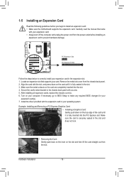
... manual that supports your operating system. Secure the card's metal bracket to the chassis back panel with your computer. If necessary, go to BIOS Setup to make any required BIOS changes for your expansion card in your card. Make sure the card is securely seated in the slot. 3. Turn on the card...
... manual that supports your operating system. Secure the card's metal bracket to the chassis back panel with your computer. If necessary, go to BIOS Setup to make any required BIOS changes for your expansion card in your card. Make sure the card is securely seated in the slot. 3. Turn on the card...

Manual
Page 22
... Activity LED: State Blinking On Description Data transmission or receiving is occurring No data transmission or receiving is one of 2560x1600 but not during the BIOS Setup or POST process. DisplayPort can support a maximum resolution of the new generation interface technologies that supports DisplayPort to this port. The following describes the...
... Activity LED: State Blinking On Description Data transmission or receiving is occurring No data transmission or receiving is one of 2560x1600 but not during the BIOS Setup or POST process. DisplayPort can support a maximum resolution of the new generation interface technologies that supports DisplayPort to this port. The following describes the...

Manual
Page 24
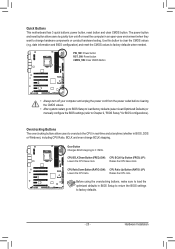
...)) 1-9 Onboard Buttons, Switches and LEDs BIOS Switch and BIOS LED Indicators The BIOS switch (M/B) allows users to easily select a different BIOS for boot up or overclocking, helping to low speed. BIOS Switch: M/B 1: Main BIOS (Boot from the main BIOS) 3: Backup BIOS (Boot from the backup BIOS) SB 1: Dual BIOS 3: Single BIOS BIOS LED Indicators: BBIOS_LED (The backup BIOS is active) MBIOS_LED (The main...
...)) 1-9 Onboard Buttons, Switches and LEDs BIOS Switch and BIOS LED Indicators The BIOS switch (M/B) allows users to easily select a different BIOS for boot up or overclocking, helping to low speed. BIOS Switch: M/B 1: Main BIOS (Boot from the main BIOS) 3: Backup BIOS (Boot from the backup BIOS) SB 1: Dual BIOS 3: Single BIOS BIOS LED Indicators: BBIOS_LED (The backup BIOS is active) MBIOS_LED (The main...
Manual
Page 25
...to factory defaults. - 25 - Gear Button Changes BCLK stepping to factory defaults when needed. Raises the CPU ratio. date information and BIOS configuration) and reset the CMOS values to 0.1 MHz. Overclocking Buttons The overclocking buttons allow users to quickly turn off or reset the computer ...in BIOS Setup to return the BIOS settings to clear the CMOS values (e.g. CPU BCLK Down Button (FREQ_DW): CPU BCLK Up Button (FREQ_UP): Lowers the CPU base ...
...to factory defaults. - 25 - Gear Button Changes BCLK stepping to factory defaults when needed. Raises the CPU ratio. date information and BIOS configuration) and reset the CMOS values to 0.1 MHz. Overclocking Buttons The overclocking buttons allow users to quickly turn off or reset the computer ...in BIOS Setup to return the BIOS settings to clear the CMOS values (e.g. CPU BCLK Down Button (FREQ_DW): CPU BCLK Up Button (FREQ_UP): Lowers the CPU base ...

Manual
Page 29
... 1 graphics cards are not configuration jumper blocks. When connecting a fan cable, be installed inside the chassis. Do not place a jumper cap on the headers. - 29 - BIOS Switcher (X58A-OC) 1 M_SATA F_PANEL(NH) F_AUDIO(H) F_USB30 TPM w/housing 3) ATX4P (PCIe Power Connector) PWM Switch (X58A-OC) The power connector provide auxiliary powDeIPr to...
... 1 graphics cards are not configuration jumper blocks. When connecting a fan cable, be installed inside the chassis. Do not place a jumper cap on the headers. - 29 - BIOS Switcher (X58A-OC) 1 M_SATA F_PANEL(NH) F_AUDIO(H) F_USB30 TPM w/housing 3) ATX4P (PCIe Power Connector) PWM Switch (X58A-OC) The power connector provide auxiliary powDeIPr to...

Manual
Page 31
.... Definition GSATA3 1 GND 7 1 97 2 TXP 3 TXN 7 1 86 4 GND 5 RXN 6 RXP 7 GND PWM Switch (SW1)(X79-UD7) BIOS_PH (GA-IVB) DIP 12345 A RAID 0 or RAID 1 configuration requires at least two hard drives. F_PANEL (H61M-D2) EBUG ORT 9) MSATA (Solid-State Drive Connector,...connector is installed with SATA 3Gb/s and SATA 1.5Gb/s standard. MSATA ACPI_CPT (GA-IVB) SMB_CPT (GA-IVB) CLR_CMOS CI DIS_ME GP15_CPT (GA-IVB) XDP_CPU XDP_PCH (GA-IVB) PWM Switch (X58A-OC) BIOS Switcher (SW4) DIP 1 23 ower connector (SATA)(X58A-OC) BIOS Switcher (X58A-OC) RT 1 M_SATA F_PANEL(NH) DIP 1 23 1 ...
.... Definition GSATA3 1 GND 7 1 97 2 TXP 3 TXN 7 1 86 4 GND 5 RXN 6 RXP 7 GND PWM Switch (SW1)(X79-UD7) BIOS_PH (GA-IVB) DIP 12345 A RAID 0 or RAID 1 configuration requires at least two hard drives. F_PANEL (H61M-D2) EBUG ORT 9) MSATA (Solid-State Drive Connector,...connector is installed with SATA 3Gb/s and SATA 1.5Gb/s standard. MSATA ACPI_CPT (GA-IVB) SMB_CPT (GA-IVB) CLR_CMOS CI DIS_ME GP15_CPT (GA-IVB) XDP_CPU XDP_PCH (GA-IVB) PWM Switch (X58A-OC) BIOS Switcher (SW4) DIP 1 23 ower connector (SATA)(X58A-OC) BIOS Switcher (X58A-OC) RT 1 M_SATA F_PANEL(NH) DIP 1 23 1 ...

Manual
Page 32
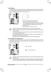
... your chassis front panel module to this header according to the pin assignments below. When connecting your system using the power switch (refer to Chapter 2, "BIOS Setup," "Power Management," for more information). •• SPEAK (Speaker, Orange): Connects to the chassis intrusion switch/sensor on the chassis that can detect if...
... your chassis front panel module to this header according to the pin assignments below. When connecting your system using the power switch (refer to Chapter 2, "BIOS Setup," "Power Management," for more information). •• SPEAK (Speaker, Orange): Connects to the chassis intrusion switch/sensor on the chassis that can detect if...
Manual
Page 33
... 5 Line Out (R) 6 GND 6 NC 7 FAUDIO_JD 7 NC 8 No Pin 8 No Pin 9 LINE2_L 9 Line Out (L) 10 GND 10 NC DIP 1 23 1 DB_PORT BIOS Switcher (X58A-OC) •• The front panel audio header supports HD audio by default. Incorrect connection between the module connector and the motherboard header...S/PDIF In cable, please contact the local dealer. 1 age measurement points(G1.Sniper 3) BIOS Switcher (SW4) Pin No. 1 2 3 Definition Power SPDIFI GND CLR_CMOS CI DIS_ME GP15_CPT (GA-IVB) XDP_CPU XDP_PCH (GA-IVB) - 33 - Definition Pin No. If you want to mute the back panel audio...
... 5 Line Out (R) 6 GND 6 NC 7 FAUDIO_JD 7 NC 8 No Pin 8 No Pin 9 LINE2_L 9 Line Out (L) 10 GND 10 NC DIP 1 23 1 DB_PORT BIOS Switcher (X58A-OC) •• The front panel audio header supports HD audio by default. Incorrect connection between the module connector and the motherboard header...S/PDIF In cable, please contact the local dealer. 1 age measurement points(G1.Sniper 3) BIOS Switcher (SW4) Pin No. 1 2 3 Definition Power SPDIFI GND CLR_CMOS CI DIS_ME GP15_CPT (GA-IVB) XDP_CPU XDP_PCH (GA-IVB) - 33 - Definition Pin No. If you want to mute the back panel audio...

Manual
Page 35
... provide one serial port via an optional COM port cable. Pin No. Definition Voltage measurement points(G1.Sniper 3) BIOS S1witcherN(SDWC4D) - 2 NSIN 9 1 10 2 3 NSOUT 4 NDTR- 5 GND PWM Switch (X58A-OC) DIP 1 23 1 ...6 NDSR7 NRTS8 NCTS- 9 NRI- 10 No Pin BIOS Switcher (X58A-OC) 1 M_SATA F_PANEL(NH) - 35 - DIP 1 23 1 DIP 1 23 1 F_USB30 F_AUDIO(H) 15) F_USB30_1/F_USB30_2 (USB...please contact the local dealer. Hardware Installation F_PANEL (H61M-D2 ACPI_CP (GA-IVB) SMB_CP (GA-IVB) CLR_CM CI DIS_ME GP15_CP...
... provide one serial port via an optional COM port cable. Pin No. Definition Voltage measurement points(G1.Sniper 3) BIOS S1witcherN(SDWC4D) - 2 NSIN 9 1 10 2 3 NSOUT 4 NDTR- 5 GND PWM Switch (X58A-OC) DIP 1 23 1 ...6 NDSR7 NRTS8 NCTS- 9 NRI- 10 No Pin BIOS Switcher (X58A-OC) 1 M_SATA F_PANEL(NH) - 35 - DIP 1 23 1 DIP 1 23 1 F_USB30 F_AUDIO(H) 15) F_USB30_1/F_USB30_2 (USB...please contact the local dealer. Hardware Installation F_PANEL (H61M-D2 ACPI_CP (GA-IVB) SMB_CP (GA-IVB) CLR_CM CI DIS_ME GP15_CP...
Manual
Page 36
... metal object like a screwdriver to clear the CMOS values (e.g. 17) BAT (Battery) The battery provides power to keep the values (such as BIOS configurations, date, and time information) in the power cord and restart your computer. •• Always turn off your computer and unplug the ... local environmental regulations. 18) CLR_CMOS (Clear CMOS Jumper) Use this jumper to touch the two pins for a few seconds. date information and BIOS configurations) and reset the CMOS values to replace the battery by removing the battery: 1. Danger of the battery (the positive side should face ...
... metal object like a screwdriver to clear the CMOS values (e.g. 17) BAT (Battery) The battery provides power to keep the values (such as BIOS configurations, date, and time information) in the power cord and restart your computer. •• Always turn off your computer and unplug the ... local environmental regulations. 18) CLR_CMOS (Clear CMOS Jumper) Use this jumper to touch the two pins for a few seconds. date information and BIOS configurations) and reset the CMOS values to replace the battery by removing the battery: 1. Danger of the battery (the positive side should face ...
Manual
Page 37
... 1 for how to clear the CMOS values.) - 37 - Inadequate BIOS flashing may result in the CMOS. BIOS includes a BIOS Setup program that searches and downloads the latest version of BIOS from the Internet and updates the BIOS. To upgrade the BIOS, use either the GIGABYTE Q-Flash or @BIOS utility. •• Q-Flash allows the user to quickly and...
... 1 for how to clear the CMOS values.) - 37 - Inadequate BIOS flashing may result in the CMOS. BIOS includes a BIOS Setup program that searches and downloads the latest version of BIOS from the Internet and updates the BIOS. To upgrade the BIOS, use either the GIGABYTE Q-Flash or @BIOS utility. •• Q-Flash allows the user to quickly and...

Manual
Page 38
... computer boots. After system restart, the device boot order will still be based on BIOS Setup settings. : Q-FLASH Press the key to access the Q-Flash utility directly without entering BIOS Setup. Note: The setting in BIOS Setup. : SYSTEM INFORMATION Press the key to display your system information. : BOOT...key or the down arrow key to select the first boot device, then press to enter BIOS Setup first. BIOS Setup - 38 - Function Keys Function Keys: : BIOS SETUP\Q-FLASH Press the key to enter BIOS Setup or to access the Q-Flash utility in Boot Menu is effective for one time ...
... computer boots. After system restart, the device boot order will still be based on BIOS Setup settings. : Q-FLASH Press the key to access the Q-Flash utility directly without entering BIOS Setup. Note: The setting in BIOS Setup. : SYSTEM INFORMATION Press the key to display your system information. : BOOT...key or the down arrow key to select the first boot device, then press to enter BIOS Setup first. BIOS Setup - 38 - Function Keys Function Keys: : BIOS SETUP\Q-FLASH Press the key to enter BIOS Setup or to access the Q-Flash utility in Boot Menu is effective for one time ...

Manual
Page 39
... the function menu in each area for quick configuration. The Main Menu of the BIOS Setup Program On the main menu of the BIOS Setup Program.) B. BIOS Setup The 3D BIOS Screen (Default) On GIGABYTE's uniquely designed 3D BIOS screen, you can click the function menu icons at the bottom of the screen... or press to switch to the main menu of the BIOS Setup program. (If a mouse is ...
... the function menu in each area for quick configuration. The Main Menu of the BIOS Setup Program On the main menu of the BIOS Setup Program.) B. BIOS Setup The 3D BIOS Screen (Default) On GIGABYTE's uniquely designed 3D BIOS screen, you can click the function menu icons at the bottom of the screen... or press to switch to the main menu of the BIOS Setup program. (If a mouse is ...

Manual
Page 40
...such as an image and save it to configure the clock, frequency, and voltages of your USB drive Main Menu: Exit the BIOS Setup program Submenus: Exit current submenu BIOS Setup Menus „„ M.I.T. Or check the system/CPU temperatures, voltages, and fan speeds. „„ System Use this... menu to your CPU and memory, etc. You can save the current BIOS settings to a profile or load optimized defaults for optimal-performance system operations. •• When the system is not stable as usual, select ...
...such as an image and save it to configure the clock, frequency, and voltages of your USB drive Main Menu: Exit the BIOS Setup program Submenus: Exit current submenu BIOS Setup Menus „„ M.I.T. Or check the system/CPU temperatures, voltages, and fan speeds. „„ System Use this... menu to your CPU and memory, etc. You can save the current BIOS settings to a profile or load optimized defaults for optimal-performance system operations. •• When the system is not stable as usual, select ...


