User Manual
Page 7
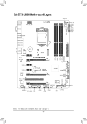
... PW_SW CMOS_SW RST_SW VCORE CPUVTT VSA CPUPLL VDIMM DDRVTT PCHIO USB3_ESATA ATX USB30_LAN VIA BAT AUDIO VL800 PCIEX1_1 Atheros GbE LAN PCIEX16 mSATA GA-Z77X-UD3H PCIEX1_2 PCIEX1_3 CODEC PCIEX8 B_BIOS BBIOS_LED MBIOS_LED M_BIOS Marvell 88SE9172 PCI PCIe to PCI Bridge PCIEX4 F_AUDIO DDR3_4 DDR3_2 DDR3_3 DDR3_1 ATX4P1 F_USB30... Intel® Z77 SATA3 1 0 SATA2 32 54 CLR_CMOS SYS_FAN1 iTE Super I/O SYS_FAN3 Debug LED (Note) SPDIF_O SYS_FAN4 TPM F_USB3 F_USB1 F_USB2 F_PANEL SW4 (Note) For debug code information, please refer to Chapter 5. - 7 -
... PW_SW CMOS_SW RST_SW VCORE CPUVTT VSA CPUPLL VDIMM DDRVTT PCHIO USB3_ESATA ATX USB30_LAN VIA BAT AUDIO VL800 PCIEX1_1 Atheros GbE LAN PCIEX16 mSATA GA-Z77X-UD3H PCIEX1_2 PCIEX1_3 CODEC PCIEX8 B_BIOS BBIOS_LED MBIOS_LED M_BIOS Marvell 88SE9172 PCI PCIe to PCI Bridge PCIEX4 F_AUDIO DDR3_4 DDR3_2 DDR3_3 DDR3_1 ATX4P1 F_USB30... Intel® Z77 SATA3 1 0 SATA2 32 54 CLR_CMOS SYS_FAN1 iTE Super I/O SYS_FAN3 Debug LED (Note) SPDIF_O SYS_FAN4 TPM F_USB3 F_USB1 F_USB2 F_PANEL SW4 (Note) For debug code information, please refer to Chapter 5. - 7 -
User Manual
Page 11
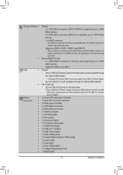
... 1 x CPU fan header 4 x fan headers 1 x front panel header 1 x front panel audio header 1 x S/PDIF Out header 3 x USB 2.0/1.1 headers 1 x USB 3.0/2.0 header 1 x Clear CMOS jumper 1 x Trusted Platform Module (TPM) header 1 x power button 1 x reset button 1 x Clear CMOS button 1 x Voltage Measurement Points 1 x BIOS Switch - 11 - Hardware Installation Storage Interface ŠŠ Š Š USB Š Š...
... 1 x CPU fan header 4 x fan headers 1 x front panel header 1 x front panel audio header 1 x S/PDIF Out header 3 x USB 2.0/1.1 headers 1 x USB 3.0/2.0 header 1 x Clear CMOS jumper 1 x Trusted Platform Module (TPM) header 1 x power button 1 x reset button 1 x Clear CMOS button 1 x Voltage Measurement Points 1 x BIOS Switch - 11 - Hardware Installation Storage Interface ŠŠ Š Š USB Š Š...
User Manual
Page 22
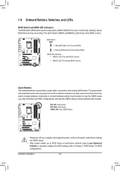
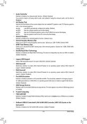
... and BIOS configurations) and reset the CMOS values to factory defaults when needed. 11 PW_SW: Power button RST_SW: Reset button CMOS_SW: Clear CMOS Button F_USB30 TPM w/housing BIOS Switcher (X58A-OC) 11 M_SATA DB_PORT F_AUDIO(H) F_PANEL(NH) •• Always turn on/off your computer and unplug the power cord from...
... and BIOS configurations) and reset the CMOS values to factory defaults when needed. 11 PW_SW: Power button RST_SW: Reset button CMOS_SW: Clear CMOS Button F_USB30 TPM w/housing BIOS Switcher (X58A-OC) 11 M_SATA DB_PORT F_AUDIO(H) F_PANEL(NH) •• Always turn on/off your computer and unplug the power cord from...
User Manual
Page 23
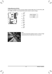
...Installation DIP 1 23 DIP 1 23 DIP 1 1 23 DIP 1 1 23 DIP 1 1 23 DIP 1 1 23 DIP 1 TPM w/housing TPM w/housing TPM w/housing Voltage Measurement PointsTwP/hMousing VoltDagBe_PmOeRasTurement module(X58A-OC) VoltDagBe_PmOeRasTurement module(X58A-OC) PCIe power connector (SATA)(X58A-OC) VoltDagBe_PmOeRasTurement module(X58A-...-OC) DIP 1 23 DIP 1 23 DIP 1 23 DIP 1 23 DIP 1 23 1 Users can use a multimeter to the pin 2 (ground). - 23 - You TPM canw/ehomusipngloy following way to measure PcCoIempopweor cnoennnecttovr (oSAlTtaA)g(Xe58sA-.OC) PWM SDwIPitch (X58A-OC) DIP 1 23 DIP 1 23...
...Installation DIP 1 23 DIP 1 23 DIP 1 1 23 DIP 1 1 23 DIP 1 1 23 DIP 1 1 23 DIP 1 TPM w/housing TPM w/housing TPM w/housing Voltage Measurement PointsTwP/hMousing VoltDagBe_PmOeRasTurement module(X58A-OC) VoltDagBe_PmOeRasTurement module(X58A-OC) PCIe power connector (SATA)(X58A-OC) VoltDagBe_PmOeRasTurement module(X58A-...-OC) DIP 1 23 DIP 1 23 DIP 1 23 DIP 1 23 DIP 1 23 1 Users can use a multimeter to the pin 2 (ground). - 23 - You TPM canw/ehomusipngloy following way to measure PcCoIempopweor cnoennnecttovr (oSAlTtaA)g(Xe58sA-.OC) PWM SDwIPitch (X58A-OC) DIP 1 23 DIP 1 23...
User Manual
Page 24
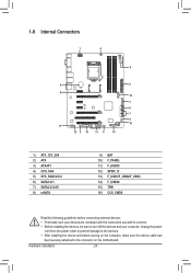
... 5 15 13 5 10 1) ATX_12V_2X4 2) ATX 3) ATX4P1 4) CPU_FAN 5) SYS_FAN1/2/3/4 6) SATA3 0/1 7) SATA2 2/3/4/5 8) mSATA 9) BAT 10) F_PANEL 11) F_AUDIO 12) SPDIF_O 13) F_USB1/F_USB2/F_USB3 14) F_USB30 15) TPM 16) CLR_CMOS Read the following guidelines before turning on the motherboard. Hardware Installation - 24 - Unplug the power cord from the power outlet to prevent damage...
... 5 15 13 5 10 1) ATX_12V_2X4 2) ATX 3) ATX4P1 4) CPU_FAN 5) SYS_FAN1/2/3/4 6) SATA3 0/1 7) SATA2 2/3/4/5 8) mSATA 9) BAT 10) F_PANEL 11) F_AUDIO 12) SPDIF_O 13) F_USB1/F_USB2/F_USB3 14) F_USB30 15) TPM 16) CLR_CMOS Read the following guidelines before turning on the motherboard. Hardware Installation - 24 - Unplug the power cord from the power outlet to prevent damage...

User Manual
Page 26
.... Definition 1 GND 2 +12V 3 Sense 4 Speed Control 1 SYS_FAN1/SYS_FAN2 SYS_FAN1/2/3: Pin No. Definition 1 GND 2 +12V /Speed Control 3 Sense 4 Reserve 1 SYS_FAN3/SYS_FAN4 SYS_FAN4: Pin No. F_AUDIO(H) F_USB30 TPM w/housing Voltage measurement module(X58A-OC) DB_PORT Pin No. When connecting a fan cable, be installed inside the chassis. 1 CPU_FAN CPU_FAN: Pin No. For optimum heat...
.... Definition 1 GND 2 +12V 3 Sense 4 Speed Control 1 SYS_FAN1/SYS_FAN2 SYS_FAN1/2/3: Pin No. Definition 1 GND 2 +12V /Speed Control 3 Sense 4 Reserve 1 SYS_FAN3/SYS_FAN4 SYS_FAN4: Pin No. F_AUDIO(H) F_USB30 TPM w/housing Voltage measurement module(X58A-OC) DB_PORT Pin No. When connecting a fan cable, be installed inside the chassis. 1 CPU_FAN CPU_FAN: Pin No. For optimum heat...
User Manual
Page 28
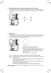
... •• Always turn off your computer and unplug the power cord. 2. F_PANEL (H61M-D2) ACPI_CPT (GA-IVB) SMB_CPT (GA-IVB) CLR_CMOS CI DIS_ME GP15_CPT (GA-IVB) XDP_CPU XDP_PCH (GA-IVB) 8) mSATA (Solid-State Drive Connector, Controlled by removing the battery: 1. Voltage measurement module(X58A-OC)...and negative terminals of explosion if the battery is replaced with a solid-state drive, the SATA2 5 connector will become unavailable. F_USB30 TPM w/housing Replace the battery. 4. Danger of the battery holder, making them short for one . When the mSATA connector is turned ...
... •• Always turn off your computer and unplug the power cord. 2. F_PANEL (H61M-D2) ACPI_CPT (GA-IVB) SMB_CPT (GA-IVB) CLR_CMOS CI DIS_ME GP15_CPT (GA-IVB) XDP_CPU XDP_PCH (GA-IVB) 8) mSATA (Solid-State Drive Connector, Controlled by removing the battery: 1. Voltage measurement module(X58A-OC)...and negative terminals of explosion if the battery is replaced with a solid-state drive, the SATA2 5 connector will become unavailable. F_USB30 TPM w/housing Replace the battery. 4. Danger of the battery holder, making them short for one . When the mSATA connector is turned ...
User Manual
Page 31
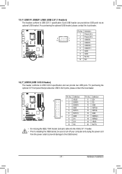
... local dealer. Pin No. DB_PORT15 SSTX2- 6 SSTX1+ 16 GND 1 20 7 GND 8 D1- 17 SSRX2+ 18 SSRX2- 9 D1+ 19 VBUS 10 NC Voltage meas2u0rementNmoodPuilne(X58A-OC) TPM •• Do not plug the IEEEw/1ho3u9si4ngbracket (2x5-pin) cable into the USB 2.0/1.1 header. •• Prior to installing the USB bracket, be sure...
... local dealer. Pin No. DB_PORT15 SSTX2- 6 SSTX1+ 16 GND 1 20 7 GND 8 D1- 17 SSRX2+ 18 SSRX2- 9 D1+ 19 VBUS 10 NC Voltage meas2u0rementNmoodPuilne(X58A-OC) TPM •• Do not plug the IEEEw/1ho3u9si4ngbracket (2x5-pin) cable into the USB 2.0/1.1 header. •• Prior to installing the USB bracket, be sure...
User Manual
Page 32
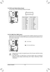
DB_PORT BIOS Switc 1 1 19 TPM w/housing 20 1 Voltage measurement module(X58A-OC) 2 Pin No. 1 2 3 4 5 6 7 8 9 10 Definition Pin No. Hardware Installation - 32 - date information and BIOS configurations) and reset the CMOS ... to BIOS Setup to load factory defaults (select Load Optimized Defaults) or manually configure the BIOS settings (refer to this jumper to factory defaults. 1 15) TPM (Trusted Platform Module Header) You may connect a TPM (Trusted Platform Module) to Chapter 2, "BIOS Setup," for a few seconds.
DB_PORT BIOS Switc 1 1 19 TPM w/housing 20 1 Voltage measurement module(X58A-OC) 2 Pin No. 1 2 3 4 5 6 7 8 9 10 Definition Pin No. Hardware Installation - 32 - date information and BIOS configurations) and reset the CMOS ... to BIOS Setup to load factory defaults (select Load Optimized Defaults) or manually configure the BIOS settings (refer to this jumper to factory defaults. 1 15) TPM (Trusted Platform Module Header) You may connect a TPM (Trusted Platform Module) to Chapter 2, "BIOS Setup," for a few seconds.
User Manual
Page 53
... to enable EHCI Hand-off feature for an operating system without EHCI Hand-off Determines whether to Enable when a TPM device is installed. `` Trusted Computing && TPM SUPPORT Enables or disables Trusted Platform Module (TPM). This item appears only when a USB storage device is installed. (Default: Disable) && OnBoard USB3.0 Controller#1 (VIA VL800 USB Controller...
... to enable EHCI Hand-off feature for an operating system without EHCI Hand-off Determines whether to Enable when a TPM device is installed. `` Trusted Computing && TPM SUPPORT Enables or disables Trusted Platform Module (TPM). This item appears only when a USB storage device is installed. (Default: Disable) && OnBoard USB3.0 Controller#1 (VIA VL800 USB Controller...

