User Guide
Page 1
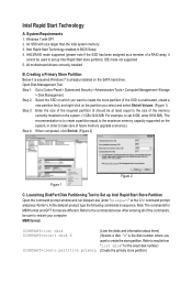
... the commands, be used to the maximum memory capacity supported on the system. (1 GB=1024 MB. At the diskpart prompt, type the following commands in BIOS Setup 4. After entering all of a RAID array, it is assumed Windows 7 is to create a partition equal to set 8 GB, enter 8192 MB). The recommendation is...
... the commands, be used to the maximum memory capacity supported on the system. (1 GB=1024 MB. At the diskpart prompt, type the following commands in BIOS Setup 4. After entering all of a RAID array, it is assumed Windows 7 is to create a partition equal to set 8 GB, enter 8192 MB). The recommendation is...
User Guide
Page 2
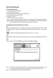
... to the Peripherals menu and set Intel Rapid Start Technology to enter the BIOS Setup program. While in the notification area. The Timer slider in BIOS Setup 1. When the system restarts, press to Enabled. 2. Save the settings and exit BIOS Setup. After the installation is volume of the selected disk and the volumes...
... to the Peripherals menu and set Intel Rapid Start Technology to enter the BIOS Setup program. While in the notification area. The Timer slider in BIOS Setup 1. When the system restarts, press to Enabled. 2. Save the settings and exit BIOS Setup. After the installation is volume of the selected disk and the volumes...
User Guide
Page 3
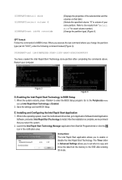
Step 2: As shown in the left screenshot below, click the Start button and type regedit in BIOS Setup 2. This feature works best with programs designed to work with the Internet to obtain their data while your computer when completed. A. Normal network connection B. ...
Step 2: As shown in the left screenshot below, click the Start button and type regedit in BIOS Setup 2. This feature works best with programs designed to work with the Internet to obtain their data while your computer when completed. A. Normal network connection B. ...
User Guide
Page 5
... be used for the Intel SATA controllers in the notification area and double-click it to the SATA disk. Step 2: Find the IRST icon in BIOS Setup 4. The maximum cache memory size is 11.0 or above. Restart your data. (Note 2) The operating system must be lost once you back up the...
... be used for the Intel SATA controllers in the notification area and double-click it to the SATA disk. Step 2: Find the IRST icon in BIOS Setup 4. The maximum cache memory size is 11.0 or above. Restart your data. (Note 2) The operating system must be lost once you back up the...
User Manual
Page 3
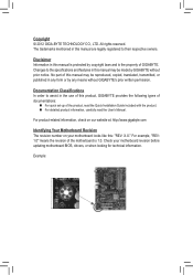
... are legally registered to their respective owners. For product-related information, check on our website at: http://www.gigabyte.com Identifying Your Motherboard Revision The revision number on your motherboard revision before updating motherboard BIOS, drivers, or when looking for technical information. Example: Disclaimer Information in this manual is protected by copyright...
... are legally registered to their respective owners. For product-related information, check on our website at: http://www.gigabyte.com Identifying Your Motherboard Revision The revision number on your motherboard revision before updating motherboard BIOS, drivers, or when looking for technical information. Example: Disclaimer Information in this manual is protected by copyright...
User Manual
Page 4
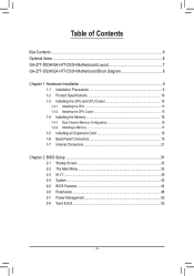
Table of Contents Box Contents...6 Optional Items...6 GA-Z77-DS3H/GA-H77-DS3H Motherboard Layout 7 GA-Z77-DS3H/GA-H77-DS3H Motherboard Block Diagram 8 Chapter 1 Hardware Installation 9 1-1 Installation Precautions 9 1-2 Product Specifications 10 1-3 Installing the CPU and CPU... Installing a Memory 17 1-5 Installing an Expansion Card 18 1-6 Back Panel Connectors 19 1-7 Internal Connectors 21 Chapter 2 BIOS Setup 31 2-1 Startup Screen 32 2-2 The Main Menu 33 2-3 M.I.T...35 2-4 System...43 2-5 BIOS Features 44 2-6 Peripherals...46 2-7 Power Management 50 2-8 Save & Exit...52 - 4 -
Table of Contents Box Contents...6 Optional Items...6 GA-Z77-DS3H/GA-H77-DS3H Motherboard Layout 7 GA-Z77-DS3H/GA-H77-DS3H Motherboard Block Diagram 8 Chapter 1 Hardware Installation 9 1-1 Installation Precautions 9 1-2 Product Specifications 10 1-3 Installing the CPU and CPU... Installing a Memory 17 1-5 Installing an Expansion Card 18 1-6 Back Panel Connectors 19 1-7 Internal Connectors 21 Chapter 2 BIOS Setup 31 2-1 Startup Screen 32 2-2 The Main Menu 33 2-3 M.I.T...35 2-4 System...43 2-5 BIOS Features 44 2-6 Peripherals...46 2-7 Power Management 50 2-8 Save & Exit...52 - 4 -
User Manual
Page 5
... 54 3-4 Contact...55 3-5 System...55 3-6 Download Center 56 3-7 New Program 56 Chapter 4 Unique Features 57 4-1 Xpress Recovery2 57 4-2 BIOS Update Utilities 60 4-2-1 Updating the BIOS with the Q-Flash Utility 60 4-2-2 Updating the BIOS with the @BIOS Utility 63 4-3 Q-Share...64 4-4 eXtreme Hard Drive (X.H.D 65 4-5 Auto Green...66 4-6 Intel Rapid Start Technology 67 4-7 Intel Smart...
... 54 3-4 Contact...55 3-5 System...55 3-6 Download Center 56 3-7 New Program 56 Chapter 4 Unique Features 57 4-1 Xpress Recovery2 57 4-2 BIOS Update Utilities 60 4-2-1 Updating the BIOS with the Q-Flash Utility 60 4-2-2 Updating the BIOS with the @BIOS Utility 63 4-3 Q-Share...64 4-4 eXtreme Hard Drive (X.H.D 65 4-5 Auto Green...66 4-6 Intel Rapid Start Technology 67 4-7 Intel Smart...
User Manual
Page 8
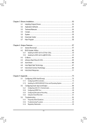
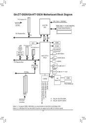
GA-Z77-DS3H/GA-H77-DS3H Motherboard Block Diagram 1 PCI Express x16 PCIe CLK (100 MHz) ... x1 Intel® Z77j/ H77k PCI Express Bus x1 PCIe to USB 2.0 transfer speed. - 8 - k Only for GA-H77-DS3H. (Note 1) To support DDR3 1600 MHz, you must install an Intel 22nm (Ivy Bridge) CPU. (Note 2) In Windows...BIOS 2 SATA 6Gb/s 3 SATA 3Gb/s 1 mSATA 8 USB 2.0/1.1 PCI Bus CODEC 4 USB 3.0 (Note 2)/2.0 LPC Bus iTE COM Super I/O PS/2 KB/Mouse MIC (Center/Subwoofer Speaker Out) Line Out (Front Speaker Out) Line In (Rear Speaker Out) S/PDIF Out 2 PCI PCI CLK (33 MHz) j Only for GA-Z77-DS3H...
GA-Z77-DS3H/GA-H77-DS3H Motherboard Block Diagram 1 PCI Express x16 PCIe CLK (100 MHz) ... x1 Intel® Z77j/ H77k PCI Express Bus x1 PCIe to USB 2.0 transfer speed. - 8 - k Only for GA-H77-DS3H. (Note 1) To support DDR3 1600 MHz, you must install an Intel 22nm (Ivy Bridge) CPU. (Note 2) In Windows...BIOS 2 SATA 6Gb/s 3 SATA 3Gb/s 1 mSATA 8 USB 2.0/1.1 PCI Bus CODEC 4 USB 3.0 (Note 2)/2.0 LPC Bus iTE COM Super I/O PS/2 KB/Mouse MIC (Center/Subwoofer Speaker Out) Line Out (Front Speaker Out) Line In (Rear Speaker Out) S/PDIF Out 2 PCI PCI CLK (33 MHz) j Only for GA-Z77-DS3H...
User Manual
Page 12
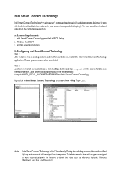
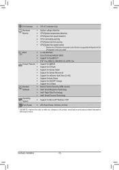
... will depend on the CPU/system cooler you install. 2 x 64 Mbit flash Use of licensed AMI EFI BIOS Support for DualBIOS™ PnP 1.0a, DMI 2.0, SM BIOS 2.6, ACPI 2.0a Support for @BIOS Support for Q-Flash Support for Xpress Install Support for Xpress Recovery2 Support for eXtreme Hard Drive (X.H.D) Support for ...Intel® Rapid Start Technology Intel® Smart Connect Technology Support for Microsoft® Windows 7/XP ATX Form Factor; 30.5cm x 21.5cm * GIGABYTE reserves the right to make any changes to the product specifications and product-related information without prior notice.
... will depend on the CPU/system cooler you install. 2 x 64 Mbit flash Use of licensed AMI EFI BIOS Support for DualBIOS™ PnP 1.0a, DMI 2.0, SM BIOS 2.6, ACPI 2.0a Support for @BIOS Support for Q-Flash Support for Xpress Install Support for Xpress Recovery2 Support for eXtreme Hard Drive (X.H.D) Support for ...Intel® Rapid Start Technology Intel® Smart Connect Technology Support for Microsoft® Windows 7/XP ATX Form Factor; 30.5cm x 21.5cm * GIGABYTE reserves the right to make any changes to the product specifications and product-related information without prior notice.
User Manual
Page 16
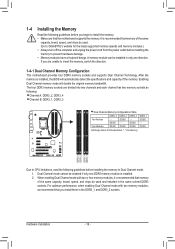
...memory of the same capacity, brand, speed, and chips be enabled if only one direction. The four DDR3 memory sockets are unable to GIGABYTE's website for the latest supported memory speeds and memory modules.) •• Always turn off the computer and unplug the power cord from...the motherboard supports the memory. For optimum performance, when enabling Dual Channel mode with two or four memory modules, it is installed, the BIOS will double the original memory bandwidth. If you install them in only one DDR3 memory module is installed. 2. Enabling Dual Channel memory ...
...memory of the same capacity, brand, speed, and chips be enabled if only one direction. The four DDR3 memory sockets are unable to GIGABYTE's website for the latest supported memory speeds and memory modules.) •• Always turn off the computer and unplug the power cord from...the motherboard supports the memory. For optimum performance, when enabling Dual Channel mode with two or four memory modules, it is installed, the BIOS will double the original memory bandwidth. If you install them in only one DDR3 memory module is installed. 2. Enabling Dual Channel memory ...
User Manual
Page 18
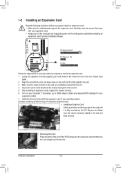
After installing all expansion cards, replace the chassis cover(s). 6. If necessary, go to BIOS Setup to make any required BIOS changes for your computer. Remove the metal slot cover from the power outlet before you begin to correctly install your card. Align the card with a ...
After installing all expansion cards, replace the chassis cover(s). 6. If necessary, go to BIOS Setup to make any required BIOS changes for your computer. Remove the metal slot cover from the power outlet before you begin to correctly install your card. Align the card with a ...
User Manual
Page 19
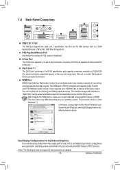
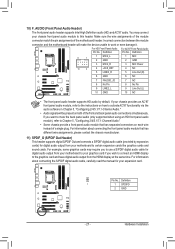
... HDMI device, make sure to set Intel(R) Display Audio to 192KHz/24bit 8-channel LPCM audio output. The screenshot below is 1920x1200, but not during the BIOS Setup or POST process. (Note) The DVI-D port does not support D-Sub connection by adapter. - 19 -
... HDMI device, make sure to set Intel(R) Display Audio to 192KHz/24bit 8-channel LPCM audio output. The screenshot below is 1920x1200, but not during the BIOS Setup or POST process. (Note) The DVI-D port does not support D-Sub connection by adapter. - 19 -
User Manual
Page 25
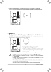
...or local dealer if you are not able to replace the battery by the Intel Z77/H77 Chipset) The mSATA connector conforms to SATA 3Gb/s standard and can connect to keep the values (such as BIOS configurations, daXtDeP, _aCnPdUtime information) er 3) in the power cord and restart your...-OC) 1 M_SATA Voltage measurement module(X58A-OC) PWM Switch (X58A-OC) mSATA ACPI_CPT (GA-IVB) DIP 1 23 1 DIP 1 23 1 DIP 1 23 PCIe power connector (SATA)(X58A-OC) SMB_CPT (GA-IVB) CLR_CMOS CI DIS_ME GP15_CPT (GA-IVB) 8) BAT (Battery) The battery provides power to a single solid-state drive. Hardware...
...or local dealer if you are not able to replace the battery by the Intel Z77/H77 Chipset) The mSATA connector conforms to SATA 3Gb/s standard and can connect to keep the values (such as BIOS configurations, daXtDeP, _aCnPdUtime information) er 3) in the power cord and restart your...-OC) 1 M_SATA Voltage measurement module(X58A-OC) PWM Switch (X58A-OC) mSATA ACPI_CPT (GA-IVB) DIP 1 23 1 DIP 1 23 1 DIP 1 23 PCIe power connector (SATA)(X58A-OC) SMB_CPT (GA-IVB) CLR_CMOS CI DIS_ME GP15_CPT (GA-IVB) 8) BAT (Battery) The battery provides power to a single solid-state drive. Hardware...
User Manual
Page 26
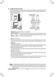
... of power switch, reset switch, power LED, hard drive activity LED, speaker and etc. When connecting your system using the power switch (refer to Chapter 2, "BIOS Setup," "Power Management," for more information). • SPEAK (Speaker, Orange): Connects to the speaker on the chassis front panel. The LED is off your chassis...
... of power switch, reset switch, power LED, hard drive activity LED, speaker and etc. When connecting your system using the power switch (refer to Chapter 2, "BIOS Setup," "Power Management," for more information). • SPEAK (Speaker, Orange): Connects to the speaker on the chassis front panel. The LED is off your chassis...
User Manual
Page 27
... the graphics card and have digital audio output from the HDMI display at the same time. Definition XDP_CPU 1 1 SPDIFO XDP_PCH 2 GND (GA-IVB) - 27 - If you want to mute the back panel audio (only supported when using an HD front panel audio Voltage meamsuordemuelen... 7 NC 8 No Pin 8 No Pin 9 LINE2_L 9 Line Out (L) 10 GND 10 NC F_PANEL (H61M-D2) DIP 1 23 1 DIP 1 23 1 DIP 1 23 1 BIOS Switcher (X58A-OC) DB_•P•ORTThe front panel audio header supports HD audio by expansion cardsP)CfIoerpodwigeritcaolnaneucdtoiro(SoAuTtAp)(uXt5f8rAo-mOC)your motherboard to use...
... the graphics card and have digital audio output from the HDMI display at the same time. Definition XDP_CPU 1 1 SPDIFO XDP_PCH 2 GND (GA-IVB) - 27 - If you want to mute the back panel audio (only supported when using an HD front panel audio Voltage meamsuordemuelen... 7 NC 8 No Pin 8 No Pin 9 LINE2_L 9 Line Out (L) 10 GND 10 NC F_PANEL (H61M-D2) DIP 1 23 1 DIP 1 23 1 DIP 1 23 1 BIOS Switcher (X58A-OC) DB_•P•ORTThe front panel audio header supports HD audio by expansion cardsP)CfIoerpodwigeritcaolnaneucdtoiro(SoAuTtAp)(uXt5f8rAo-mOC)your motherboard to use...
User Manual
Page 28
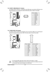
... two USB 3.0/2.0 ports, please contact the local dealer. 20 10 11 TPM w/housing Pin No. 1 2 3 4 5 6 7 8 9 10 Definition VBUS SSRX1SSRX1+ GND SSTX1SSTX1+ GND D1D1+ NC DB_PORT 1 1 BIOS Switche 1 1 Pin No. Definition 11 VoDlt2ag+e measurement module(X58A-OC) 12 D213 GND 14 SSTX2+ 15 SSTX216 GND 17 SSPRCXIe2p+ower connector (SATA)(X58A-OC...
... two USB 3.0/2.0 ports, please contact the local dealer. 20 10 11 TPM w/housing Pin No. 1 2 3 4 5 6 7 8 9 10 Definition VBUS SSRX1SSRX1+ GND SSTX1SSTX1+ GND D1D1+ NC DB_PORT 1 1 BIOS Switche 1 1 Pin No. Definition 11 VoDlt2ag+e measurement module(X58A-OC) 12 D213 GND 14 SSTX2+ 15 SSTX216 GND 17 SSPRCXIe2p+ower connector (SATA)(X58A-OC...
User Manual
Page 29
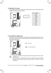
...an optional COM port cable. Hardware Installation For purchasing the optional COM port cable, please contact the local dealer. date information and BIOS configurations) and reset the CMOS values to clear the CMOS values (e.g. To clear the CMOS values, use a metal object like a screwdriver... to Chapter 2, "BIOS Setup," for a few seconds. Definition 1 NDCD- 2 NSIN 9 1 10 2 3 NSOUT 4 NDTR- 5 GND 6 NDSR- 7 NRTS- 8 NCTS- 9 NRI- 10 No Pin 15) CLR_CMOS (...
...an optional COM port cable. Hardware Installation For purchasing the optional COM port cable, please contact the local dealer. date information and BIOS configurations) and reset the CMOS values to clear the CMOS values (e.g. To clear the CMOS values, use a metal object like a screwdriver... to Chapter 2, "BIOS Setup," for a few seconds. Definition 1 NDCD- 2 NSIN 9 1 10 2 3 NSOUT 4 NDTR- 5 GND 6 NDSR- 7 NRTS- 8 NCTS- 9 NRI- 10 No Pin 15) CLR_CMOS (...
User Manual
Page 31
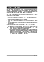
... program that you not alter the default settings (unless you not flash the BIOS. To upgrade the BIOS, use either the GIGABYTE Q-Flash or @BIOS utility. •• Q-Flash allows the user to Chapter 4, "BIOS Update Utilities." •• Because BIOS flashing is potentially risky, if you do it is a Windows-based utility that you need...
... program that you not alter the default settings (unless you not flash the BIOS. To upgrade the BIOS, use either the GIGABYTE Q-Flash or @BIOS utility. •• Q-Flash allows the user to Chapter 4, "BIOS Update Utilities." •• Because BIOS flashing is potentially risky, if you do it is a Windows-based utility that you need...
User Manual
Page 32
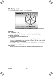
...the key to display your system information. : BOOT MENU Boot Menu allows you to accept. Function Keys Function Keys: : BIOS SETUP\Q-FLASH Press the key to enter BIOS Setup or to access the Q-Flash utility in Boot Menu is effective for one time only. 2-1 Startup Screen The following ... the first boot device, then press to set the first boot device without having to enter BIOS Setup first. BIOS Setup - 32 - After system restart, the device boot order will still be based on BIOS Setup settings. : Q-FLASH Press the key to access the Q-Flash utility directly without entering...
...the key to display your system information. : BOOT MENU Boot Menu allows you to accept. Function Keys Function Keys: : BIOS SETUP\Q-FLASH Press the key to enter BIOS Setup or to access the Q-Flash utility in Boot Menu is effective for one time only. 2-1 Startup Screen The following ... the first boot device, then press to set the first boot device without having to enter BIOS Setup first. BIOS Setup - 32 - After system restart, the device boot order will still be based on BIOS Setup settings. : Q-FLASH Press the key to access the Q-Flash utility directly without entering...
User Manual
Page 33
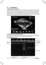
... GIGABYTE's uniquely designed 3D BIOS screen, you can use your mouse to move among the items and press to 3D BIOS screen Setup Menus Enter Q-Flash Select Default Language Help Function Keys Configuration Items Current Settings - 33 - The Main Menu of the BIOS Setup Program On the main menu of the BIOS Setup Program.) B. BIOS Setup...
... GIGABYTE's uniquely designed 3D BIOS screen, you can use your mouse to move among the items and press to 3D BIOS screen Setup Menus Enter Q-Flash Select Default Language Help Function Keys Configuration Items Current Settings - 33 - The Main Menu of the BIOS Setup Program On the main menu of the BIOS Setup Program.) B. BIOS Setup...


