
Manual
Page 1
...On Self-Test). The maximum cache memory size is recommended that you also need an SSD to the SATA disk 4. Then save changes and exit BIOS Setup. Installing a conventional SATA hard disk and a solid-state drive (SSD): Besides the conventional SATA disk, you back up the hard disk before...Move Enter: Select F5: Previous Values +/-/PU/PD: Value F10: Save F6: Fail-Safe Defaults ESC: Exit F1: General Help F7: Optimized Defaults The BIOS Setup menus described here may differ from the exact settings for storing your data. 2. Installing the operating system and drivers to make it work as...
...On Self-Test). The maximum cache memory size is recommended that you also need an SSD to the SATA disk 4. Then save changes and exit BIOS Setup. Installing a conventional SATA hard disk and a solid-state drive (SSD): Besides the conventional SATA disk, you back up the hard disk before...Move Enter: Select F5: Previous Values +/-/PU/PD: Value F10: Save F6: Fail-Safe Defaults ESC: Exit F1: General Help F7: Optimized Defaults The BIOS Setup menus described here may differ from the exact settings for storing your data. 2. Installing the operating system and drivers to make it work as...

Manual
Page 2
Installing the operating system and drivers to the SATA disk: After setting the BIOS, you can begin to install all motherboard drivers, including the Intel Rapid Storage Technology driver. After the installation is 10.5 or above and restarting your ...
Installing the operating system and drivers to the SATA disk: After setting the BIOS, you can begin to install all motherboard drivers, including the Intel Rapid Storage Technology driver. After the installation is 10.5 or above and restarting your ...
Manual
Page 3
...1.0. For product-related information, check on our website at: http://www.gigabyte.com Identifying Your Motherboard Revision The revision number on your motherboard revision before updating motherboard BIOS, drivers, or when looking for technical information. Changes to their respective ...owners. The trademarks mentioned in any form or by GIGABYTE without GIGABYTE's prior written permission. Example: For example, "REV:...
...1.0. For product-related information, check on our website at: http://www.gigabyte.com Identifying Your Motherboard Revision The revision number on your motherboard revision before updating motherboard BIOS, drivers, or when looking for technical information. Changes to their respective ...owners. The trademarks mentioned in any form or by GIGABYTE without GIGABYTE's prior written permission. Example: For example, "REV:...
Manual
Page 4
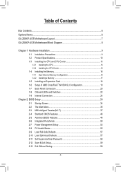
Table of Contents Box Contents...6 Optional Items...6 GA-Z68XP-UD5 Motherboard Layout 7 GA-Z68XP-UD5 Motherboard Block Diagram 8 Chapter 1 Hardware Installation 9 1-1 Installation Precautions 9 1-2 Product Specifications 10 1-3 Installing the CPU and CPU Cooler...Panel Connectors 20 1-8 Onboard LEDs and Switches 22 1-9 Internal Connectors 24 Chapter 2 BIOS Setup 33 2-1 Startup Screen 34 2-2 The Main Menu 35 2-3 MB Intelligent Tweaker(M.I.T 37 2-4 Standard CMOS Features 46 2-5 Advanced BIOS Features 48 2-6 Integrated Peripherals 50 2-7 Power Management Setup 53 2-8 PC Health Status...
Table of Contents Box Contents...6 Optional Items...6 GA-Z68XP-UD5 Motherboard Layout 7 GA-Z68XP-UD5 Motherboard Block Diagram 8 Chapter 1 Hardware Installation 9 1-1 Installation Precautions 9 1-2 Product Specifications 10 1-3 Installing the CPU and CPU Cooler...Panel Connectors 20 1-8 Onboard LEDs and Switches 22 1-9 Internal Connectors 24 Chapter 2 BIOS Setup 33 2-1 Startup Screen 34 2-2 The Main Menu 35 2-3 MB Intelligent Tweaker(M.I.T 37 2-4 Standard CMOS Features 46 2-5 Advanced BIOS Features 48 2-6 Integrated Peripherals 50 2-7 Power Management Setup 53 2-8 PC Health Status...
Manual
Page 5
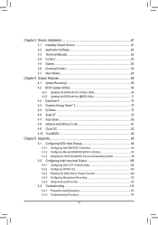
... 62 3-4 Contact...63 3-5 System...63 3-6 Download Center 64 3-7 New Utilities...64 Chapter 4 Unique Features 65 4-1 Xpress Recovery2 65 4-2 BIOS Update Utilities 68 4-2-1 Updating the BIOS with the Q-Flash Utility 68 4-2-2 Updating the BIOS with the @BIOS Utility 71 4-3 EasyTune 6...72 4-4 Dynamic Energy Saver™ 2 73 4-5 Q-Share...75 4-6 Smart 6™ ...76 4-7 Auto Green...80 4-8 eXtreme...
... 62 3-4 Contact...63 3-5 System...63 3-6 Download Center 64 3-7 New Utilities...64 Chapter 4 Unique Features 65 4-1 Xpress Recovery2 65 4-2 BIOS Update Utilities 68 4-2-1 Updating the BIOS with the Q-Flash Utility 68 4-2-2 Updating the BIOS with the @BIOS Utility 71 4-3 EasyTune 6...72 4-4 Dynamic Energy Saver™ 2 73 4-5 Q-Share...75 4-6 Smart 6™ ...76 4-7 Auto Green...80 4-8 eXtreme...
Manual
Page 8
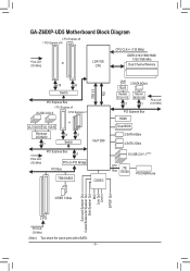
GA-Z68XP-UD5 Motherboard Block Diagram 2 PCI Express x8 1 PCI Express x16 CPU CLK+/- (133 MHz) PCIe CLK or (100 MHz) LGA1155 CPU DDR3 2133/1866/1600/ 1333/...® Z68 TSB43AB23 CODEC DMI 2.0 FDI LAN 2 SATA 6Gb/s RJ45 Realtek RTL8111E x1 Marvell 88SE9128 x1 PCIe CLK (100 MHz) PCI Express Bus HDMI Dual BIOS 2 SATA 6Gb/s 4 SATA 3Gb/s 10 USB 2.0/1.1 (Note) LPC iTE Bus IT8728 PS/2 KB/Mouse 3 IEEE 1394a Surround Speaker Out Center/Subwoofer Speaker Out Side Speaker...
GA-Z68XP-UD5 Motherboard Block Diagram 2 PCI Express x8 1 PCI Express x16 CPU CLK+/- (133 MHz) PCIe CLK or (100 MHz) LGA1155 CPU DDR3 2133/1866/1600/ 1333/...® Z68 TSB43AB23 CODEC DMI 2.0 FDI LAN 2 SATA 6Gb/s RJ45 Realtek RTL8111E x1 Marvell 88SE9128 x1 PCIe CLK (100 MHz) PCI Express Bus HDMI Dual BIOS 2 SATA 6Gb/s 4 SATA 3Gb/s 10 USB 2.0/1.1 (Note) LPC iTE Bus IT8728 PS/2 KB/Mouse 3 IEEE 1394a Surround Speaker Out Center/Subwoofer Speaker Out Side Speaker...
Manual
Page 12
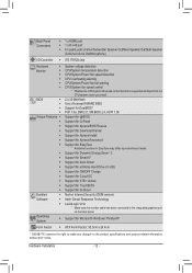
...flash ŠŠ Use of licensed AWARD BIOS ŠŠ Support for DualBIOS™ ŠŠ PnP 1.0a, DMI 2.0, SM BIOS 2.4, ACPI 1.0b Unique Features ŠŠ Support for @BIOS ŠŠ Support for Q-Flash ŠŠ Support for Xpress BIOS Rescue ŠŠ Support for Download Center ... ŠŠ Support for Microsoft® Windows 7/Vista/XP Form Factor ŠŠ ATX Form Factor; 30.5cm x 24.4cm * GIGABYTE reserves the right to make any changes to the integrated graphics port on the CPU/system cooler you install. Back Panel Connectors ŠŠ...
...flash ŠŠ Use of licensed AWARD BIOS ŠŠ Support for DualBIOS™ ŠŠ PnP 1.0a, DMI 2.0, SM BIOS 2.4, ACPI 1.0b Unique Features ŠŠ Support for @BIOS ŠŠ Support for Q-Flash ŠŠ Support for Xpress BIOS Rescue ŠŠ Support for Download Center ... ŠŠ Support for Microsoft® Windows 7/Vista/XP Form Factor ŠŠ ATX Form Factor; 30.5cm x 24.4cm * GIGABYTE reserves the right to make any changes to the integrated graphics port on the CPU/system cooler you install. Back Panel Connectors ŠŠ...
Manual
Page 16
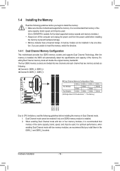
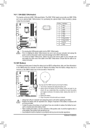
...that memory of the memory. For optimum performance, when enabling Dual Channel mode with two or four memory modules, it is installed, the BIOS will double the original memory bandwidth. A memory module can be used . Enabling Dual Channel memory mode will automatically detect the specifications and ...memory: •• Make sure that you install them in Dual Channel mode. 111 Dual Channel mode cannot be used . (Go to GIGABYTE's website for the latest supported memory speeds and memory modules.) •• Always turn off the computer and unplug the power cord from the...
...that memory of the memory. For optimum performance, when enabling Dual Channel mode with two or four memory modules, it is installed, the BIOS will double the original memory bandwidth. A memory module can be used . Enabling Dual Channel memory mode will automatically detect the specifications and ...memory: •• Make sure that you install them in Dual Channel mode. 111 Dual Channel mode cannot be used . (Go to GIGABYTE's website for the latest supported memory speeds and memory modules.) •• Always turn off the computer and unplug the power cord from the...
Manual
Page 18
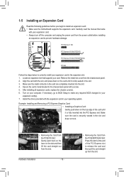
...card until it is securely seated in the expansion slot. 1. Secure the card's metal bracket to prevent hardware damage. If necessary, go to BIOS Setup to install an expansion card: •• Make sure the motherboard supports the expansion card. Align the card with your expansion card.... PCI Express slot to release the card and then pull the card straight up from the power outlet before you begin to make any required BIOS changes for your expansion card(s). 7. Example: Installing and Removing a PCI Express Graphics Card: • Installing a Graphics Card: Gently push down on ...
...card until it is securely seated in the expansion slot. 1. Secure the card's metal bracket to prevent hardware damage. If necessary, go to BIOS Setup to install an expansion card: •• Make sure the motherboard supports the expansion card. Align the card with your expansion card.... PCI Express slot to release the card and then pull the card straight up from the power outlet before you begin to make any required BIOS changes for your expansion card(s). 7. Example: Installing and Removing a PCI Express Graphics Card: • Installing a Graphics Card: Gently push down on ...
Manual
Page 22
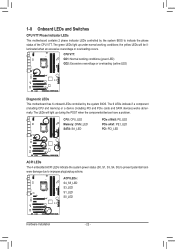
... up under normal working conditions (green LED) GD2: Excessive overvoltage or overloading (yellow LED) Diagnostic LEDs This motherboard has 6 onboard LEDs controlled by the system BIOS to improper plug/unplug actions. 1-8 Onboard LEDs and Switches CPU VTT Phase Indicator LEDs This motherboard contains 2 phase indicator LEDs controlled by the system...
... up under normal working conditions (green LED) GD2: Excessive overvoltage or overloading (yellow LED) Diagnostic LEDs This motherboard has 6 onboard LEDs controlled by the system BIOS to improper plug/unplug actions. 1-8 Onboard LEDs and Switches CPU VTT Phase Indicator LEDs This motherboard contains 2 phase indicator LEDs controlled by the system...
Manual
Page 23
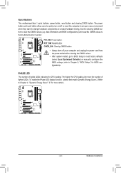
... before clearing the CMOS values. •• After system restart, go to BIOS Setup to load factory defaults (select Load Optimized Defaults) or manually configure the BIOS settings (refer to Chapter 2, "BIOS Setup," for more the number of lighted LEDs indicates the CPU loading. To...Energy Saver 2. Quick Buttons This motherboard has 3 quick buttons: power button, reset button and clearing CMOS button. Hardware Installation date information and BIOS configurations) and reset the CMOS values to clear the CMOS values (e.g. The higher the CPU loading, the more details. - 23 - Refer...
... before clearing the CMOS values. •• After system restart, go to BIOS Setup to load factory defaults (select Load Optimized Defaults) or manually configure the BIOS settings (refer to Chapter 2, "BIOS Setup," for more the number of lighted LEDs indicates the CPU loading. To...Energy Saver 2. Quick Buttons This motherboard has 3 quick buttons: power button, reset button and clearing CMOS button. Hardware Installation date information and BIOS configurations) and reset the CMOS values to clear the CMOS values (e.g. The higher the CPU loading, the more details. - 23 - Refer...
Manual
Page 28
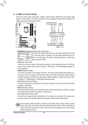
...data. • RES (Reset Switch, Green): Connects to indicate the problem. The LED is on when the hard drive is detected, the BIOS may issue beeps in S1 sleep state. A front panel module mainly consists of power switch, reset switch, power LED, hard drive activity LED...chassis front panel. This function requires a chassis with a chassis intrusion switch/sensor. When connecting your system using the power switch (refer to Chapter 2, "BIOS Setup," "Power Management Setup," for information about beep codes. • HD (Hard Drive Activity LED, Blue) Connects to the pin assignments below. ...
...data. • RES (Reset Switch, Green): Connects to indicate the problem. The LED is on when the hard drive is detected, the BIOS may issue beeps in S1 sleep state. A front panel module mainly consists of power switch, reset switch, power LED, hard drive activity LED...chassis front panel. This function requires a chassis with a chassis intrusion switch/sensor. When connecting your system using the power switch (refer to Chapter 2, "BIOS Setup," "Power Management Setup," for information about beep codes. • HD (Hard Drive Activity LED, Blue) Connects to the pin assignments below. ...
Manual
Page 30
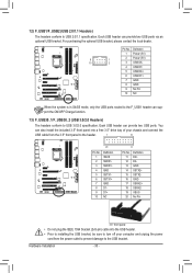
... USB 2.0/1.1 specification. Definition 1 VBUS 11 D2+ 2 SSRX1- 12 D2- 3 SSRX1+ 13 GND 4 GND 14 SSTX2+ 5 SSTX1- 15 SSTX2- 6 SSTX1+ 16 GND 7 GND 17 SSRX2+ DB_PORT BIOS 8 D1- 18 SSRX2- 9 D1+ 19 VBUS 10 NC 20 No Pin TPM w/housing Voltage measurement module(X58A-OC) PW 3.5" front panel •• Do not...
... USB 2.0/1.1 specification. Definition 1 VBUS 11 D2+ 2 SSRX1- 12 D2- 3 SSRX1+ 13 GND 4 GND 14 SSTX2+ 5 SSTX1- 15 SSTX2- 6 SSTX1+ 16 GND 7 GND 17 SSRX2+ DB_PORT BIOS 8 D1- 18 SSRX2- 9 D1+ 19 VBUS 10 NC 20 No Pin TPM w/housing Voltage measurement module(X58A-OC) PW 3.5" front panel •• Do not...
Manual
Page 31
... to the IEEE 1394a device. Ensure that the cable is securely connected. 15) BAT (Battery) The battery provides power to keep the values (such as BIOS configurations, date, and time information) in the power cord and restart your computer. •• Always turn off . You may be lost. Danger of the...
... to the IEEE 1394a device. Ensure that the cable is securely connected. 15) BAT (Battery) The battery provides power to keep the values (such as BIOS configurations, date, and time information) in the power cord and restart your computer. •• Always turn off . You may be lost. Danger of the...

Manual
Page 33
..., if you need to) to activate certain system features. BIOS includes a BIOS Setup program that searches and downloads the latest version of BIOS from the Internet and updates the BIOS. To upgrade the BIOS, use either the GIGABYTE Q-Flash or @BIOS utility. •• Q-Flash allows the user to clear...that allows the user to modify basic system configuration settings or to prevent system instability or other unexpected results. Chapter 2 BIOS Setup BIOS (Basic Input and Output System) records hardware parameters of the system in the CMOS on the motherboard supplies the necessary ...
..., if you need to) to activate certain system features. BIOS includes a BIOS Setup program that searches and downloads the latest version of BIOS from the Internet and updates the BIOS. To upgrade the BIOS, use either the GIGABYTE Q-Flash or @BIOS utility. •• Q-Flash allows the user to clear...that allows the user to modify basic system configuration settings or to prevent system instability or other unexpected results. Chapter 2 BIOS Setup BIOS (Basic Input and Output System) records hardware parameters of the system in the CMOS on the motherboard supplies the necessary ...
Manual
Page 34
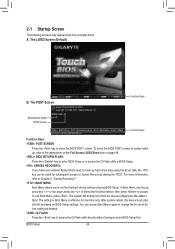
... Screen The following screens may appear when the computer boots. Motherboard Model BIOS Version Z68XP-UD5 E3 . . . . : BIOS Setup : XpressRecovery2 : Boot Menu : Qflash 05/16/2011-Z68-7A89WG0MC-00 Function Keys Function Keys Function Keys: : POST SCREEN Press the key to enter BIOS Setup first. In Boot Menu, use the up hard drive data using...
... Screen The following screens may appear when the computer boots. Motherboard Model BIOS Version Z68XP-UD5 E3 . . . . : BIOS Setup : XpressRecovery2 : Boot Menu : Qflash 05/16/2011-Z68-7A89WG0MC-00 Function Keys Function Keys Function Keys: : POST SCREEN Press the key to enter BIOS Setup first. In Boot Menu, use the up hard drive data using...

Manual
Page 35
... Saving ESC: Quit F8: Q-Flash Select Item F10: Save & Exit Setup Change CPU's Clock & Voltage F11: Save CMOS to BIOS F12: Load CMOS from BIOS BIOS Setup Program Function Keys Move the selection bar to select an item Execute command or enter the submenu Main Menu: Exit the... settings for the current submenus Access the Q-Flash utility Display system information Save all the changes and exit the BIOS Setup program Save CMOS to BIOS Load CMOS from BIOS Main Menu Help The on-screen description of a highlighted setup option is not stable as shown below) appears ...
... Saving ESC: Quit F8: Q-Flash Select Item F10: Save & Exit Setup Change CPU's Clock & Voltage F11: Save CMOS to BIOS F12: Load CMOS from BIOS BIOS Setup Program Function Keys Move the selection bar to select an item Execute command or enter the submenu Main Menu: Exit the... settings for the current submenus Access the Q-Flash utility Display system information Save all the changes and exit the BIOS Setup program Save CMOS to BIOS Load CMOS from BIOS Main Menu Help The on-screen description of a highlighted setup option is not stable as shown below) appears ...
Manual
Page 36
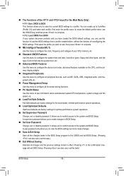
...voltages of your system becomes unstable and you have loaded the BIOS default settings, you to save the current BIOS settings to the system and BIOS Setup. A user password only allows you to complete. F12: Load CMOS from BIOS If your CPU, memory, etc. Standard CMOS... or disable password. First enter the profile name (to 8 profiles (Profile 1-8) and name each profile. Pressing to the confirmation message will exit BIOS Setup. (Pressing can create up to erase the default profile name, use this task.) Exit Without Saving Abandon all the changes made in...
...voltages of your system becomes unstable and you have loaded the BIOS default settings, you to save the current BIOS settings to the system and BIOS Setup. A user password only allows you to complete. F12: Load CMOS from BIOS If your CPU, memory, etc. Standard CMOS... or disable password. First enter the profile name (to 8 profiles (Profile 1-8) and name each profile. Pressing to the confirmation message will exit BIOS Setup. (Pressing can create up to erase the default profile name, use this task.) Exit Without Saving Abandon all the changes made in...
Manual
Page 37
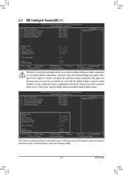
...Settings } Miscellaneous Settings [Press Enter] [Press Enter] [Press Enter] [Press Enter] [Press Enter] Item Help Menu Level BIOS Version BCLK CPU Frequency Memory Frequency Total Memory Size E3 99.80 MHz 3193.86 MHz 1330.65 MHz 1024 MB CPU Temperature 35.0... } Miscellaneous Settings [Press Enter] [Press Enter] [Press Enter] [Press Enter] [Press Enter] Item Help Menu Level BIOS Version BCLK CPU Frequency Memory Frequency Total Memory Size E3 99.80 MHz 3193.86 MHz 1330.65 MHz 1024 MB CPU Temperature 35.0...
...Settings } Miscellaneous Settings [Press Enter] [Press Enter] [Press Enter] [Press Enter] [Press Enter] Item Help Menu Level BIOS Version BCLK CPU Frequency Memory Frequency Total Memory Size E3 99.80 MHz 3193.86 MHz 1330.65 MHz 1024 MB CPU Temperature 35.0... } Miscellaneous Settings [Press Enter] [Press Enter] [Press Enter] [Press Enter] [Press Enter] Item Help Menu Level BIOS Version BCLK CPU Frequency Memory Frequency Total Memory Size E3 99.80 MHz 3193.86 MHz 1330.65 MHz 1024 MB CPU Temperature 35.0...
Manual
Page 38
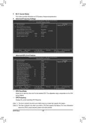
... is present only when you to alter the clock ratio for the installed CPU. Current Status This screen provides information on the CPU being installed. BIOS Setup - 38 - For more information about Intel CPUs' unique features, please visit Intel's website. The adjustable range is dependent on CPU/memory frequencies/parameters. } Advanced...
... is present only when you to alter the clock ratio for the installed CPU. Current Status This screen provides information on the CPU being installed. BIOS Setup - 38 - For more information about Intel CPUs' unique features, please visit Intel's website. The adjustable range is dependent on CPU/memory frequencies/parameters. } Advanced...


