
Manual
Page 1
...the steps below to the SATA disk. • Supported operating systems include Windows 7 and Windows Vista. • If you have and the BIOS version. - 1 - Launching the Intel Rapid Storage Technology utility to enable the Intel Smart Response Technology • The Intel Smart Response Technology ...is recommended that you have installed the operating system before enabling the Smart Response Technology. 1. Then save changes and exit BIOS Setup. The actual BIOS Setup menu options you will be lost once you enable RAID mode. Set PCH SATA Control Mode under the Integrated Peripherals...
...the steps below to the SATA disk. • Supported operating systems include Windows 7 and Windows Vista. • If you have and the BIOS version. - 1 - Launching the Intel Rapid Storage Technology utility to enable the Intel Smart Response Technology • The Intel Smart Response Technology ...is recommended that you have installed the operating system before enabling the Smart Response Technology. 1. Then save changes and exit BIOS Setup. The actual BIOS Setup menu options you will be lost once you enable RAID mode. Set PCH SATA Control Mode under the Integrated Peripherals...

Manual
Page 2
Installing the operating system and drivers to the SATA disk: After setting the BIOS, you can begin to open the Intel Rapid Storage Technology utility. - 2 - Launching the Intel Rapid Storage Technology utility to enable the Intel Smart Response Technology: ...
Installing the operating system and drivers to the SATA disk: After setting the BIOS, you can begin to open the Intel Rapid Storage Technology utility. - 2 - Launching the Intel Rapid Storage Technology utility to enable the Intel Smart Response Technology: ...
Manual
Page 3
...owners. For product-related information, check on our website at: http://www.gigabyte.com Identifying Your Motherboard Revision The revision number on your motherboard revision before updating motherboard BIOS, drivers, or when looking for technical information. The trademarks mentioned in ...this manual may be made by GIGABYTE without GIGABYTE's prior written permission. Changes to the specifications and features ...
...owners. For product-related information, check on our website at: http://www.gigabyte.com Identifying Your Motherboard Revision The revision number on your motherboard revision before updating motherboard BIOS, drivers, or when looking for technical information. The trademarks mentioned in ...this manual may be made by GIGABYTE without GIGABYTE's prior written permission. Changes to the specifications and features ...
Manual
Page 4
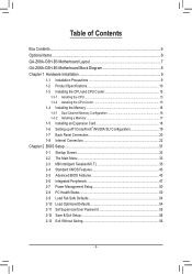
Table of Contents Box Contents...6 Optional Items...6 GA-Z68A-D3H-B3 Motherboard Layout 7 GA-Z68A-D3H-B3 Motherboard Block Diagram 8 Chapter 1 Hardware Installation 9 1-1 Installation Precautions 9 1-2 Product Specifications 10 1-3 Installing the CPU and CPU Cooler ... SLI Configuration 19 1-7 Back Panel Connectors 20 1-8 Internal Connectors 22 Chapter 2 BIOS Setup 31 2-1 Startup Screen 32 2-2 The Main Menu 33 2-3 MB Intelligent Tweaker(M.I.T 35 2-4 Standard CMOS Features 43 2-5 Advanced BIOS Features 45 2-6 Integrated Peripherals 47 2-7 Power Management Setup 50 2-8 PC Health ...
Table of Contents Box Contents...6 Optional Items...6 GA-Z68A-D3H-B3 Motherboard Layout 7 GA-Z68A-D3H-B3 Motherboard Block Diagram 8 Chapter 1 Hardware Installation 9 1-1 Installation Precautions 9 1-2 Product Specifications 10 1-3 Installing the CPU and CPU Cooler ... SLI Configuration 19 1-7 Back Panel Connectors 20 1-8 Internal Connectors 22 Chapter 2 BIOS Setup 31 2-1 Startup Screen 32 2-2 The Main Menu 33 2-3 MB Intelligent Tweaker(M.I.T 35 2-4 Standard CMOS Features 43 2-5 Advanced BIOS Features 45 2-6 Integrated Peripherals 47 2-7 Power Management Setup 50 2-8 PC Health ...
Manual
Page 5
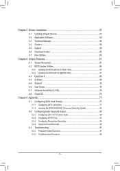
... 58 3-4 Contact...59 3-5 System...59 3-6 Download Center 60 3-7 New Utilities...60 Chapter 4 Unique Features 61 4-1 Xpress Recovery2 61 4-2 BIOS Update Utilities 64 4-2-1 Updating the BIOS with the Q-Flash Utility 64 4-2-2 Updating the BIOS with the @BIOS Utility 67 4-3 EasyTune 6...68 4-4 Q-Share...69 4-5 Smart 6™ ...70 4-6 Auto Green...74 4-7 eXtreme Hard Drive (X.H.D 75 4-8 Cloud OC...
... 58 3-4 Contact...59 3-5 System...59 3-6 Download Center 60 3-7 New Utilities...60 Chapter 4 Unique Features 61 4-1 Xpress Recovery2 61 4-2 BIOS Update Utilities 64 4-2-1 Updating the BIOS with the Q-Flash Utility 64 4-2-2 Updating the BIOS with the @BIOS Utility 67 4-3 EasyTune 6...68 4-4 Q-Share...69 4-5 Smart 6™ ...70 4-6 Auto Green...74 4-7 eXtreme Hard Drive (X.H.D 75 4-8 Cloud OC...
Manual
Page 8
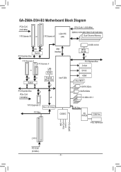
GA-Z68A-D3H-B3 Motherboard Block Diagram PCIe CLK (100 MHz) 1 PCI Express x16 or 2 PCI Express x8 LGA1155 CPU CPU CLK+/- (100 MHz) DDR3 2133/1866/1600/1333/... RTL8111E x1 Intel® Z68 PCI Express Bus x1 PCIe CLK (100 MHz) x1 2 USB 3.0/2.0 Etron EJ168 x1 PCI Express Bus D-Sub DVI-D HDMI Dual BIOS 4 SATA 3Gb/s 2 SATA 6Gb/s 12 USB 2.0/1.1 1 PCI Express x1 PCIe to PCI Bridge PCI Bus CODEC LPC Bus iTE IT8728 COM Port PS/2 KB/Mouse...
GA-Z68A-D3H-B3 Motherboard Block Diagram PCIe CLK (100 MHz) 1 PCI Express x16 or 2 PCI Express x8 LGA1155 CPU CPU CLK+/- (100 MHz) DDR3 2133/1866/1600/1333/... RTL8111E x1 Intel® Z68 PCI Express Bus x1 PCIe CLK (100 MHz) x1 2 USB 3.0/2.0 Etron EJ168 x1 PCI Express Bus D-Sub DVI-D HDMI Dual BIOS 4 SATA 3Gb/s 2 SATA 6Gb/s 12 USB 2.0/1.1 1 PCI Express x1 PCIe to PCI Bridge PCI Bus CODEC LPC Bus iTE IT8728 COM Port PS/2 KB/Mouse...
Manual
Page 12
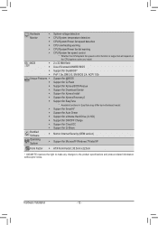
... 32 Mbit flash ŠŠ Use of licensed AWARD BIOS ŠŠ Support for DualBIOS™ ŠŠ PnP 1.0a, DMI 2.0, SM BIOS 2.4, ACPI 1.0b Unique Features ŠŠ Support for @BIOS ŠŠ Support for Q-Flash ŠŠ Support for Xpress BIOS Rescue ŠŠ Support for Download Center ŠŠ... System ŠŠ Support for Microsoft® Windows 7/Vista/XP Form Factor ŠŠ ATX Form Factor; 30.5cm x 22.5cm * GIGABYTE reserves the right to make any changes to the product specifications and product-related information without prior notice.
... 32 Mbit flash ŠŠ Use of licensed AWARD BIOS ŠŠ Support for DualBIOS™ ŠŠ PnP 1.0a, DMI 2.0, SM BIOS 2.4, ACPI 1.0b Unique Features ŠŠ Support for @BIOS ŠŠ Support for Q-Flash ŠŠ Support for Xpress BIOS Rescue ŠŠ Support for Download Center ŠŠ... System ŠŠ Support for Microsoft® Windows 7/Vista/XP Form Factor ŠŠ ATX Form Factor; 30.5cm x 22.5cm * GIGABYTE reserves the right to make any changes to the product specifications and product-related information without prior notice.
Manual
Page 16
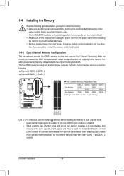
... a foolproof design. Hardware Installation - 16 - Dual Channel mode cannot be installed in only one DDR3 memory module is installed, the BIOS will double the original memory bandwidth. 1-4 Installing the Memory Read the following guidelines before you begin to install the memory: ••...DDR3_1, DDR3_3 Dual Channel Memory Configurations Table Two Modules Four Modules DDR3_4 DS/SS - The four DDR3 memory sockets are unable to GIGABYTE's website for optimum performance. For optimum performance, when enabling Dual Channel mode with two or four memory modules, it is recommended ...
... a foolproof design. Hardware Installation - 16 - Dual Channel mode cannot be installed in only one DDR3 memory module is installed, the BIOS will double the original memory bandwidth. 1-4 Installing the Memory Read the following guidelines before you begin to install the memory: ••...DDR3_1, DDR3_3 Dual Channel Memory Configurations Table Two Modules Four Modules DDR3_4 DS/SS - The four DDR3 memory sockets are unable to GIGABYTE's website for optimum performance. For optimum performance, when enabling Dual Channel mode with two or four memory modules, it is recommended ...
Manual
Page 18
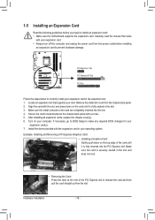
... Card: Gently push down on the card until it is fully inserted into the slot. 444 Secure the card's metal bracket to make any required BIOS changes for your operating system. Make sure the card is securely seated in the slot and does not rock. • Removing the Card: Press...into the PCI Express slot. Remove the metal slot cover from the power outlet before you begin to prevent hardware damage. If necessary, go to BIOS Setup to the chassis back panel with the slot, and press down on your card. Carefully read the manual that supports your computer. Hardware ...
... Card: Gently push down on the card until it is fully inserted into the slot. 444 Secure the card's metal bracket to make any required BIOS changes for your operating system. Make sure the card is securely seated in the slot and does not rock. • Removing the Card: Press...into the PCI Express slot. Remove the metal slot cover from the power outlet before you begin to prevent hardware damage. If necessary, go to BIOS Setup to the chassis back panel with the slot, and press down on your card. Carefully read the manual that supports your computer. Hardware ...
Manual
Page 21
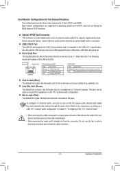
... USB 3.0 port supports the USB 3.0 specification and is occurring Line In Jack (Blue) The default line in operating system environment only, but not during the BIOS Setup or POST process. Line Out Jack (Green) The default line out jack. Do not rock it straight out from the motherboard. • When removing...
... USB 3.0 port supports the USB 3.0 specification and is occurring Line In Jack (Blue) The default line in operating system environment only, but not during the BIOS Setup or POST process. Line Out Jack (Green) The default line out jack. Do not rock it straight out from the motherboard. • When removing...
Manual
Page 24
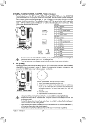
... with fan speed control design. Do not place a jumper cap on the headers. 6) BAT (Battery) The battery provides power to keep the values (such as BIOS configurations, date, and time information) in the correct orientation (the black connector wire is recommended that a system fan be handled in damage to the CPU...
... with fan speed control design. Do not place a jumper cap on the headers. 6) BAT (Battery) The battery provides power to keep the values (such as BIOS configurations, date, and time information) in the correct orientation (the black connector wire is recommended that a system fan be handled in damage to the CPU...
Manual
Page 26
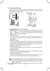
...system is in different patterns to the speaker on the chassis front panel. When connecting your system using the power switch (refer to Chapter 2, "BIOS Setup," "Power Management Setup," for information about beep codes. •• HD (Hard Drive Activity LED, Blue) Connects to the pin assignments...indicator on the chassis that can detect if the chassis cover has been removed. The LED is off when the system is detected, the BIOS may issue beeps in S1 sleep state. The system reports system startup status by chassis. This function requires a chassis with a chassis intrusion ...
...system is in different patterns to the speaker on the chassis front panel. When connecting your system using the power switch (refer to Chapter 2, "BIOS Setup," "Power Management Setup," for information about beep codes. •• HD (Hard Drive Activity LED, Blue) Connects to the pin assignments...indicator on the chassis that can detect if the chassis cover has been removed. The LED is off when the system is detected, the BIOS may issue beeps in S1 sleep state. The system reports system startup status by chassis. This function requires a chassis with a chassis intrusion ...
Manual
Page 27
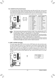
...-D2) 10 2 3 MIC2_R 4 -ACZ_DET 3 MIC Power 4 NC 5 LINE2_R 5 Line Out (R) 6 GND 6 NC 7 FAUDIO_JD 7 NC 8 No Pin 8 No Pin 9 LINE2_L 9 Line Out (L) 10 GND 10 NC BIOS Switcher (X58A-OC) DB_POR••T The front panel audio header supports HD audio by expansion cards) for digital audio output from your graphics card...
...-D2) 10 2 3 MIC2_R 4 -ACZ_DET 3 MIC Power 4 NC 5 LINE2_R 5 Line Out (R) 6 GND 6 NC 7 FAUDIO_JD 7 NC 8 No Pin 8 No Pin 9 LINE2_L 9 Line Out (L) 10 GND 10 NC BIOS Switcher (X58A-OC) DB_POR••T The front panel audio header supports HD audio by expansion cards) for digital audio output from your graphics card...
Manual
Page 29
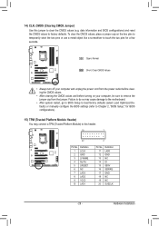
... CMOS values and before turning on the two pins to temporarily short the two pins or use a metal object like a screwdriver to Chapter 2, "BIOS Setup," for a few seconds. BIOS Switc 1 1 19 TPM w/housing 20 Pin No. 1 2 3 4 5 6 7 8 9 10 Definition LCLK GND LFRAME No Pin LRESET NC LAD3 LAD2 VCC3 LAD1...values (e.g. DB_PORT 15) TPM (Trusted Platform Module Header) You may cause damage to the motherboard. •• After system restart, go to BIOS Setup to factory defaults. Failure to do so may connect a TPM (Trusted Platform Module) to this jumper to remove the jumper cap from the...
... CMOS values and before turning on the two pins to temporarily short the two pins or use a metal object like a screwdriver to Chapter 2, "BIOS Setup," for a few seconds. BIOS Switc 1 1 19 TPM w/housing 20 Pin No. 1 2 3 4 5 6 7 8 9 10 Definition LCLK GND LFRAME No Pin LRESET NC LAD3 LAD2 VCC3 LAD1...values (e.g. DB_PORT 15) TPM (Trusted Platform Module Header) You may cause damage to the motherboard. •• After system restart, go to BIOS Setup to factory defaults. Failure to do so may connect a TPM (Trusted Platform Module) to this jumper to remove the jumper cap from the...
Manual
Page 31
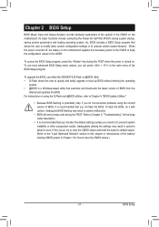
... the CMOS to keep the configuration values in the CMOS. To upgrade the BIOS, use either the GIGABYTE Q-Flash or @BIOS utility. • Q-Flash allows the user to quickly and easily upgrade or back up BIOS without entering the operating system. • @BIOS is recommended that you not alter the default settings (unless you need...
... the CMOS to keep the configuration values in the CMOS. To upgrade the BIOS, use either the GIGABYTE Q-Flash or @BIOS utility. • Q-Flash allows the user to quickly and easily upgrade or back up BIOS without entering the operating system. • @BIOS is recommended that you not alter the default settings (unless you need...
Manual
Page 32
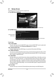
...on page 46. : BIOS SETUP\Q-FLASH Press the key to enter BIOS Setup or to access the Q-Flash utility in Boot Menu is effective for subsequent access to access the Q-Flash utility directly without entering BIOS Setup. A. BIOS Setup - 32 - Z68A-D3H-B3 E15 . . . . : BIOS Setup : XpressRecovery2 :... Boot Menu : Qflash 04/06/2011-Z68-7A89WG01C-00 Function Keys Function Keys: : POST SCREEN Press the key to show the BIOS POST screen at system startup,...
...on page 46. : BIOS SETUP\Q-FLASH Press the key to enter BIOS Setup or to access the Q-Flash utility in Boot Menu is effective for subsequent access to access the Q-Flash utility directly without entering BIOS Setup. A. BIOS Setup - 32 - Z68A-D3H-B3 E15 . . . . : BIOS Setup : XpressRecovery2 :... Boot Menu : Qflash 04/06/2011-Z68-7A89WG01C-00 Function Keys Function Keys: : POST SCREEN Press the key to show the BIOS POST screen at system startup,...
Manual
Page 33
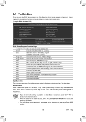
... Without Saving ESC: Quit F8: Q-Flash Select Item F10: Save & Exit Setup Change CPU's Clock & Voltage F11: Save CMOS to BIOS F12: Load CMOS from BIOS BIOS Setup Program Function Keys Move the selection bar to select an item Execute command or enter the submenu Main Menu: Exit the...settings for the current submenus Access the Q-Flash utility Display system information Save all the changes and exit the BIOS Setup program Save CMOS to BIOS Load CMOS from BIOS Main Menu Help The on-screen description of a highlighted setup option is in this chapter are for the ...
... Without Saving ESC: Quit F8: Q-Flash Select Item F10: Save & Exit Setup Change CPU's Clock & Voltage F11: Save CMOS to BIOS F12: Load CMOS from BIOS BIOS Setup Program Function Keys Move the selection bar to select an item Execute command or enter the submenu Main Menu: Exit the...settings for the current submenus Access the Q-Flash utility Display system information Save all the changes and exit the BIOS Setup program Save CMOS to BIOS Load CMOS from BIOS Main Menu Help The on-screen description of a highlighted setup option is in this chapter are for the ...
Manual
Page 34
... allows you to make changes. Save & Exit Setup Save all changes and the previous settings remain in effect. Pressing to load the BIOS settings from BIOS If your CPU, memory, etc. Standard CMOS Features Use this menu to configure the system time and date, hard drive types, and..., set , or disable password. First enter the profile name (to erase the default profile name, use this function to the confirmation message will exit BIOS Setup. (Pressing can use the SPACE key) and then press to complete. F12: Load CMOS from a profile created before, without the...
... allows you to make changes. Save & Exit Setup Save all changes and the previous settings remain in effect. Pressing to load the BIOS settings from BIOS If your CPU, memory, etc. Standard CMOS Features Use this menu to configure the system time and date, hard drive types, and..., set , or disable password. First enter the profile name (to erase the default profile name, use this function to the confirmation message will exit BIOS Setup. (Pressing can use the SPACE key) and then press to complete. F12: Load CMOS from a profile created before, without the...

Manual
Page 35
...Miscellaneous Settings [Press Enter] [Press Enter] [Press Enter] [Press Enter] [Press Enter] Item Help Menu Level BIOS Version BCLK CPU Frequency Memory Frequency Total Memory Size CPU Temperature Vcore DRAM Voltage E15 99.80 MHz 3193.85 MHz 1330.... Settings [Press Enter] [Press Enter] [Press Enter] [Press Enter] [Press Enter] Item Help Menu Level BIOS Version BCLK CPU Frequency Memory Frequency Total Memory Size CPU Temperature Vcore DRAM Voltage E15 99.80 MHz 3193.85 MHz 1330....
...Miscellaneous Settings [Press Enter] [Press Enter] [Press Enter] [Press Enter] [Press Enter] Item Help Menu Level BIOS Version BCLK CPU Frequency Memory Frequency Total Memory Size CPU Temperature Vcore DRAM Voltage E15 99.80 MHz 3193.85 MHz 1330.... Settings [Press Enter] [Press Enter] [Press Enter] [Press Enter] [Press Enter] Item Help Menu Level BIOS Version BCLK CPU Frequency Memory Frequency Total Memory Size CPU Temperature Vcore DRAM Voltage E15 99.80 MHz 3193.85 MHz 1330....
Manual
Page 36
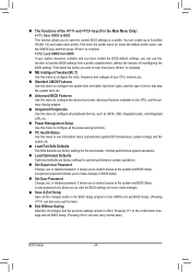
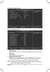
... allows CPU PLL voltage to operate at default value. For more information about Intel CPUs' unique features, please visit Intel's website. BIOS Setup - 36 - CPU Frequency Displays the current operating CPU frequency. Internal CPU PLL Overvoltage Enabled allows CPU PLL voltage to operate ...at a higher value. Auto lets the BIOS automatically configure this setting. (Default: Auto) (Note 1) This item is present only when you install a memory module that supports this ...
... allows CPU PLL voltage to operate at default value. For more information about Intel CPUs' unique features, please visit Intel's website. BIOS Setup - 36 - CPU Frequency Displays the current operating CPU frequency. Internal CPU PLL Overvoltage Enabled allows CPU PLL voltage to operate ...at a higher value. Auto lets the BIOS automatically configure this setting. (Default: Auto) (Note 1) This item is present only when you install a memory module that supports this ...


