User Manual
Page 3
... Classifications In order to their respective owners. For product-related information, check on our website at: http://www.gigabyte.com Identifying Your Motherboard Revision The revision number on your motherboard revision before updating motherboard BIOS, drivers, or when looking for technical information. The trademarks mentioned in this manual are legally registered to...
... Classifications In order to their respective owners. For product-related information, check on our website at: http://www.gigabyte.com Identifying Your Motherboard Revision The revision number on your motherboard revision before updating motherboard BIOS, drivers, or when looking for technical information. The trademarks mentioned in this manual are legally registered to...

User Manual
Page 4
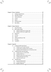
Table of Contents Box Contents...6 Optional Items...6 GA-X79-UD3 Motherboard Layout 7 GA-X79-UD3 Motherboard Block Diagram 8 Chapter 1 Hardware Installation 9 1-1 Installation Precautions 9 1-2 Product Specifications 10 1-3 Installing the CPU and CPU Cooler 13 ...Card 18 1-6 Setting up AMD CrossFireX™/NVIDIA SLI Configuration 19 1-7 Back Panel Connectors 20 1-8 Internal Connectors 22 Chapter 2 BIOS Setup 33 2-1 Startup Screen 34 2-2 The Main Menu 35 2-3 M.I.T...37 2-4 System...50 2-5 BIOS Features 51 2-6 Peripherals...53 2-7 Power Management 56 2-8 Save & Exit Setup 58 - 4 -
Table of Contents Box Contents...6 Optional Items...6 GA-X79-UD3 Motherboard Layout 7 GA-X79-UD3 Motherboard Block Diagram 8 Chapter 1 Hardware Installation 9 1-1 Installation Precautions 9 1-2 Product Specifications 10 1-3 Installing the CPU and CPU Cooler 13 ...Card 18 1-6 Setting up AMD CrossFireX™/NVIDIA SLI Configuration 19 1-7 Back Panel Connectors 20 1-8 Internal Connectors 22 Chapter 2 BIOS Setup 33 2-1 Startup Screen 34 2-2 The Main Menu 35 2-3 M.I.T...37 2-4 System...50 2-5 BIOS Features 51 2-6 Peripherals...53 2-7 Power Management 56 2-8 Save & Exit Setup 58 - 4 -
User Manual
Page 5
...Center 62 3-7 New Utilities...62 Chapter 4 Unique Features 63 4-1 Xpress Recovery2 63 4-2 BIOS Update Utilities 66 4-2-1 Updating the BIOS with the Q-Flash Utility 66 4-2-2 Updating the BIOS with the @BIOS Utility 69 4-3 EasyTune 6...70 4-4 Q-Share...71 4-5 Smart 6™ ...72 4-6 ...eXtreme Hard Drive (X.H.D 76 4-7 Cloud OC...77 4-8 TouchBIOS...78 Chapter 5 Appendix...79 5-1 Configuring SATA Hard Drive(s 79 5-1-1 Configuring Intel X79...
...Center 62 3-7 New Utilities...62 Chapter 4 Unique Features 63 4-1 Xpress Recovery2 63 4-2 BIOS Update Utilities 66 4-2-1 Updating the BIOS with the Q-Flash Utility 66 4-2-2 Updating the BIOS with the @BIOS Utility 69 4-3 EasyTune 6...70 4-4 Q-Share...71 4-5 Smart 6™ ...72 4-6 ...eXtreme Hard Drive (X.H.D 76 4-7 Cloud OC...77 4-8 TouchBIOS...78 Chapter 5 Appendix...79 5-1 Configuring SATA Hard Drive(s 79 5-1-1 Configuring Intel X79...

User Manual
Page 8
GA-X79-UD3 Motherboard Block Diagram 1 PCI Express x16 2 PCI Express x8 1 PCI 1 PCI Express x16 Express x8 or LGA2011 CPU CPU CLK+/- (100 MHz) DDR3 2133/1866/... x1 x1 x1 DMI 2.0 PCI Express Bus PCIe CLK (100 MHz) x1 x1 Marvell Marvell 88SE9172 88SE9172 x1 Marvell 88SE9172 Intel® X79 2 SATA 6Gb/s 2 SATA 6Gb/s 2 SATA 6Gb/s Dual BIOS 4 SATA 3Gb/s 2 SATA 6Gb/s 14 USB 2.0/1.1 PCI Express Bus PCI Bus PCI Bus LPC Bus IT8728 CODEC COM PS/2 KB/Mouse...
GA-X79-UD3 Motherboard Block Diagram 1 PCI Express x16 2 PCI Express x8 1 PCI 1 PCI Express x16 Express x8 or LGA2011 CPU CPU CLK+/- (100 MHz) DDR3 2133/1866/... x1 x1 x1 DMI 2.0 PCI Express Bus PCIe CLK (100 MHz) x1 x1 Marvell Marvell 88SE9172 88SE9172 x1 Marvell 88SE9172 Intel® X79 2 SATA 6Gb/s 2 SATA 6Gb/s 2 SATA 6Gb/s Dual BIOS 4 SATA 3Gb/s 2 SATA 6Gb/s 14 USB 2.0/1.1 PCI Express Bus PCI Bus PCI Bus LPC Bus IT8728 CODEC COM PS/2 KB/Mouse...
User Manual
Page 12
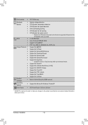
... Mbit flash ŠŠ Use of licensed AMI EFI BIOS ŠŠ Support for DualBIOS™ ŠŠ PnP 1.0a, DMI 2.0, SM BIOS 2.6, ACPI 2.0a Unique Features ŠŠ Support for @BIOS ŠŠ Support for Q-Flash ŠŠ Support for Xpress BIOS Rescue ŠŠ Support for Download Center ŠŠ... System ŠŠ Support for Microsoft® Windows 7/Vista/XP Form Factor ŠŠ ATX Form Factor; 30.5cm x 24.4cm * GIGABYTE reserves the right to make any changes to the product specifications and product-related information without prior notice.
... Mbit flash ŠŠ Use of licensed AMI EFI BIOS ŠŠ Support for DualBIOS™ ŠŠ PnP 1.0a, DMI 2.0, SM BIOS 2.6, ACPI 2.0a Unique Features ŠŠ Support for @BIOS ŠŠ Support for Q-Flash ŠŠ Support for Xpress BIOS Rescue ŠŠ Support for Download Center ŠŠ... System ŠŠ Support for Microsoft® Windows 7/Vista/XP Form Factor ŠŠ ATX Form Factor; 30.5cm x 24.4cm * GIGABYTE reserves the right to make any changes to the product specifications and product-related information without prior notice.
User Manual
Page 16
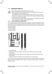
...: To enable four Channel mode, install four memory modules in the four memory sockets. Hardware Installation - 16 - It is installed, the BIOS will automatically detect the specifications and capacity of the memory. For optimum performance, when installing one direction. When installing two memory modules, we ...recommend that you install it in the DDR3_1 and DDR3_2 sockets. A memory module can be used. (Go to GIGABYTE's website for the latest supported memory speeds and memory modules.) •• Always turn off the computer and unplug the power cord ...
...: To enable four Channel mode, install four memory modules in the four memory sockets. Hardware Installation - 16 - It is installed, the BIOS will automatically detect the specifications and capacity of the memory. For optimum performance, when installing one direction. When installing two memory modules, we ...recommend that you install it in the DDR3_1 and DDR3_2 sockets. A memory module can be used. (Go to GIGABYTE's website for the latest supported memory speeds and memory modules.) •• Always turn off the computer and unplug the power cord ...

User Manual
Page 18
1-5 Installing an Expansion Card Read the following guidelines before installing an expansion card to prevent hardware damage. If necessary, go to BIOS Setup to make any required BIOS changes for your computer. Make sure the card is securely seated in the slot and does not rock. •• Removing the Card: Press the...
1-5 Installing an Expansion Card Read the following guidelines before installing an expansion card to prevent hardware damage. If necessary, go to BIOS Setup to make any required BIOS changes for your computer. Make sure the card is securely seated in the slot and does not rock. •• Removing the Card: Press the...

User Manual
Page 27
...load factory defaults (select Load Optimized Defaults) or manually configure the BIOS settings (refer to clear the CMOS values (e.g. date information and BIOS configurations) and reset the CMOS values to keep the values (such as BIOS configurations, date, and time information) in the power cord and ...in the CMOS when the computer is replaced with local environmental regulations. 10) CLR_CMOS (Clearing CMOS Jumper) Use this jumper to Chapter 2, "BIOS Setup," for a few seconds. To clear the CMOS values, use a metal object like a screwdriver to touch the positive and negative terminals...
...load factory defaults (select Load Optimized Defaults) or manually configure the BIOS settings (refer to clear the CMOS values (e.g. date information and BIOS configurations) and reset the CMOS values to keep the values (such as BIOS configurations, date, and time information) in the power cord and ...in the CMOS when the computer is replaced with local environmental regulations. 10) CLR_CMOS (Clearing CMOS Jumper) Use this jumper to Chapter 2, "BIOS Setup," for a few seconds. To clear the CMOS values, use a metal object like a screwdriver to touch the positive and negative terminals...

User Manual
Page 28
... LED on the chassis front panel. The system reports system startup status by chassis. When connecting your system using the power switch (refer to Chapter 2, "BIOS Setup," "Power Management Setup," for more information). •• SPEAK (Speaker, Orange): Connects to the speaker on the chassis front panel. 11) F_PANEL (Front Panel...
... LED on the chassis front panel. The system reports system startup status by chassis. When connecting your system using the power switch (refer to Chapter 2, "BIOS Setup," "Power Management Setup," for more information). •• SPEAK (Speaker, Orange): Connects to the speaker on the chassis front panel. 11) F_PANEL (Front Panel...

User Manual
Page 29
...7 FAUDIO_JD 7 NC 8 No Pin 8 No Pin 9 LINE2_L 9 Line Out (L) 10 GND 10 NC F_PANEL (H61M-D2) DIP 1 23 1 DIP 1 23 1 DIP 1 23 1 BIOS Switcher (X58A-OC) DB_PORT •• The front panel audio header supports HD audio by expansionPcCaIerdposw)efrocrodnnigecittaorl(aSuATdAio)(Xo5u8Atp-OuCt)from the HDMI display at... supports digital S/PDIF Out an1d2 3connects a S/PDIF digital audio cable (provided by default. Pin No. Definition 1 SPDIFO 1 2 GND ACPI_CPT (GA-IVB) SMB_CPT (GA-IVB) CLR_CMOS CI DIS_ME GP15_CPT (GA-IVB) XDP_CPU XDP_PCH (GA-IVB) - 29 - Hardware Installation
...7 FAUDIO_JD 7 NC 8 No Pin 8 No Pin 9 LINE2_L 9 Line Out (L) 10 GND 10 NC F_PANEL (H61M-D2) DIP 1 23 1 DIP 1 23 1 DIP 1 23 1 BIOS Switcher (X58A-OC) DB_PORT •• The front panel audio header supports HD audio by expansionPcCaIerdposw)efrocrodnnigecittaorl(aSuATdAio)(Xo5u8Atp-OuCt)from the HDMI display at... supports digital S/PDIF Out an1d2 3connects a S/PDIF digital audio cable (provided by default. Pin No. Definition 1 SPDIFO 1 2 GND ACPI_CPT (GA-IVB) SMB_CPT (GA-IVB) CLR_CMOS CI DIS_ME GP15_CPT (GA-IVB) XDP_CPU XDP_PCH (GA-IVB) - 29 - Hardware Installation

User Manual
Page 31
Definition 1 LCLK 2 GND 3 LFRAME 4 No Pin 5 LRESET 6 NC 7 LAD3 8 LAD2 9 VCC3 10 LAD1 BIO DB_PORT 1 Voltage measurement module(X58A-OC) P 2 Pin No. For purchasing the optional COM port cable, please contact the local dealer. 9 10 F_USB30 Pin No. F_AUDIO(H) 9 ...
Definition 1 LCLK 2 GND 3 LFRAME 4 No Pin 5 LRESET 6 NC 7 LAD3 8 LAD2 9 VCC3 10 LAD1 BIO DB_PORT 1 Voltage measurement module(X58A-OC) P 2 Pin No. For purchasing the optional COM port cable, please contact the local dealer. 9 10 F_USB30 Pin No. F_AUDIO(H) 9 ...

User Manual
Page 33
... key during system startup, saving system parameters and loading operating system, etc. To upgrade the BIOS, use either the GIGABYTE Q-Flash or @BIOS utility. •• Q-Flash allows the user to clear the CMOS values.) - 33 - Inadequate BIOS flashing may result in the CMOS on the motherboard supplies the necessary power to the CMOS...
... key during system startup, saving system parameters and loading operating system, etc. To upgrade the BIOS, use either the GIGABYTE Q-Flash or @BIOS utility. •• Q-Flash allows the user to clear the CMOS values.) - 33 - Inadequate BIOS flashing may result in the CMOS on the motherboard supplies the necessary power to the CMOS...

User Manual
Page 34
...utility in Boot Menu is effective for one time only. Function Keys Function Keys: : POST SCREEN Press the key to accept. Note: The setting in BIOS Setup. : SYSTEM INFORMATION Press the key to display your system information. : BOOT MENU Boot Menu allows you to set the first boot device without ...having to access the Q-Flash utility directly without entering BIOS Setup. In Boot Menu, use the up arrow key or the down arrow key to select the first boot device, then press to skip the...
...utility in Boot Menu is effective for one time only. Function Keys Function Keys: : POST SCREEN Press the key to accept. Note: The setting in BIOS Setup. : SYSTEM INFORMATION Press the key to display your system information. : BOOT MENU Boot Menu allows you to set the first boot device without ...having to access the Q-Flash utility directly without entering BIOS Setup. In Boot Menu, use the up arrow key or the down arrow key to select the first boot device, then press to skip the...
User Manual
Page 35
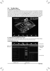
... Language Help Function Keys Configuration Items Current Settings - 35 - The Main Menu of the BIOS Setup Program On the main menu of the BIOS Setup Program.) B. The 3D BIOS Screen (Default) On GIGABYTE's uniquely designed 3D BIOS screen, you can use your mouse to select the item you want. (Sample... BIOS Version: F2a) Switch to the main menu of the BIOS Setup program, press arrow keys to...
... Language Help Function Keys Configuration Items Current Settings - 35 - The Main Menu of the BIOS Setup Program On the main menu of the BIOS Setup Program.) B. The 3D BIOS Screen (Default) On GIGABYTE's uniquely designed 3D BIOS screen, you can use your mouse to select the item you want. (Sample... BIOS Version: F2a) Switch to the main menu of the BIOS Setup program, press arrow keys to...

User Manual
Page 36
... is not stable as usual, load optimized defaults to set your system to its defaults. •• The BIOS Setup menus described in the BIOS Setup program to the CMOS and exit BIOS Setup. Or check the system/CPU temperatures, voltages, and fan speeds. „„ System Use this menu ...to configure the default language used by BIOS version. Use this menu to configure the device boot order, advanced features available on a menu Execute command or enter a menu / Increase the numeric ...
... is not stable as usual, load optimized defaults to set your system to its defaults. •• The BIOS Setup menus described in the BIOS Setup program to the CMOS and exit BIOS Setup. Or check the system/CPU temperatures, voltages, and fan speeds. „„ System Use this menu ...to configure the default language used by BIOS version. Use this menu to configure the device boot order, advanced features available on a menu Execute command or enter a menu / Increase the numeric ...
User Manual
Page 37
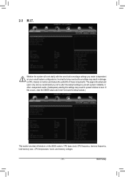
2-3 M.I.T. This page is dependent on the BIOS version, CPU base clock, CPU frequency, memory frequency, total memory size , CPU temperature, Vcore, and memory voltages. - 37 - Incorrectly doing overclock/overvoltage may result in ... not to alter the default settings to prevent system instability or other unexpected results. (Inadequately altering the settings may result in system's failure to boot. BIOS Setup
2-3 M.I.T. This page is dependent on the BIOS version, CPU base clock, CPU frequency, memory frequency, total memory size , CPU temperature, Vcore, and memory voltages. - 37 - Incorrectly doing overclock/overvoltage may result in ... not to alter the default settings to prevent system instability or other unexpected results. (Inadequately altering the settings may result in system's failure to boot. BIOS Setup

User Manual
Page 38
... to default values. (Default: Disabled) && Host Clock Frequency Allows you change the Processor Base Clock setting, the Memory Frequency (Mhz) setting below will be configurable. BIOS Setup - 38 - This item is configurable only when BCLK/PCIe Clock Control is highly recommended that the frequency be changed synchronously. `` M.I.T. Important: It is enabled...
... to default values. (Default: Disabled) && Host Clock Frequency Allows you change the Processor Base Clock setting, the Memory Frequency (Mhz) setting below will be configurable. BIOS Setup - 38 - This item is configurable only when BCLK/PCIe Clock Control is highly recommended that the frequency be changed synchronously. `` M.I.T. Important: It is enabled...

User Manual
Page 39
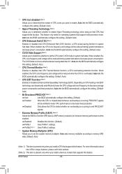
... to set the CPU Turbo ratios for CPU Turbo mode. For more information about Intel CPUs' unique features, please visit Intel's website. - 39 - BIOS Setup Auto lets the BIOS automatically configure this setting. (Default: Auto) && Turbo Ratio (1-Core Active)~(6-Core Active) (Note) Allows you to reduce the current. When the CPU power... Limit (Watts) Allows you to operate at a higher value. Disabled allows CPU PLL voltage to set a power limit for CPU Turbo mode. Auto lets the BIOS automatically configure this feature.
... to set the CPU Turbo ratios for CPU Turbo mode. For more information about Intel CPUs' unique features, please visit Intel's website. - 39 - BIOS Setup Auto lets the BIOS automatically configure this setting. (Default: Auto) && Turbo Ratio (1-Core Active)~(6-Core Active) (Note) Allows you to reduce the current. When the CPU power... Limit (Watts) Allows you to operate at a higher value. Disabled allows CPU PLL voltage to set a power limit for CPU Turbo mode. Auto lets the BIOS automatically configure this feature.
User Manual
Page 40
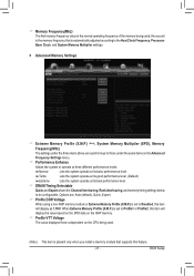
... (Note 2) Uses Profile 2 settings. && System Memory Multiplier (SPD) Allows you install a CPU that supports this feature. Auto lets the BIOS automatically configure this setting. (Default: Auto) && CPU EIST Function (Note 1) Enables or disables Enhanced Intel SpeedStep Technology (EIST). For more information...Intel EIST technology can dynamically and effectively lower the CPU voltage and core frequency to decrease power consumption. Auto lets the BIOS automatically configure this setting. (Default: Auto) && CPU Thermal Monitor (Note 1) Enables or disables Intel CPU Thermal Monitor ...
... (Note 2) Uses Profile 2 settings. && System Memory Multiplier (SPD) Allows you install a CPU that supports this feature. Auto lets the BIOS automatically configure this setting. (Default: Auto) && CPU EIST Function (Note 1) Enables or disables Enhanced Intel SpeedStep Technology (EIST). For more information...Intel EIST technology can dynamically and effectively lower the CPU voltage and core frequency to decrease power consumption. Auto lets the BIOS automatically configure this setting. (Default: Auto) && CPU Thermal Monitor (Note 1) Enables or disables Intel CPU Thermal Monitor ...
User Manual
Page 41
..., and memory timing settings below to be configurable. && Memory Frequency(Mhz) The first memory frequency value is set to Profile1 or Profile2, this feature. - 41 - BIOS Setup When Extreme Memory Profile (X.M.P.) is set to Disabled, this item will display the value based on the SPD data on the XMP memory. && Profile...
..., and memory timing settings below to be configurable. && Memory Frequency(Mhz) The first memory frequency value is set to Profile1 or Profile2, this feature. - 41 - BIOS Setup When Extreme Memory Profile (X.M.P.) is set to Disabled, this item will display the value based on the SPD data on the XMP memory. && Profile...


