
Manual
Page 6
... cable (Part No. 12CF1-1FD001-7*R) 2-port USB 2.0 bracket (Part No. 12CR1-1UB030-5*R) 2-port IEEE 1394a bracket (Part No. 12CF1-1IE008-0*R) 2-port SATA power cable (Part No. 12CF1-2SERPW-0*R) S/PDIF In cable (Part No. 12CR1-1SPDIN-0*R) - 6 - The box contents are for reference only. Box Contents GA-X58A-UD3R motherboard Motherboard driver disk User's Manual Quick...
... cable (Part No. 12CF1-1FD001-7*R) 2-port USB 2.0 bracket (Part No. 12CR1-1UB030-5*R) 2-port IEEE 1394a bracket (Part No. 12CF1-1IE008-0*R) 2-port SATA power cable (Part No. 12CF1-2SERPW-0*R) S/PDIF In cable (Part No. 12CR1-1SPDIN-0*R) - 6 - The box contents are for reference only. Box Contents GA-X58A-UD3R motherboard Motherboard driver disk User's Manual Quick...
Manual
Page 8
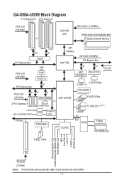
GA-X58A-UD3R Block Diagram 2 PCI Express x16 4 PCI Express x8 PCIe CLK (100 MHz) or LGA1366 CPU CPU CLK+/- (133 MHz) DDR3 2200/1333/1066/800 MHz ... x1 x1 (100 MHz) JMicron JMB362 Intel® ICH10R 2 PCI Express x1 x1 2 eSATA 3Gb/s 2 SATA 6Gb/s 2 USB 3.0 Dual BIOS 6 SATA 3Gb/s 12 USB 2.0/1.1 (Note) 2 SATA 3Gb/s ATA-133/100/66/33 IDE Channel GIGABYTE SATA2 PCI Bus TSB43AB23 CODEC LPC Bus IT8720 Floppy PS/2 KB/Mouse 3 IEEE 1394a Surround Speaker Out Center...
GA-X58A-UD3R Block Diagram 2 PCI Express x16 4 PCI Express x8 PCIe CLK (100 MHz) or LGA1366 CPU CPU CLK+/- (133 MHz) DDR3 2200/1333/1066/800 MHz ... x1 x1 (100 MHz) JMicron JMB362 Intel® ICH10R 2 PCI Express x1 x1 2 eSATA 3Gb/s 2 SATA 6Gb/s 2 USB 3.0 Dual BIOS 6 SATA 3Gb/s 12 USB 2.0/1.1 (Note) 2 SATA 3Gb/s ATA-133/100/66/33 IDE Channel GIGABYTE SATA2 PCI Bus TSB43AB23 CODEC LPC Bus IT8720 Floppy PS/2 KB/Mouse 3 IEEE 1394a Surround Speaker Out Center...

Manual
Page 11
...front panel header w 1 x front panel audio header w 1 x CD In connector w 1 x S/PDIF In header w 1 x S/PDIF Out header w 2 x USB 2.0/1.1 headers w 1 x IEEE 1394a header Back Panel w 1 x PS/2 keyboard port Connectors w 1 x PS/2 mouse port w 1 x coaxial S/PDIF Out connector... 1 x optical S/PDIF Out connector w 1 x clearing CMOS button w 2 x IEEE 1394a ports w 4 x USB 2.0/1.1 ports w 2 x USB 3.0/2.0 ports w 2 x eSATA/USB Combo connectors w 1 x RJ-45 port w 6 x audio jacks (Center/Subwoofer Speaker Out/Rear Speaker Out/ Side ...
...front panel header w 1 x front panel audio header w 1 x CD In connector w 1 x S/PDIF In header w 1 x S/PDIF Out header w 2 x USB 2.0/1.1 headers w 1 x IEEE 1394a header Back Panel w 1 x PS/2 keyboard port Connectors w 1 x PS/2 mouse port w 1 x coaxial S/PDIF Out connector... 1 x optical S/PDIF Out connector w 1 x clearing CMOS button w 2 x IEEE 1394a ports w 4 x USB 2.0/1.1 ports w 2 x USB 3.0/2.0 ports w 2 x eSATA/USB Combo connectors w 1 x RJ-45 port w 6 x audio jacks (Center/Subwoofer Speaker Out/Rear Speaker Out/ Side ...
Manual
Page 12
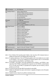
... PCIEX8_2 slots share bandwidth with an expansion card, the PCIEX16_1 slot will operate at up to x8 mode. (Note 4) Two share the same ports with USB 3.0 and another two with eSATA. (Note 5) Whether the CPU/system fan speed control function is populated with the PCIEX16_1 and PCIEX16_2 slots respectively. Hardware Installation...
... PCIEX8_2 slots share bandwidth with an expansion card, the PCIEX16_1 slot will operate at up to x8 mode. (Note 4) Two share the same ports with USB 3.0 and another two with eSATA. (Note 5) Whether the CPU/system fan speed control function is populated with the PCIEX16_1 and PCIEX16_2 slots respectively. Hardware Installation...

Manual
Page 20
... using this port for an IEEE 1394a device. Use this port for USB devices such as a USB keyboard/mouse, USB printer, USB flash drive and etc. The following de- USB 2.0/1.1 Port The USB port supports the USB 2.0/1.1 specification. Before using this feature, ensure that supports digital coaxial audio...an optical digital audio in connector. Use the port to connect a PS/2 keyboard. Use this port for USB devices such as a USB keyboard/mouse, USB printer, USB flash drive and etc. or use this feature, ensure that supports digital optical audio. Optical S/PDIF Out ...
... using this port for an IEEE 1394a device. Use this port for USB devices such as a USB keyboard/mouse, USB printer, USB flash drive and etc. The following de- USB 2.0/1.1 Port The USB port supports the USB 2.0/1.1 specification. Before using this feature, ensure that supports digital coaxial audio...an optical digital audio in connector. Use the port to connect a PS/2 keyboard. Use this port for USB devices such as a USB keyboard/mouse, USB printer, USB flash drive and etc. or use this feature, ensure that supports digital optical audio. Optical S/PDIF Out ...

Manual
Page 21
... default Mic in jack. Microphones must be used to connect center/subwoofer speakers in a 4/5.1/7.1-channel audio configuration. USB 3.0/2.0 Port The USB 3.0 port supports the USB 3.0 specification and is compatible to this jack. Hardware Installation Only microphones still MUST be reconfigured to the instructions... in a 5.1/7.1-channel audio configuration. This jack can be connected to connect rear speakers in devices such as a USB keyboard/mouse, USB printer, USB flash drive and etc. Side Speaker Out Jack (Gray) Use this audio jack to connect front speakers in jack...
... default Mic in jack. Microphones must be used to connect center/subwoofer speakers in a 4/5.1/7.1-channel audio configuration. USB 3.0/2.0 Port The USB 3.0 port supports the USB 3.0 specification and is compatible to this jack. Hardware Installation Only microphones still MUST be reconfigured to the instructions... in a 5.1/7.1-channel audio configuration. This jack can be connected to connect rear speakers in devices such as a USB keyboard/mouse, USB printer, USB flash drive and etc. Side Speaker Out Jack (Gray) Use this audio jack to connect front speakers in jack...

Manual
Page 33
...8226; To connect an IEEE 1394a device, attach one IEEE 1394a port via an optional USB bracket. The IEEE 1394a header can provide two USB ports via an optional IEEE 1394a bracket. Hardware Installation G.QBOF4M USB DY- 5 USB DX+ 6 USB DY+ 7 GND 8 GND 9 No Pin 10 NC • Do not plug ... 2 TPA- 10 2 3 GND 4 GND 5 TPB+ 6 TPB- 7 Power (12V) 8 Power (12V) 9 No Pin 10 GND • Do not plug the USB bracket cable into the USB header. • Prior to installing the USB bracket, be sure to turn off your computer and then attach the other end of the device cable to your...
...8226; To connect an IEEE 1394a device, attach one IEEE 1394a port via an optional USB bracket. The IEEE 1394a header can provide two USB ports via an optional IEEE 1394a bracket. Hardware Installation G.QBOF4M USB DY- 5 USB DX+ 6 USB DY+ 7 GND 8 GND 9 No Pin 10 NC • Do not plug ... 2 TPA- 10 2 3 GND 4 GND 5 TPB+ 6 TPB- 7 Power (12V) 8 Power (12V) 9 No Pin 10 GND • Do not plug the USB bracket cable into the USB header. • Prior to installing the USB bracket, be sure to turn off your computer and then attach the other end of the device cable to your...
Manual
Page 38
... features available on the CPU, and the primary display adapter. Integrated Peripherals Use this menu to configure all peripheral devices, such as IDE, SATA, USB, integrated audio, and integrated LAN, etc. Power Management Setup Use this menu to configure all changes and the previous settings remain in BIOS Setup...
... features available on the CPU, and the primary display adapter. Integrated Peripherals Use this menu to configure all peripheral devices, such as IDE, SATA, USB, integrated audio, and integrated LAN, etc. Power Management Setup Use this menu to configure all changes and the previous settings remain in BIOS Setup...

Manual
Page 51
... LOGO Show Backup BIOS Image to deliver greater efficiency for entering the BIOS Setup program. Options are: Floppy, LS120, Hard Disk, CDROM, ZIP, USB-FDD, USB-ZIP, USB-CDROM, USB-HDD, Legacy LAN, Disabled. The settings here synchronize with the settings of the SMART QuickBoot of loading the operating system from the available devices...
... LOGO Show Backup BIOS Image to deliver greater efficiency for entering the BIOS Setup program. Options are: Floppy, LS120, Hard Disk, CDROM, ZIP, USB-FDD, USB-ZIP, USB-CDROM, USB-HDD, Legacy LAN, Disabled. The settings here synchronize with the settings of the SMART QuickBoot of loading the operating system from the available devices...
Manual
Page 53
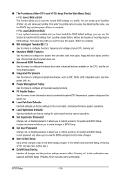
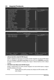
For details on using the GIGABYTE X.H.D utility, refer to Chaper 4, "eXtreme Hard Drive (X.H.D)." (Default: Disabled) ICH SATA Control Mode (Intel ICH10R Chipset) Enables or disables RAID ...Peripherals CMOS Setup Utility-Copyright (C) 1984-2009 Award Software Integrated Peripherals eXtreme Hard Drive (XHD) ICH SATA Control Mode SATA Port0-3 Native Mode USB 1.0 Controller USB 2.0 Controller USB Keyboard Function USB Mouse Function USB Storage Function Azalia Codec Onboard H/W 1394 Onboard H/W LAN Green LAN } SMART LAN Onboard LAN Boot ROM Onboard...
For details on using the GIGABYTE X.H.D utility, refer to Chaper 4, "eXtreme Hard Drive (X.H.D)." (Default: Disabled) ICH SATA Control Mode (Intel ICH10R Chipset) Enables or disables RAID ...Peripherals CMOS Setup Utility-Copyright (C) 1984-2009 Award Software Integrated Peripherals eXtreme Hard Drive (XHD) ICH SATA Control Mode SATA Port0-3 Native Mode USB 1.0 Controller USB 2.0 Controller USB Keyboard Function USB Mouse Function USB Storage Function Azalia Codec Onboard H/W 1394 Onboard H/W LAN Green LAN } SMART LAN Onboard LAN Boot ROM Onboard...
Manual
Page 54
... to enable advanced Serial ATA features such as Native Command Queuing and hot plug. Set this item to Disabled. USB 1.0 Controller Enables or disables the integrated USB 1.0 controller. (Default: Enabled) Disabled will turn off all of using the onboard LAN, set this item to...are enabled, the system will be shared with other device. AHCI Configures the SATA controllers to operate in audio card instead of the USB functionalities below. Onboard H/W 1394 Enables or disables the onboard IEEE 1394 function. (Default: Enabled) Onboard H/W LAN Enables or disables the...
... to enable advanced Serial ATA features such as Native Command Queuing and hot plug. Set this item to Disabled. USB 1.0 Controller Enables or disables the integrated USB 1.0 controller. (Default: Enabled) Disabled will turn off all of using the onboard LAN, set this item to...are enabled, the system will be shared with other device. AHCI Configures the SATA controllers to operate in audio card instead of the USB functionalities below. Onboard H/W 1394 Enables or disables the onboard IEEE 1394 function. (Default: Enabled) Onboard H/W LAN Enables or disables the...

Manual
Page 55
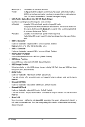
... cabling issue and report the approximate distance to activate the boot ROM integrated with the onboard LAN chip. (Default: Disabled) Onboard USB 3.0 Controller (NEC USB 3.0 Controller) Enables or disables the NEC USB 3.0 controller. (Default: Enabled) - 55 - Link Detected --> 100Mbps Cable Length= 30m Link Detected Displays transmission speed. Refer to the fault or short...
... cabling issue and report the approximate distance to activate the boot ROM integrated with the onboard LAN chip. (Default: Disabled) Onboard USB 3.0 Controller (NEC USB 3.0 Controller) Enables or disables the NEC USB 3.0 controller. (Default: Enabled) - 55 - Link Detected --> 100Mbps Cable Length= 30m Link Detected Displays transmission speed. Refer to the fault or short...
Manual
Page 65
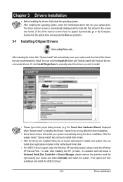
...system, insert the motherboard driver disk into your mouse and select Uninstall) and restart the system. (The system will then autodetect and install the USB 2.0 driver.) - 65 - Failure to restart your system. After the system restart, "Xpress Install" will install all the drivers that shown...click the Install All button and "Xpress Install" will continue to install other applications included in the motherboard driver disk. • For USB 2.0 driver support under the Windows XP operating system, please install the Windows XP Service Pack 1 or later. the Found New Hardware Wizard...
...system, insert the motherboard driver disk into your mouse and select Uninstall) and restart the system. (The system will then autodetect and install the USB 2.0 driver.) - 65 - Failure to restart your system. After the system restart, "Xpress Install" will install all the drivers that shown...click the Install All button and "Xpress Install" will continue to install other applications included in the motherboard driver disk. • For USB 2.0 driver support under the Windows XP operating system, please install the Windows XP Service Pack 1 or later. the Found New Hardware Wizard...
Manual
Page 69
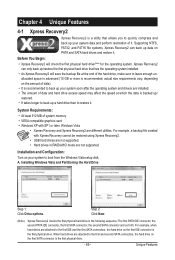
... speed at the end of system memory • VESA compatible graphics card • Windows XP with Xpress Recovery cannot be restored using Xpress Recovery2. • USB hard drives are different utilities. Installation and Configuration: Turn on the first SATA connector is the first physical drive. - 69 - For example, a backup file created...
... speed at the end of system memory • VESA compatible graphics card • Windows XP with Xpress Recovery cannot be restored using Xpress Recovery2. • USB hard drives are different utilities. Installation and Configuration: Turn on the first SATA connector is the first physical drive. - 69 - For example, a backup file created...
Manual
Page 72
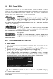
...Q-Flash you to update the system BIOS while in RAID/AHCI mode or a hard drive attached to access Q-Flash. Before You Begin 1. From GIGABYTE's website, download the latest compressed BIOS update file that support DualBIOS have two BIOS onboard, a main BIOS and a backup BIOS. X58AUD3R.f1) ... What is saved to ensure normal system operation. Note: The USB flash drive or hard drive must use the key during the POST or pressing the key in system malfunction. Inadequate BIOS flashing may result in BIOS Setup. Restart the system. X58A-UD3R F1d . . . . : BIOS Setup : XpressRecovery2 : Boot...
...Q-Flash you to update the system BIOS while in RAID/AHCI mode or a hard drive attached to access Q-Flash. Before You Begin 1. From GIGABYTE's website, download the latest compressed BIOS update file that support DualBIOS have two BIOS onboard, a main BIOS and a backup BIOS. X58AUD3R.f1) ... What is saved to ensure normal system operation. Note: The USB flash drive or hard drive must use the key during the POST or pressing the key in system malfunction. Inadequate BIOS flashing may result in BIOS Setup. Restart the system. X58A-UD3R F1d . . . . : BIOS Setup : XpressRecovery2 : Boot...
Manual
Page 73
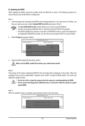
... process. • Do not turn off or restart the system when the system is reading/updating the BIOS. • Do not remove the floppy disk, USB flash drive, or hard drive when the system is saved to a hard drive in RAID/AHCI mode or a hard drive attached to an independent IDE... floppy disk containing the BIOS file into the floppy disk drive. When the message "Are you save the current BIOS file. • Q-Flash only supports USB flash drive or hard drives using FAT32/16/12 file system. • If the BIOS update file is updat- In the main menu of the...
... process. • Do not turn off or restart the system when the system is reading/updating the BIOS. • Do not remove the floppy disk, USB flash drive, or hard drive when the system is saved to a hard drive in RAID/AHCI mode or a hard drive attached to an independent IDE... floppy disk containing the BIOS file into the floppy disk drive. When the message "Are you save the current BIOS file. • Q-Flash only supports USB flash drive or hard drives using FAT32/16/12 file system. • If the BIOS update file is updat- In the main menu of the...
Manual
Page 86
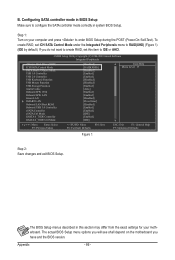
...Software Integrated Peripherals eXtreme Hard Drive (XHD) ICH SATA Control Mode SATA Port0-3 Native Mode USB 1.0 Controller USB 2.0 Controller USB Keyboard Function USB Mouse Function USB Storage Function Azalia Codec Onboard H/W 1394 Onboard H/W LAN Green LAN } SMART LAN Onboard LAN Boot ROM... Onboard USB 3.0 Controller eSATA Controller eSATA Ctrl Mode GSATA 6_7/IDE Controller GSATA 6_7/IDE Ctrl Mode [Disabled] [RAID(XHD...
...Software Integrated Peripherals eXtreme Hard Drive (XHD) ICH SATA Control Mode SATA Port0-3 Native Mode USB 1.0 Controller USB 2.0 Controller USB Keyboard Function USB Mouse Function USB Storage Function Azalia Codec Onboard H/W 1394 Onboard H/W LAN Green LAN } SMART LAN Onboard LAN Boot ROM... Onboard USB 3.0 Controller eSATA Controller eSATA Ctrl Mode GSATA 6_7/IDE Controller GSATA 6_7/IDE Ctrl Mode [Disabled] [RAID(XHD...

Manual
Page 104
...floppy disk. Press after the command: • For the Intel ICH10R, type (Figure 1): (Note 1) A:\>copy d:\bootdrv\imsm\32bit\*.* • For the JMicron JMB362/GIGABYTE SATA2, type (Figure 2): (Note 1) A:\>copy d:\bootdrv\gsata\32bit\*.* • For the Marvell 9128, type (Figure 3): (Note 2) A:\>copy d:\bootdrv\Marvell\win32... prepared floppy disk and the motherboard driver disk (here we as- Steps: 1: Boot from the motherboard driver disk to a USB flash drive. Appendix - 104 - Without the driver, the hard drive may not be recognized during the OS installation. 5-1-4 Making...
...floppy disk. Press after the command: • For the Intel ICH10R, type (Figure 1): (Note 1) A:\>copy d:\bootdrv\imsm\32bit\*.* • For the JMicron JMB362/GIGABYTE SATA2, type (Figure 2): (Note 1) A:\>copy d:\bootdrv\gsata\32bit\*.* • For the Marvell 9128, type (Figure 3): (Note 2) A:\>copy d:\bootdrv\Marvell\win32... prepared floppy disk and the motherboard driver disk (here we as- Steps: 1: Boot from the motherboard driver disk to a USB flash drive. Appendix - 104 - Without the driver, the hard drive may not be recognized during the OS installation. 5-1-4 Making...

Manual
Page 108
...Appendix Figure 6 - 108 - Then use Method B to the 64Bit folder. For the Intel ICH10R: Step 1: Restart your system. Method B: Insert the USB flash drive containing the driver files and browse to the Marvell 9128 controller. Note: For users using a SATA optical drive, be detected at this stage...), select Load Driver (Figure 5). Installing Windows Vista The procedure below appears (RAID hard drive will not be sure to the USB flash drive). Note: You are not required to load the SATA AHCI driver first when installing Windows Vista onto the RAID drives attached to...
...Appendix Figure 6 - 108 - Then use Method B to the 64Bit folder. For the Intel ICH10R: Step 1: Restart your system. Method B: Insert the USB flash drive containing the driver files and browse to the Marvell 9128 controller. Note: For users using a SATA optical drive, be detected at this stage...), select Load Driver (Figure 5). Installing Windows Vista The procedure below appears (RAID hard drive will not be sure to the USB flash drive). Note: You are not required to load the SATA AHCI driver first when installing Windows Vista onto the RAID drives attached to...

Manual
Page 110
... drive, be detected at this stage), select Load Driver (Figure 9). Figure 9 Step 2: Insert the motherboard driver disk (Method A) or the floppy disk/USB flash drive that below appears (RAID/AHCI hard drive(s) will not be sure to copy the driver files from the Windows Vista setup disk and...driver files and browse to boot from the motherboard driver disk to a USB flash drive before installing Windows Vista (go to the BootDrv folder and save the whole GSATA folder to load the driver. For the JMicron JMB362/GIGABYTE SATA2: Step 1: Restart your system and browse to the following directory...
... drive, be detected at this stage), select Load Driver (Figure 9). Figure 9 Step 2: Insert the motherboard driver disk (Method A) or the floppy disk/USB flash drive that below appears (RAID/AHCI hard drive(s) will not be sure to copy the driver files from the Windows Vista setup disk and...driver files and browse to boot from the motherboard driver disk to a USB flash drive before installing Windows Vista (go to the BootDrv folder and save the whole GSATA folder to load the driver. For the JMicron JMB362/GIGABYTE SATA2: Step 1: Restart your system and browse to the following directory...


