
Manual
Page 5
...Hard Drive (X.H.D 84 Chapter 5 Appendix...85 5-1 Configuring SATA Hard Drive(s 85 5-1-1 Configuring Intel ICH10R SATA Controllers 85 5-1-2 Configuring JMicron JMB362/GIGABYTE SATA2 SATA Controller 93 5-1-3 Configuring Marvell 9128 SATA Controller 99 5-1-4 Making a SATA RAID/AHCI Driver Diskette 104 5-1-5 Installing the SATA RAID... Enabling the Dolby Home Theater Function 123 5-2-4 Configuring Microphone Recording 124 5-2-5 Using the Sound Recorder 126 5-3 Troubleshooting 127 5-3-1 Frequently Asked Questions 127 5-3-2 Troubleshooting Procedure 128 5-4 Regulatory Statements 130 - 5 -
...Hard Drive (X.H.D 84 Chapter 5 Appendix...85 5-1 Configuring SATA Hard Drive(s 85 5-1-1 Configuring Intel ICH10R SATA Controllers 85 5-1-2 Configuring JMicron JMB362/GIGABYTE SATA2 SATA Controller 93 5-1-3 Configuring Marvell 9128 SATA Controller 99 5-1-4 Making a SATA RAID/AHCI Driver Diskette 104 5-1-5 Installing the SATA RAID... Enabling the Dolby Home Theater Function 123 5-2-4 Configuring Microphone Recording 124 5-2-5 Using the Sound Recorder 126 5-3 Troubleshooting 127 5-3-1 Frequently Asked Questions 127 5-3-2 Troubleshooting Procedure 128 5-4 Regulatory Statements 130 - 5 -

Manual
Page 30
.../PWR (Message/Power/Sleep LED, Yellow/Purple): System Status LED Connects to the hard drive activity LED on the chassis front panel. Refer to Chapter 5, "Troubleshooting," for more information). • SPEAK (Speaker, Orange): Connects to the speaker on the chassis front panel. This function requires a chassis with a chassis intrusion switch/sensor...
.../PWR (Message/Power/Sleep LED, Yellow/Purple): System Status LED Connects to the hard drive activity LED on the chassis front panel. Refer to Chapter 5, "Troubleshooting," for more information). • SPEAK (Speaker, Orange): Connects to the speaker on the chassis front panel. This function requires a chassis with a chassis intrusion switch/sensor...
Manual
Page 35
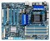
... is recommended that you not flash the BIOS. For instructions on . To upgrade the BIOS, use either the GIGABYTE Q-Flash or @BIOS utility. • Q-Flash allows the user to boot. Refer to Chapter 5, "Troubleshooting," for how to prevent system instability or other unexpected results. To see more advanced BIOS Setup menu options...
... is recommended that you not flash the BIOS. For instructions on . To upgrade the BIOS, use either the GIGABYTE Q-Flash or @BIOS utility. • Q-Flash allows the user to boot. Refer to Chapter 5, "Troubleshooting," for how to prevent system instability or other unexpected results. To see more advanced BIOS Setup menu options...

Manual
Page 127
... Wizard appears, click Cancel. Appendix For motherboards that have a clearing CMOS jumper, refer to the Support&Downloads\Motherboard\FAQ page on GIGABYTE's website. Q: In the BIOS Setup program, why are hidden in Device Manager or Sound, video, and game controllers. A: Some... driver from the motherboard driver disk or download the audio driver from GIGABYTE's website to the Support&Downloads\Motherboards\FAQ page on our website and search for "onboard HD audio driver." 5-3 Troubleshooting 5-3-1 Frequently Asked Questions To read more details, go to install. ...
... Wizard appears, click Cancel. Appendix For motherboards that have a clearing CMOS jumper, refer to the Support&Downloads\Motherboard\FAQ page on GIGABYTE's website. Q: In the BIOS Setup program, why are hidden in Device Manager or Sound, video, and game controllers. A: Some... driver from the motherboard driver disk or download the audio driver from GIGABYTE's website to the Support&Downloads\Motherboards\FAQ page on our website and search for "onboard HD audio driver." 5-3 Troubleshooting 5-3-1 Frequently Asked Questions To read more details, go to install. ...

Manual
Page 128
... short circuit. No Correctly insert the memory into the memory socket. Turn on the memory slot. A (Continued...) Appendix - 128 - 5-3-2 Troubleshooting Procedure If you encounter any troubles during system startup, follow the troubleshooting procedure below to the motherboard. Remove all peripherals, connecting cables, and power cord etc. Insert the graphics card. START Turn...
... short circuit. No Correctly insert the memory into the memory socket. Turn on the memory slot. A (Continued...) Appendix - 128 - 5-3-2 Troubleshooting Procedure If you encounter any troubles during system startup, follow the troubleshooting procedure below to the motherboard. Remove all peripherals, connecting cables, and power cord etc. Insert the graphics card. START Turn...