Manual
Page 1
GA-X48-DS4 LGA775 socket motherboard for Intel® CoreTM processor family/ Intel® Pentium® processor family/Intel® Celeron® processor family User's Manual Rev. 1301 12ME-X48DS4-1301R
GA-X48-DS4 LGA775 socket motherboard for Intel® CoreTM processor family/ Intel® Pentium® processor family/Intel® Celeron® processor family User's Manual Rev. 1301 12ME-X48DS4-1301R

Manual
Page 2
Motherboard GA-X48-DS4 Apr. 4, 2008 Motherboard GA-X48-DS4 Apr. 4, 2008
Motherboard GA-X48-DS4 Apr. 4, 2008 Motherboard GA-X48-DS4 Apr. 4, 2008

Manual
Page 4
Table of Contents Box Contents ...6 OptionalItems ...6 GA-X48-DS4 Motherboard Layout 7 Block Diagram ...8 Chapter 1 Hardware Installation 9 1-1 Installation Precautions 9 1-2 Product Specifications 10 1-3 Installing the CPU and CPU Cooler 13 1-3-1 Installing the CPU 13 1-3-2 Installing the ...
Table of Contents Box Contents ...6 OptionalItems ...6 GA-X48-DS4 Motherboard Layout 7 Block Diagram ...8 Chapter 1 Hardware Installation 9 1-1 Installation Precautions 9 1-2 Product Specifications 10 1-3 Installing the CPU and CPU Cooler 13 1-3-1 Installing the CPU 13 1-3-2 Installing the ...

Manual
Page 6
Box Contents GA-X48-DS4 motherboard Motherboard driver disk User's Manual Quick Installation Guide Intel® LGA775 CPU Installation Guide One IDE cable and one floppy disk drive cable Four ...
Box Contents GA-X48-DS4 motherboard Motherboard driver disk User's Manual Quick Installation Guide Intel® LGA775 CPU Installation Guide One IDE cable and one floppy disk drive cable Four ...
Manual
Page 7
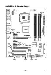
GA-X48-DS4 Motherboard Layout KB_MS RCA_SPDIF USB_1394_1 SYS_FAN1 ATX_12V_2X LGA775 CPU_FAN PHASE LED ATX USB_1394_2 USB_LAN1 USB_LAN2 AUDIO RTL8111C F_AUDIO PCIE_1 NB_FAN RTL8111C CODEC CD_IN PCIE_16_1 PCIE_2 PCIE_3 BP_BIOS MAIN_BIOS PCIE_16_2 Intel® X48 GA-X48-DS4 BAT CLR_CMOS Intel® ICH9R DDRII1 DDRII2 DDRII3 DDRII4 PWR_FAN FDD SATAII0 IDE SATAII1 SPDIF_O PCI1 IT8718 PCI2 LPT CI COM TPM F_1394 F_USB2 F_USB1 TSB43AB23 GIGABYTE SATA2 SATAII4 PWR_LED SATAII2 SATAII3 SPDIF_IN SYS_FAN2 F_PANEL SATAII5 - 7 -
GA-X48-DS4 Motherboard Layout KB_MS RCA_SPDIF USB_1394_1 SYS_FAN1 ATX_12V_2X LGA775 CPU_FAN PHASE LED ATX USB_1394_2 USB_LAN1 USB_LAN2 AUDIO RTL8111C F_AUDIO PCIE_1 NB_FAN RTL8111C CODEC CD_IN PCIE_16_1 PCIE_2 PCIE_3 BP_BIOS MAIN_BIOS PCIE_16_2 Intel® X48 GA-X48-DS4 BAT CLR_CMOS Intel® ICH9R DDRII1 DDRII2 DDRII3 DDRII4 PWR_FAN FDD SATAII0 IDE SATAII1 SPDIF_O PCI1 IT8718 PCI2 LPT CI COM TPM F_1394 F_USB2 F_USB1 TSB43AB23 GIGABYTE SATA2 SATAII4 PWR_LED SATAII2 SATAII3 SPDIF_IN SYS_FAN2 F_PANEL SATAII5 - 7 -

Manual
Page 8
... CLK (100 MHz) RJ45 RTL 8111C RJ45 RTL 8111C x1 x1 x1 x1 x1 PCI Express Bus ATA-133/100/66/ 33 IDE Channel GIGABYTE SATA2 Intel® X48 Intel® ICH9R Dual Channel Memory MCH CLK (400/333/266/200 MHz) Dual BIOS 6 SATA 3Gb/s 12 USB Ports PCI Bus TSB43AB23...
... CLK (100 MHz) RJ45 RTL 8111C RJ45 RTL 8111C x1 x1 x1 x1 x1 PCI Express Bus ATA-133/100/66/ 33 IDE Channel GIGABYTE SATA2 Intel® X48 Intel® ICH9R Dual Channel Memory MCH CLK (400/333/266/200 MHz) Dual BIOS 6 SATA 3Gb/s 12 USB Ports PCI Bus TSB43AB23...

Manual
Page 10
... chip Š Up to 3 IEEE 1394a ports (2 on the back panel, 1 via the IEEE 1394a bracket connected to the internal IEEE 1394a header) GA-X48-DS4 Motherboard - 10 - Support for Teaming Š 2 x PCI Express x16 slots supporting ATI CrossFireXTM technology (The PCI Express x16 slots conform to PCI Express...GB of system memory (Note 1) Š Dual channel memory architecture Š Support for DDR2 1200/1066/800/667 MHz memory modules (Go to GIGABYTE's website for the latest memory support list.) Š Support for ECC memory Š Realtek ALC889A codec Š High Definition Audio Š ...
... chip Š Up to 3 IEEE 1394a ports (2 on the back panel, 1 via the IEEE 1394a bracket connected to the internal IEEE 1394a header) GA-X48-DS4 Motherboard - 10 - Support for Teaming Š 2 x PCI Express x16 slots supporting ATI CrossFireXTM technology (The PCI Express x16 slots conform to PCI Express...GB of system memory (Note 1) Š Dual channel memory architecture Š Support for DDR2 1200/1066/800/667 MHz memory modules (Go to GIGABYTE's website for the latest memory support list.) Š Support for ECC memory Š Realtek ALC889A codec Š High Definition Audio Š ...

Manual
Page 12
... Setup (CPU/DDR2/PCIe) allow you to 700 MHz with 1 MHz increment - Adjust DDR2 frequency - Increase FSB voltage by 0.05V to 0.35V with 0.05V increment - GA-X48-DS4 Motherboard - 12 - Increase DDR2 voltage by 0.05V to 1.55V with 0.05V increment - Increase CPU voltage (Note 4) - Increase PCIe voltage by motherboard model. (Note 4) The adjustable...
... Setup (CPU/DDR2/PCIe) allow you to 700 MHz with 1 MHz increment - Adjust DDR2 frequency - Increase FSB voltage by 0.05V to 0.35V with 0.05V increment - GA-X48-DS4 Motherboard - 12 - Increase DDR2 voltage by 0.05V to 1.55V with 0.05V increment - Increase CPU voltage (Note 4) - Increase PCIe voltage by motherboard model. (Note 4) The adjustable...

Manual
Page 14
... one marking (triangle) with the pin one corner of the CPU socket (or you may align the CPU notches with your thumb and index fingers. GA-X48-DS4 Motherboard - 14 -
... one marking (triangle) with the pin one corner of the CPU socket (or you may align the CPU notches with your thumb and index fingers. GA-X48-DS4 Motherboard - 14 -

Manual
Page 16
...; Memory modules have a foolproof design. Intel® Flex Memory Technology offers greater flexibility to upgrade by allowing different memory sizes to be used . (Go to GIGABYTE's website for optimum performance. 1-4 Installing the Memory Read the following guidelines before you are unable to insert the memory, switch the direction. 1-4-1 Dual Channel Memory... Dual Channel Technology. When enabling Dual Channel mode with two or four memory modules, it is installed, the BIOS will double the original memory bandwidth. GA-X48-DS4 Motherboard - 16 -
...; Memory modules have a foolproof design. Intel® Flex Memory Technology offers greater flexibility to upgrade by allowing different memory sizes to be used . (Go to GIGABYTE's website for optimum performance. 1-4 Installing the Memory Read the following guidelines before you are unable to insert the memory, switch the direction. 1-4-1 Dual Channel Memory... Dual Channel Technology. When enabling Dual Channel mode with two or four memory modules, it is installed, the BIOS will double the original memory bandwidth. GA-X48-DS4 Motherboard - 16 -

Manual
Page 18
... Express x16 slot. Align the card with a screw. 5. 1-5 Installing an Expansion Card Read the following guidelines before installing an expansion card to prevent hardware damage. GA-X48-DS4 Motherboard - 18 - PCI Express x16 Slot PCI Express x1 Slot PCI Slot Follow the steps below to make any required BIOS changes for your expansion...
... Express x16 slot. Align the card with a screw. 5. 1-5 Installing an Expansion Card Read the following guidelines before installing an expansion card to prevent hardware damage. GA-X48-DS4 Motherboard - 18 - PCI Express x16 Slot PCI Express x1 Slot PCI Slot Follow the steps below to make any required BIOS changes for your expansion...

Manual
Page 20
... for an IEEE 1394a device. IEEE 1394a Port The IEEE 1394 port supports the IEEE 1394a specification, featuring high speed, high bandwidth and hotplug capabilities. GA-X48-DS4 Motherboard - 20 - Optical S/PDIF Out Connector This connector provides digital audio out to a back panel connector, first remove the cable from your audio system provides...
... for an IEEE 1394a device. IEEE 1394a Port The IEEE 1394 port supports the IEEE 1394a specification, featuring high speed, high bandwidth and hotplug capabilities. GA-X48-DS4 Motherboard - 20 - Optical S/PDIF Out Connector This connector provides digital audio out to a back panel connector, first remove the cable from your audio system provides...

Manual
Page 22
GA-X48-DS4 Motherboard - 22 - Unplug the power cord from the power outlet to prevent damage to the devices. • After installing the device and before connecting external ...
GA-X48-DS4 Motherboard - 22 - Unplug the power cord from the power outlet to prevent damage to the devices. • After installing the device and before connecting external ...

Manual
Page 24
... power voltage and possesses a foolproof insertion design. Definition 1 GND 2 +12V 3 NC • Be sure to connect fan cables to the fan headers to this header. GA-X48-DS4 Motherboard - 24 - When connecting a fan cable, be sure to connect it in the correct orientation. Definition 1 1 GND SYS_FAN2 2 Speed Control 3 Sense 4 +5V SYS_FAN1/PWR_FAN: Pin...
... power voltage and possesses a foolproof insertion design. Definition 1 GND 2 +12V 3 NC • Be sure to connect fan cables to the fan headers to this header. GA-X48-DS4 Motherboard - 24 - When connecting a fan cable, be sure to connect it in the correct orientation. Definition 1 1 GND SYS_FAN2 2 Speed Control 3 Sense 4 +5V SYS_FAN1/PWR_FAN: Pin...

Manual
Page 26
... is in S3/S4 sleep state or powered off (S5). Pin No. 1 2 3 Definition MPD+ MPDMPD- The ICH9R controller supports RAID 0, RAID 1, RAID 5 and RAID 10. GA-X48-DS4 Motherboard 1 - 26 - SATAII0 7 1 Pin No. 1 Definition GND 2 TXP 3 TXN 4 GND 1 7 SATAII1 5 RXN 6 RXP SATAII4 SATAII2 7 GND 7 17 1 1 71 7 SATAII5 SATAII3 Please connect the L-shaped end...
... is in S3/S4 sleep state or powered off (S5). Pin No. 1 2 3 Definition MPD+ MPDMPD- The ICH9R controller supports RAID 0, RAID 1, RAID 5 and RAID 10. GA-X48-DS4 Motherboard 1 - 26 - SATAII0 7 1 Pin No. 1 Definition GND 2 TXP 3 TXN 4 GND 1 7 SATAII1 5 RXN 6 RXP SATAII4 SATAII2 7 GND 7 17 1 1 71 7 SATAII5 SATAII3 Please connect the L-shaped end...

Manual
Page 28
... provides an AC'97 front panel audio module, refer to the instructions on each wire instead of the motherboard header. Definition 1 CD-L 2 GND 3 GND 4 CD-R GA-X48-DS4 Motherboard - 28 - Definition 1 MIC2_L Pin No. 1 Definition MIC 2 1 2 3 GND MIC2_R 2 GND 3 MIC Power 4 -ACZ_DET 4 NC 5 LINE2_R 5 Line Out (R) 6 GND 6 NC 7 FAUDIO_JD 7 NC 8 No Pin 8 No...
... provides an AC'97 front panel audio module, refer to the instructions on each wire instead of the motherboard header. Definition 1 CD-L 2 GND 3 GND 4 CD-R GA-X48-DS4 Motherboard - 28 - Definition 1 MIC2_L Pin No. 1 Definition MIC 2 1 2 3 GND MIC2_R 2 GND 3 MIC Power 4 -ACZ_DET 4 NC 5 LINE2_R 5 Line Out (R) 6 GND 6 NC 7 FAUDIO_JD 7 NC 8 No Pin 8 No...

Manual
Page 30
... to prevent damage to the IEEE 1394a bracket. • To connect an IEEE 1394a device, attach one IEEE 1394a port via an optional USB bracket. GA-X48-DS4 Motherboard - 30 - 16) F_USB1/F_USB2 (USB Headers, Yellow) The headers conform to USB 2.0/1.1 specification. Each USB header can provide one end of the device cable...
... to prevent damage to the IEEE 1394a bracket. • To connect an IEEE 1394a device, attach one IEEE 1394a port via an optional USB bracket. GA-X48-DS4 Motherboard - 30 - 16) F_USB1/F_USB2 (USB Headers, Yellow) The headers conform to USB 2.0/1.1 specification. Each USB header can provide one end of the device cable...

Manual
Page 32
This function requires a chassis with chassis intrusion detection design. Pin No. Definition 1 1 Signal 2 GND GA-X48-DS4 Motherboard - 32 - 20) COM (Serial Port Header) The COM header can provide one serial port via an optional COM port cable. For purchasing the optional COM port cable, please contact the local dealer. 2 10 1 9 Pin No. 1 2 3 4 5 6 7 8 9 10 Definition NDCD NSIN NSOUT NDTR GND NDSR NRTS NCTS NRI No Pin 21) CI (Chassis Intrusion Header) This motherboard provides a chassis detection feature that detects if the chassis cover has been removed.
This function requires a chassis with chassis intrusion detection design. Pin No. Definition 1 1 Signal 2 GND GA-X48-DS4 Motherboard - 32 - 20) COM (Serial Port Header) The COM header can provide one serial port via an optional COM port cable. For purchasing the optional COM port cable, please contact the local dealer. 2 10 1 9 Pin No. 1 2 3 4 5 6 7 8 9 10 Definition NDCD NSIN NSOUT NDTR GND NDSR NRTS NCTS NRI No Pin 21) CI (Chassis Intrusion Header) This motherboard provides a chassis detection feature that detects if the chassis cover has been removed.

Manual
Page 34
GA-X48-DS4 Motherboard - 34 - Gently remove the battery from the battery holder and wait for 5 seconds.) 3. Danger of explosion if the battery is turned off your computer ...
GA-X48-DS4 Motherboard - 34 - Gently remove the battery from the battery holder and wait for 5 seconds.) 3. Danger of explosion if the battery is turned off your computer ...

Manual
Page 36
... : BIOS Setup/Q-Flash : XpressRecovery2 : Boot Menu: Qflash Function Keys B. The system will still be used for one time only. GA-X48-DS4 Motherboard - 36 - X48-DS4 F1a . . . . : BIOS Setup : XpressRecovery2 : Boot Menu : Qflash 01/02/2008-X48-ICH9-6A89OG0WC-00 Function Keys Function Keys: : POST Screen Press the key to XpressRecovery2 during the POST. To exit...
... : BIOS Setup/Q-Flash : XpressRecovery2 : Boot Menu: Qflash Function Keys B. The system will still be used for one time only. GA-X48-DS4 Motherboard - 36 - X48-DS4 F1a . . . . : BIOS Setup : XpressRecovery2 : Boot Menu : Qflash 01/02/2008-X48-ICH9-6A89OG0WC-00 Function Keys Function Keys: : POST Screen Press the key to XpressRecovery2 during the POST. To exit...

