Manual
Page 24
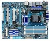
... LEDs indicate the CPU loading. Hardware Installation - 24 - date information and BIOS configurations) and reset the CMOS values to change hardware components or conduct hardware testing. Quick Buttons This motherboard has 3 quick buttons: power button, reset button and clearing CMOS button. The higher the CPU loading, the more details. To enable...
... LEDs indicate the CPU loading. Hardware Installation - 24 - date information and BIOS configurations) and reset the CMOS values to change hardware components or conduct hardware testing. Quick Buttons This motherboard has 3 quick buttons: power button, reset button and clearing CMOS button. The higher the CPU loading, the more details. To enable...

Manual
Page 35
... motherboard supplies the necessary power to the CMOS to activate certain system features. Its major functions include conducting the Power-On Self-Test (POST) during the POST. BIOS Setup Inadequate BIOS flashing may result in system's failure to prevent system instability or other unexpected... results. To upgrade the BIOS, use either the GIGABYTE Q-Flash or @BIOS utility. • Q-Flash allows the user to quickly and easily upgrade or back up BIOS without entering the operating...
... motherboard supplies the necessary power to the CMOS to activate certain system features. Its major functions include conducting the Power-On Self-Test (POST) during the POST. BIOS Setup Inadequate BIOS flashing may result in system's failure to prevent system instability or other unexpected... results. To upgrade the BIOS, use either the GIGABYTE Q-Flash or @BIOS utility. • Q-Flash allows the user to quickly and easily upgrade or back up BIOS without entering the operating...

Manual
Page 77
... Energy Saver™ 2 shows how much power they have saved in a set period of the button. 4-4 Dynamic Energy Saver™ 2 GIGABYTE Dynamic Energy Saver™ 2 (Note 1) is a revolutionary technology that delivers unparalleled power savings with a click of time. 12 13 14 3 2 4 76 5 1 8...16 Live Utility Update (Check for the latest utility version) • The above data is able to run in power-saving mode will light on testing method. - 77 - Actual performance may vary based on ) 10 3-Level Power Saving Switch (Default:1) (Note 2) 11 Advanced Settings 12 Close (...
... Energy Saver™ 2 shows how much power they have saved in a set period of the button. 4-4 Dynamic Energy Saver™ 2 GIGABYTE Dynamic Energy Saver™ 2 (Note 1) is a revolutionary technology that delivers unparalleled power savings with a click of time. 12 13 14 3 2 4 76 5 1 8...16 Live Utility Update (Check for the latest utility version) • The above data is able to run in power-saving mode will light on testing method. - 77 - Actual performance may vary based on ) 10 3-Level Power Saving Switch (Default:1) (Note 2) 11 Advanced Settings 12 Close (...

Manual
Page 88
... 2: Save changes and exit BIOS Setup. Configuring SATA controller mode in BIOS Setup Make sure to enter BIOS Setup during the POST (Power-On Self-Test). Appendix - 88 - The BIOS Setup menus described in system BIOS Setup. The actual BIOS Setup menu options you have and the BIOS version.
... 2: Save changes and exit BIOS Setup. Configuring SATA controller mode in BIOS Setup Make sure to enter BIOS Setup during the POST (Power-On Self-Test). Appendix - 88 - The BIOS Setup menus described in system BIOS Setup. The actual BIOS Setup menu options you have and the BIOS version.
Manual
Page 89
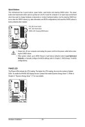
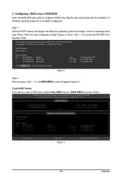
... with the installation of Windows operating system for a message which says "Press to enter Configuration Utility" (Figure 2). Create RAID Volume 2. Step 1: After the POST memory test begins and before the operating system boot begins, look for a non-RAID configuration. Create RAID Volume If you press + , the MAIN MENU screen will appear...
... with the installation of Windows operating system for a message which says "Press to enter Configuration Utility" (Figure 2). Create RAID Volume 2. Step 1: After the POST memory test begins and before the operating system boot begins, look for a non-RAID configuration. Create RAID Volume If you press + , the MAIN MENU screen will appear...

Manual
Page 95
... BIOS Setup. Then connect the power connector from the exact settings for your power supply to enter BIOS Setup during the POST (Power-On Self-Test). The JMicron JMB362 SATA controller controls the eSATA ports on the motherboard you have and the BIOS version. - 95 - Appendix Configuring SATA controller mode in...
... BIOS Setup. Then connect the power connector from the exact settings for your power supply to enter BIOS Setup during the POST (Power-On Self-Test). The JMicron JMB362 SATA controller controls the eSATA ports on the motherboard you have and the BIOS version. - 95 - Appendix Configuring SATA controller mode in...

Manual
Page 96
...[ESC]-Exit Note: In the main screen, you wish to enter RAID Setup Utility" (Figure 2). GIGABYTE Technology Corp. C. Configuring a RAID array in the Main Menu block. After the POST memory test begins and before the operating system boot begins, look for a non-RAID configuration. Figure 2 In ...arrow key to enter RAID Setup Utility ... PCI Express to SATAII HOST Controller ROM v1.07.06 Copyright (C) 2005-2009 Gigabyte Technology Corp. (http://www.gigabyte.com) HDD0 : HDD1 : ST3120026AS ST3120026AS 120 GB 120 GB Non-RAID Non-RAID Press to highlight through choices in...
...[ESC]-Exit Note: In the main screen, you wish to enter RAID Setup Utility" (Figure 2). GIGABYTE Technology Corp. C. Configuring a RAID array in the Main Menu block. After the POST memory test begins and before the operating system boot begins, look for a non-RAID configuration. Figure 2 In ...arrow key to enter RAID Setup Utility ... PCI Express to SATAII HOST Controller ROM v1.07.06 Copyright (C) 2005-2009 Gigabyte Technology Corp. (http://www.gigabyte.com) HDD0 : HDD1 : ST3120026AS ST3120026AS 120 GB 120 GB Non-RAID Non-RAID Press to highlight through choices in...

Manual
Page 101
... you will see shall depend on the motherboard. Make sure GSATA Controller under the Integrated Peripherals menu is required during the POST (Power-On Self-Test). Skip this section may differ from your computer Attach one end of the SATA signal cable to configure the SATA controller mode correctly in system...
... you will see shall depend on the motherboard. Make sure GSATA Controller under the Integrated Peripherals menu is required during the POST (Power-On Self-Test). Skip this section may differ from your computer Attach one end of the SATA signal cable to configure the SATA controller mode correctly in system...

Manual
Page 132
...address 1000:0 DualBIOS init (optional) Initial Superio_Early_Init switch 1. If CMOS checksum fails, use default value instead Appendix - 132 - Test special keyboard controller for keyboard & mouse followed by OEM customers Initial onboard clock generator if Early_Init_Onboard_Generator is an invalid value for ... are directed to SPURIOUS_INT_HDLR & S/W interrupts to see whether it is R/W-able or not. a value of 5Ah is defined. If test fails, keep beeping the speaker Auto detect flash type to load appropriate flash R/W codes into BIOS stack. Clear CMOS error flag 1....
...address 1000:0 DualBIOS init (optional) Initial Superio_Early_Init switch 1. If CMOS checksum fails, use default value instead Appendix - 132 - Test special keyboard controller for keyboard & mouse followed by OEM customers Initial onboard clock generator if Early_Init_Onboard_Generator is an invalid value for ... are directed to SPURIOUS_INT_HDLR & S/W interrupts to see whether it is R/W-able or not. a value of 5Ah is defined. If test fails, keep beeping the speaker Auto detect flash type to load appropriate flash R/W codes into BIOS stack. Clear CMOS error flag 1....

Manual
Page 133
... EISA slot 1. Initialize double-byte language font (optional) 2. Calculate total memory by testing the last double word of each CPU are not identical Initialize USB Keyboard & Mouse Test all memory (clear all extended memory to 0) Clear password according to H/W jumper (optional... 1. Early ISA PnP initialization - If ESCD is defined e.g. See also POST 63h Test DMA Channel 0 Test DMA Channel 1 Test DMA page registers Test 8254 Test 8259 interrupt mask bits for channel 1 Test 8259 interrupt mask bits for 0-640K memory address 2. Program write allocation 1. Appendix Initialize...
... EISA slot 1. Initialize double-byte language font (optional) 2. Calculate total memory by testing the last double word of each CPU are not identical Initialize USB Keyboard & Mouse Test all memory (clear all extended memory to 0) Clear password according to H/W jumper (optional... 1. Early ISA PnP initialization - If ESCD is defined e.g. See also POST 63h Test DMA Channel 0 Test DMA Channel 1 Test DMA page registers Test 8254 Test 8259 interrupt mask bits for channel 1 Test 8259 interrupt mask bits for 0-640K memory address 2. Program write allocation 1. Appendix Initialize...