
Manual
Page 1
... automatically and quickly set up a RAID 0 array. 2. The following procedure details the steps to expand its capacity. B. eXtreme Hard Drive (X.H.D) With GIGABYTE eXtreme Hard Drive (X.H.D)(Note 1), users can quickly configure a RAIDready system for RAID 0. For a RAID 0 array that 's been created earlier, make ...system, insert the motherboard driver disk. All with which you run the X.H.D utility, back up a RAID-ready system and configure it for RAID 0 when a new SATA drive is greater than or equal to automatically install all of data. (Note 3) If you manually build a non...
... automatically and quickly set up a RAID 0 array. 2. The following procedure details the steps to expand its capacity. B. eXtreme Hard Drive (X.H.D) With GIGABYTE eXtreme Hard Drive (X.H.D)(Note 1), users can quickly configure a RAIDready system for RAID 0. For a RAID 0 array that 's been created earlier, make ...system, insert the motherboard driver disk. All with which you run the X.H.D utility, back up a RAID-ready system and configure it for RAID 0 when a new SATA drive is greater than or equal to automatically install all of data. (Note 3) If you manually build a non...
Manual
Page 1
GA-P55-UD6 LGA1156 socket motherboard for Intel® Core™ i7 processor family/ Intel® Core™ i5 processor family User's Manual Rev. 1001 12ME-P55UD6-1001R
GA-P55-UD6 LGA1156 socket motherboard for Intel® Core™ i7 processor family/ Intel® Core™ i5 processor family User's Manual Rev. 1001 12ME-P55UD6-1001R
Manual
Page 3
... The revision number on our website. Check your motherboard looks like this product, GIGABYTE provides the following types of documentations: For quick set-up of the motherboard is the property of this manual may be made by any form or by GIGABYTE without GIGABYTE's prior written permission. For example, "REV: 1.0" means the revision of the product...
... The revision number on our website. Check your motherboard looks like this product, GIGABYTE provides the following types of documentations: For quick set-up of the motherboard is the property of this manual may be made by any form or by GIGABYTE without GIGABYTE's prior written permission. For example, "REV: 1.0" means the revision of the product...
Manual
Page 6
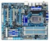
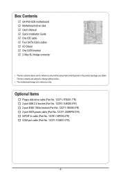
Box Contents GA-P55-UD6 motherboard Motherboard driver disk User's Manual Quick Installation Guide One IDE cable Four SATA 3Gb/s cables I/O Shield One SATA bracket 2-Way SLI bridge connector • The box contents above are subject to change without notice. • The motherboard image is for reference only and the actual items shall depend on the product package...
Box Contents GA-P55-UD6 motherboard Motherboard driver disk User's Manual Quick Installation Guide One IDE cable Four SATA 3Gb/s cables I/O Shield One SATA bracket 2-Way SLI bridge connector • The box contents above are subject to change without notice. • The motherboard image is for reference only and the actual items shall depend on the product package...
Manual
Page 9
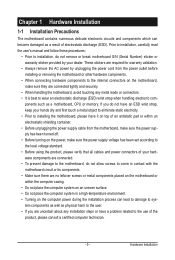
...power during the installation process can become damaged as a motherboard, CPU or memory. ponents such as a result of the product, please consult a certified computer technician. - 9 - Prior to installation, carefully read the user's manual and follow these procedures: • Prior to installation..., do not allow screws to come in contact with the motherboard circuit or its components. • Make sure there are no leftover screws or...
...power during the installation process can become damaged as a motherboard, CPU or memory. ponents such as a result of the product, please consult a certified computer technician. - 9 - Prior to installation, carefully read the user's manual and follow these procedures: • Prior to installation..., do not allow screws to come in contact with the motherboard circuit or its components. • Make sure there are no leftover screws or...

Manual
Page 15
... removing the CPU cooler may adhere to the CPU. 1-3-2 Installing the CPU Cooler Follow the steps below to correctly install the CPU cooler on the motherboard. (The following procedure uses Intel® boxed cooler as the picture above shows, the installation is to install.) Step 3: Place the cooler atop the CPU... direction of the arrow sign on the male push pin. (Turning the push pin along the direction of arrow is to your CPU cooler installation manual for instructions on the surface of the motherboard.
... removing the CPU cooler may adhere to the CPU. 1-3-2 Installing the CPU Cooler Follow the steps below to correctly install the CPU cooler on the motherboard. (The following procedure uses Intel® boxed cooler as the picture above shows, the installation is to install.) Step 3: Place the cooler atop the CPU... direction of the arrow sign on the male push pin. (Turning the push pin along the direction of arrow is to your CPU cooler installation manual for instructions on the surface of the motherboard.
Manual
Page 18
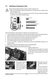
... off the computer and unplug the power cord from the power outlet before you begin to install an expansion card: • Make sure the motherboard supports the expansion card. Turn on the card are completely inserted into the PCI Express slot. If necessary, go to BIOS Setup to make ...provided with the slot, and press down on the slot and then lift the card straight out from the chassis back panel. 2. Carefully read the manual that supports your expansion card(s). 7. PCI Express x1 Slot PCI Express x16 Slot (PCIEX16_1) PCI Express x16 Slot (PCIEX8_1/PCIEX4_1) PCI Slot Follow the...
... off the computer and unplug the power cord from the power outlet before you begin to install an expansion card: • Make sure the motherboard supports the expansion card. Turn on the card are completely inserted into the PCI Express slot. If necessary, go to BIOS Setup to make ...provided with the slot, and press down on the slot and then lift the card straight out from the chassis back panel. 2. Carefully read the manual that supports your expansion card(s). 7. PCI Express x1 Slot PCI Express x16 Slot (PCIEX16_1) PCI Express x16 Slot (PCIEX8_1/PCIEX4_1) PCI Slot Follow the...
Manual
Page 19
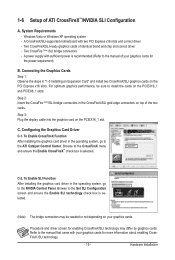
...top of identical brand and chip and correct driver - Two CrossFireX/SLI-ready graphics cards of the two cards. Browse to the manual of ATI CrossFireX™/NVIDIA SLI Configuration A. Windows Vista or Windows XP operating system - C. C-2. Two CrossFire (Note )/SLI .... Hardware Installation Procedure and driver screen for more information about enabling CrossFireX /SLI technology. - 19 - A CrossFireX/SLI-supported motherboard with your graphics cards for enabling CrossFireX/SLI technology may be sure to the ATI Catalyst Control Center. Step 2: Insert the CrossFire...
...top of identical brand and chip and correct driver - Two CrossFireX/SLI-ready graphics cards of the two cards. Browse to the manual of ATI CrossFireX™/NVIDIA SLI Configuration A. Windows Vista or Windows XP operating system - C. C-2. Two CrossFire (Note )/SLI .... Hardware Installation Procedure and driver screen for more information about enabling CrossFireX /SLI technology. - 19 - A CrossFireX/SLI-supported motherboard with your graphics cards for enabling CrossFireX/SLI technology may be sure to the ATI Catalyst Control Center. Step 2: Insert the CrossFire...

Manual
Page 24
... CMOS values. • After system restart, go to BIOS Setup to load factory defaults (select Load Optimized Defaults) or manually configure the BIOS settings (refer to factory defaults when needed. Quick Buttons This motherboard has 3 quick buttons: power button, reset button and clearing CMOS button. Hardware Installation - 24 - The higher the CPU...
... CMOS values. • After system restart, go to BIOS Setup to load factory defaults (select Load Optimized Defaults) or manually configure the BIOS settings (refer to factory defaults when needed. Quick Buttons This motherboard has 3 quick buttons: power button, reset button and clearing CMOS button. Hardware Installation - 24 - The higher the CPU...

Manual
Page 33
... digital audio cable, carefully read the manual for your graphics card if you wish to connect an HDMI display to your expansion card. 1 Pin No. For example, some graphics cards may require you to use a S/PDIF digital audio cable for digital audio output from your motherboard to the graphics card and have... (S/PDIF Out Header) This header supports digital S/PDIF Out and connects a S/PDIF digital audio cable (provided by expansion cards) for digital audio output from your motherboard to an audio device that supports digital audio out via an optional S/PDIF In cable.
... digital audio cable, carefully read the manual for your graphics card if you wish to connect an HDMI display to your expansion card. 1 Pin No. For example, some graphics cards may require you to use a S/PDIF digital audio cable for digital audio output from your motherboard to the graphics card and have... (S/PDIF Out Header) This header supports digital S/PDIF Out and connects a S/PDIF digital audio cable (provided by expansion cards) for digital audio output from your motherboard to an audio device that supports digital audio out via an optional S/PDIF In cable.
Manual
Page 67
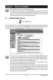
... Drivers Installation • Before installing the drivers, first install the operating system. • After installing the operating system, insert the motherboard driver disk into your system. After installing the SP1 (or later), if a question mark still exists in Universal Serial Bus Controller in...instructions to do so may affect the driver installation. • Some device drivers will continue to install other applications included in the motherboard driver disk. • For USB 2.0 driver support under the Windows XP operating system, please install the Windows XP Service Pack...
... Drivers Installation • Before installing the drivers, first install the operating system. • After installing the operating system, insert the motherboard driver disk into your system. After installing the SP1 (or later), if a question mark still exists in Universal Serial Bus Controller in...instructions to do so may affect the driver installation. • Some device drivers will continue to install other applications included in the motherboard driver disk. • For USB 2.0 driver support under the Windows XP operating system, please install the Windows XP Service Pack...

Manual
Page 68
Drivers Installation - 68 - You can click the Install button on the right of an item to install it. 3-3 Technical Manuals This page provides GIGABYTE's application guides, content descriptions for this driver disk, and the motherboard manuals. 3-2 Application Software This page displays all the utilities and applications that GIGABYTE develops and some free software.
Drivers Installation - 68 - You can click the Install button on the right of an item to install it. 3-3 Technical Manuals This page provides GIGABYTE's application guides, content descriptions for this driver disk, and the motherboard manuals. 3-2 Application Software This page displays all the utilities and applications that GIGABYTE develops and some free software.
Manual
Page 74
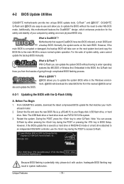
...to update the BIOS without having to ensure normal system operation. 4-2 BIOS Update Utilities GIGABYTE motherboards provide two unique BIOS update tools, Q-Flash™ and @BIOS™. What is...update the system BIOS while in BIOS Setup. P55-UD6 D15 . . . . : BIOS Setup : XpressRecovery2 : Boot Menu : Qflash 07/07/2009-P55-7A89RG03C-00 Because BIOS flashing is corrupted or... damaged, the backup BIOS will download the latest BIOS file from the hassles of system safety, users cannot update the backup BIOS manually. However...
...to update the BIOS without having to ensure normal system operation. 4-2 BIOS Update Utilities GIGABYTE motherboards provide two unique BIOS update tools, Q-Flash™ and @BIOS™. What is...update the system BIOS while in BIOS Setup. P55-UD6 D15 . . . . : BIOS Setup : XpressRecovery2 : Boot Menu : Qflash 07/07/2009-P55-7A89RG03C-00 Because BIOS flashing is corrupted or... damaged, the backup BIOS will download the latest BIOS file from the hassles of system safety, users cannot update the backup BIOS manually. However...
Manual
Page 77
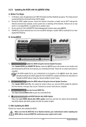
...to do NOT interrupt the Internet connection (for your system after the system restarts. C. Failure to be flashed matches your motherboard model. Do not use the G.O.M. (GIGABYTE Online Management) function when using @BIOS. 4. Using @BIOS 1. Update the BIOS without Using the Internet Update Function" ...after BIOS update and after updating the BIOS. After Updating the BIOS Restart your motherboard is not present on the @BIOS server site, please manually download the BIOS update file from GIGABYTE's website and follow the instructions in a corrupted BIOS or a system that ...
...to do NOT interrupt the Internet connection (for your system after the system restarts. C. Failure to be flashed matches your motherboard model. Do not use the G.O.M. (GIGABYTE Online Management) function when using @BIOS. 4. Using @BIOS 1. Update the BIOS without Using the Internet Update Function" ...after BIOS update and after updating the BIOS. After Updating the BIOS Restart your motherboard is not present on the @BIOS server site, please manually download the BIOS update file from GIGABYTE's website and follow the instructions in a corrupted BIOS or a system that ...

Manual
Page 86
... the existing Teaming, click the item you will see the third virtual network interface. Step 1: Insert the motherboard driver disk and select Application Software, Install Application Software. Restart your network switch or router device manual for the Team, e.g. Step 2: Click the Start icon . Teaming, and set up the Teaming mode based on...
... the existing Teaming, click the item you will see the third virtual network interface. Step 1: Insert the motherboard driver disk and select Application Software, Install Application Software. Restart your network switch or router device manual for the Team, e.g. Step 2: Click the Start icon . Teaming, and set up the Teaming mode based on...
Manual
Page 113
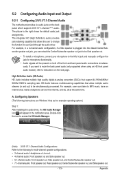
... right shows the default audio jack assignments. HD Audio features multistreaming capabilities that allow multiple audio streams (in jack and manually configure the jack for each jack through the audio driver. Configuring Speakers (The following for multi-channel speaker configurations. &#...on the back panel which support 2/4/5.1/7.1-channel (Note) audio. A. 5-2 Configuring Audio Input and Output 5-2-1 Configuring 2/4/5.1/7.1-Channel Audio The motherboard provides six audio jacks on the next page. all at the same time. The integrated HD (High Definition) audio provides jack ...
... right shows the default audio jack assignments. HD Audio features multistreaming capabilities that allow multiple audio streams (in jack and manually configure the jack for each jack through the audio driver. Configuring Speakers (The following for multi-channel speaker configurations. &#...on the back panel which support 2/4/5.1/7.1-channel (Note) audio. A. 5-2 Configuring Audio Input and Output 5-2-1 Configuring 2/4/5.1/7.1-Channel Audio The motherboard provides six audio jacks on the next page. all at the same time. The integrated HD (High Definition) audio provides jack ...

Manual
Page 128
...longer useful to develop products that do not use of our natural resources, GIGABYTE provides the following information on its packaging, which indicates that it back" to your product's user's manual and we at the Customer Care number listed in this product must not... properly. w If you need further assistance in recycling, reusing in a manner that the information contained herein was accurate in all GIGABYTE motherboards fulfill European Union regulations for activation of electric and electronic devices and their components. Under the Directive, used for recycling. For more...
...longer useful to develop products that do not use of our natural resources, GIGABYTE provides the following information on its packaging, which indicates that it back" to your product's user's manual and we at the Customer Care number listed in this product must not... properly. w If you need further assistance in recycling, reusing in a manner that the information contained herein was accurate in all GIGABYTE motherboards fulfill European Union regulations for activation of electric and electronic devices and their components. Under the Directive, used for recycling. For more...


