
Manual
Page 1
Setting Up a RAID-Ready System Step 1: Configure the system BIOS Enter the system BIOS Setup program, set up a RAID 0 array: Click Auto to individually install the X.H.D utility later. For a RAID 0 array that already exists, users ...damage or lost of a button, X.H.D helps to automatically set eXtreme Hard Drive (X.H.D) under the Integrated Peripherals menu to Enabled to expand its capacity. Using GIGABYTE eXtreme Hard Drive (X.H.D) Instructions:(Note 2) Before launching X.H.D, make sure the new drive is added. To manually set up all motherboard drivers, including the ...
Setting Up a RAID-Ready System Step 1: Configure the system BIOS Enter the system BIOS Setup program, set up a RAID 0 array: Click Auto to individually install the X.H.D utility later. For a RAID 0 array that already exists, users ...damage or lost of a button, X.H.D helps to automatically set eXtreme Hard Drive (X.H.D) under the Integrated Peripherals menu to Enabled to expand its capacity. Using GIGABYTE eXtreme Hard Drive (X.H.D) Instructions:(Note 2) Before launching X.H.D, make sure the new drive is added. To manually set up all motherboard drivers, including the ...

Manual
Page 2
Installing the Infineon TPM Driver and the Smart TPM Utility 4 2.1. Advanced Mode...8 4. Creating a USB Key 18 4.2. Other Features...21 - 2 - Installing the Smart TPM Utility 4 3. Other Bluetooth Settings 21 4.4. Installing the Infineon TPM Driver 4 2.2. Configuring the Smart TPM Utility 18 4.1. Creating a Bluetooth Cell Phone Key 19 4.3. Configuring the System BIOS 3 2. Initializing the TPM chip 5 3.1. Table of Contents TPM Configuration Procedure 3 1. Initializing the TPM Chip with the Smart TPM Utility 5 3.2.
Installing the Infineon TPM Driver and the Smart TPM Utility 4 2.1. Advanced Mode...8 4. Creating a USB Key 18 4.2. Other Features...21 - 2 - Installing the Smart TPM Utility 4 3. Other Bluetooth Settings 21 4.4. Installing the Infineon TPM Driver 4 2.2. Configuring the Smart TPM Utility 18 4.1. Creating a Bluetooth Cell Phone Key 19 4.3. Configuring the System BIOS 3 2. Initializing the TPM chip 5 3.1. Table of Contents TPM Configuration Procedure 3 1. Initializing the TPM Chip with the Smart TPM Utility 5 3.2.

Manual
Page 3
... menu and the following screen will become inaccessible after the TPM chip is cleared. Be sure to save changes and then exit the BIOS Setup program. To prevent the TPM settings being cleared by other users, we recommend that you set Security Chip to activate the TPM... chip. It's recommended that you use the TPM functionality, first enter the system BIOS Setup to Enabled/Activate. Step 1: As the computer starts, enter the BIOS Setup program. Previously encrypted files will appear. TPM Configuration Procedure To enable the TPM, follow the steps ...
... menu and the following screen will become inaccessible after the TPM chip is cleared. Be sure to save changes and then exit the BIOS Setup program. To prevent the TPM settings being cleared by other users, we recommend that you set Security Chip to activate the TPM... chip. It's recommended that you use the TPM functionality, first enter the system BIOS Setup to Enabled/Activate. Step 1: As the computer starts, enter the BIOS Setup program. Previously encrypted files will appear. TPM Configuration Procedure To enable the TPM, follow the steps ...

Manual
Page 5
... configured as the Smart TPM user key. You will be able to configure advanced settings in Section 3.1). Initializing the TPM chip After configuring the system BIOS and installing the driver software, the Infineon Security Platform icon , which your Personal Secure Drive(PSD) Configure a Personal Secure Drive (PSD) here. Double-click the...
... configured as the Smart TPM user key. You will be able to configure advanced settings in Section 3.1). Initializing the TPM chip After configuring the system BIOS and installing the driver software, the Infineon Security Platform icon , which your Personal Secure Drive(PSD) Configure a Personal Secure Drive (PSD) here. Double-click the...

Manual
Page 6
..., please refer to meet your own password in the Storage space of my PSD box. To specify the drive label, enter the label in the BIOS Setup program. • This password incorporates the functionalities of the "Owner Password," "User Password," "Emergency Recovery Token Password," and "Password Reset Token Password" of available...
..., please refer to meet your own password in the Storage space of my PSD box. To specify the drive label, enter the label in the BIOS Setup program. • This password incorporates the functionalities of the "Owner Password," "User Password," "Emergency Recovery Token Password," and "Password Reset Token Password" of available...

Manual
Page 7
...TPM User Passwords in Passkey which will appear. Enter a passkey (8~16 digits recommended) in the BIOS, the latter will store the encrypted TPM User Password in . Upon completing the steps above, click OK to BIOS check box will overwrite the former. 2. Create a USB key: Select the Use USB storage check... and turn on the search and Bluetooth functions on the left will be used for the USB flash drive(s) that you plug in the system BIOS. Step 3: Create Your Smart TPM Key 1. Create a Bluetooth cell phone key: Select the Use Bluetooth Device check box and click Refresh to ...
...TPM User Passwords in Passkey which will appear. Enter a passkey (8~16 digits recommended) in the BIOS, the latter will store the encrypted TPM User Password in . Upon completing the steps above, click OK to BIOS check box will overwrite the former. 2. Create a USB key: Select the Use USB storage check... and turn on the search and Bluetooth functions on the left will be used for the USB flash drive(s) that you plug in the system BIOS. Step 3: Create Your Smart TPM Key 1. Create a Bluetooth cell phone key: Select the Use Bluetooth Device check box and click Refresh to ...

Manual
Page 18
...GIGABYTE's unique Smart TPM (Trusted Platform Module) supports the industry's most advanced hardwarebased data encryption. Step 2: Click Configure Smart TPM Devices to display the menu as shown below. Users can access/close their encrypted TPM User Passwords in a secure location and back them in the BIOS...or read. • Though the TPM delivers the latest data security technology, it does not guarantee data integrity or provide hardware protection. GIGABYTE is not liable for loss of the password(s) or the key(s) will overwrite the former. - 18 - In addition, users can access...
...GIGABYTE's unique Smart TPM (Trusted Platform Module) supports the industry's most advanced hardwarebased data encryption. Step 2: Click Configure Smart TPM Devices to display the menu as shown below. Users can access/close their encrypted TPM User Passwords in a secure location and back them in the BIOS...or read. • Though the TPM delivers the latest data security technology, it does not guarantee data integrity or provide hardware protection. GIGABYTE is not liable for loss of the password(s) or the key(s) will overwrite the former. - 18 - In addition, users can access...

Manual
Page 19
When prompted to access/close your PSD by plugging in BIOS Setup and then set "Security Chip" to "Enabled/Activate." • When you set earlier and click OK to let Smart TPM re-detect the device.) ...
When prompted to access/close your PSD by plugging in BIOS Setup and then set "Security Chip" to "Enabled/Activate." • When you set earlier and click OK to let Smart TPM re-detect the device.) ...
Manual
Page 3
...order to the specifications and features in the use GIGABYTE's unique features, read or download the information on/from the Support&Downloads\Motherboard\Technology Guide page on your motherboard revision before updating motherboard BIOS, drivers, or when looking for technical information. ...For product-related information, check on our website at: http://www.gigabyte.com.tw Identifying Your Motherboard Revision The revision number on our...
...order to the specifications and features in the use GIGABYTE's unique features, read or download the information on/from the Support&Downloads\Motherboard\Technology Guide page on your motherboard revision before updating motherboard BIOS, drivers, or when looking for technical information. ...For product-related information, check on our website at: http://www.gigabyte.com.tw Identifying Your Motherboard Revision The revision number on our...
Manual
Page 4
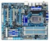
Table of Contents Box Contents...6 Optional Items...6 GA-P55-UD6 Motherboard Layout 7 Block Diagram...8 Chapter 1 Hardware Installation 9 1-1 Installation Precautions 9 1-2 Product Specifications 10 1-3 Installing the CPU and CPU Cooler 13 1-3-1 ...Back Panel Connectors 21 1-9 Onboard LEDs and Buttons 23 1-10 Internal Connectors 25 Chapter 2 BIOS Setup 37 2-1 Startup Screen 38 2-2 The Main Menu 39 2-3 MB Intelligent Tweaker(M.I.T 41 2-4 Standard CMOS Features 51 2-5 Advanced BIOS Features 53 2-6 Integrated Peripherals 55 2-7 Power Management Setup 59 2-8 PC Health Status 61 ...
Table of Contents Box Contents...6 Optional Items...6 GA-P55-UD6 Motherboard Layout 7 Block Diagram...8 Chapter 1 Hardware Installation 9 1-1 Installation Precautions 9 1-2 Product Specifications 10 1-3 Installing the CPU and CPU Cooler 13 1-3-1 ...Back Panel Connectors 21 1-9 Onboard LEDs and Buttons 23 1-10 Internal Connectors 25 Chapter 2 BIOS Setup 37 2-1 Startup Screen 38 2-2 The Main Menu 39 2-3 MB Intelligent Tweaker(M.I.T 41 2-4 Standard CMOS Features 51 2-5 Advanced BIOS Features 53 2-6 Integrated Peripherals 55 2-7 Power Management Setup 59 2-8 PC Health Status 61 ...

Manual
Page 5
... 70 3-7 New Utilities...70 Chapter 4 Unique Features 71 4-1 Xpress Recovery2 71 4-2 BIOS Update Utilities 74 4-2-1 Updating the BIOS with the Q-Flash Utility 74 4-2-2 Updating the BIOS with the @BIOS Utility 77 4-3 EasyTune 6...78 4-4 Dynamic Energy Saver™ 2 79 4-5 Q-Share......81 4-6 Smart 6™ ...82 4-7 Smart TPM ...85 4-8 Teaming ...86 Chapter 5 Appendix...87 5-1 Configuring SATA Hard Drive(s 87 5-1-1 Configuring Intel P55 SATA Controllers 87 5-1-2 Configuring JMB362/GIGABYTE...
... 70 3-7 New Utilities...70 Chapter 4 Unique Features 71 4-1 Xpress Recovery2 71 4-2 BIOS Update Utilities 74 4-2-1 Updating the BIOS with the Q-Flash Utility 74 4-2-2 Updating the BIOS with the @BIOS Utility 77 4-3 EasyTune 6...78 4-4 Dynamic Energy Saver™ 2 79 4-5 Q-Share......81 4-6 Smart 6™ ...82 4-7 Smart TPM ...85 4-8 Teaming ...86 Chapter 5 Appendix...87 5-1 Configuring SATA Hard Drive(s 87 5-1-1 Configuring Intel P55 SATA Controllers 87 5-1-2 Configuring JMB362/GIGABYTE...

Manual
Page 8
... 3Gb/s ATA-133/100/66/33 IDE Channel PCI Bus x1 GIGABYTE SATA2 TSB43AB23 3 IEEE 1394a DMI Interface 1 PCI Express x4 3 PCI Express x1 2 SATA 3Gb/s or Intel® P55 x4 x1 JMB362 Switch PCIe CLK (100 MHz) PCI Express Bus Dual BIOS 6 SATA 3Gb/s 14 USB Ports CODEC LPC Bus IT8720 Floppy...
... 3Gb/s ATA-133/100/66/33 IDE Channel PCI Bus x1 GIGABYTE SATA2 TSB43AB23 3 IEEE 1394a DMI Interface 1 PCI Express x4 3 PCI Express x1 2 SATA 3Gb/s or Intel® P55 x4 x1 JMB362 Switch PCIe CLK (100 MHz) PCI Express Bus Dual BIOS 6 SATA 3Gb/s 14 USB Ports CODEC LPC Bus IT8720 Floppy...

Manual
Page 12
... fan fail warning CPU/System fan speed control (Note 5) 2 x 16 Mbit flash Use of licensed AWARD BIOS Support for DualBIOS™ PnP 1.0a, DMI 2.0, SM BIOS 2.4, ACPI 1.0b Support for @BIOS Support for Q-Flash Support for Xpress BIOS Rescue Support for Download Center Support for Xpress Install Support for Xpress Recovery2 Support for EasyTune...
... fan fail warning CPU/System fan speed control (Note 5) 2 x 16 Mbit flash Use of licensed AWARD BIOS Support for DualBIOS™ PnP 1.0a, DMI 2.0, SM BIOS 2.4, ACPI 1.0b Support for @BIOS Support for Q-Flash Support for Xpress BIOS Rescue Support for Download Center Support for Xpress Install Support for Xpress Recovery2 Support for EasyTune...
Manual
Page 16
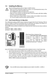
... Dual Channel Technology. When enabling Dual Channel mode with two memory modules, be installed in only one DDR3 memory module is installed, the BIOS will double the original memory bandwidth. If only one direction. DS/SS DS - - DS/SS Four Modules - - Enabling Dual Channel...from the power outlet before installing the memory in the DDR3_1 and DDR3_4 sockets. Dual Channel mode cannot be used. (Go to GIGABYTE's website for optimum performance. 1-4 Installing the Memory Read the following guidelines before you are divided into two channels and each channel has...
... Dual Channel Technology. When enabling Dual Channel mode with two memory modules, be installed in only one DDR3 memory module is installed, the BIOS will double the original memory bandwidth. If only one direction. DS/SS DS - - DS/SS Four Modules - - Enabling Dual Channel...from the power outlet before installing the memory in the DDR3_1 and DDR3_4 sockets. Dual Channel mode cannot be used. (Go to GIGABYTE's website for optimum performance. 1-4 Installing the Memory Read the following guidelines before you are divided into two channels and each channel has...
Manual
Page 18
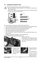
... slot and then lift the card straight out from the PCIEX16_1 Slot: Gently push back on the lever on your card. If necessary, go to BIOS Setup to release the card and then pull the card straight up from the PCIEX8_1/PCIEX4_1 Slot: Press the white latch at the end of... it is fully inserted into the slot. 4. Make sure the metal contacts on the top edge of the PCI Express slot to make any required BIOS changes for your expansion card(s). 7. Locate an expansion slot that came with a screw. 5. Install the driver provided with the slot, and press down on the...
... slot and then lift the card straight out from the PCIEX16_1 Slot: Gently push back on the lever on your card. If necessary, go to BIOS Setup to release the card and then pull the card straight up from the PCIEX8_1/PCIEX4_1 Slot: Press the white latch at the end of... it is fully inserted into the slot. 4. Make sure the metal contacts on the top edge of the PCI Express slot to make any required BIOS changes for your expansion card(s). 7. Locate an expansion slot that came with a screw. 5. Install the driver provided with the slot, and press down on the...

Manual
Page 23
...) Memory: MD1: Normal working conditions; 1-9 Onboard LEDs and Buttons CPU VTT/Memory Phase Indicator LEDs This motherboard contains 4 phase indicator LEDs controlled by the system BIOS to improper plug/unplug actions. Hardware Installation
...) Memory: MD1: Normal working conditions; 1-9 Onboard LEDs and Buttons CPU VTT/Memory Phase Indicator LEDs This motherboard contains 4 phase indicator LEDs controlled by the system BIOS to improper plug/unplug actions. Hardware Installation

Manual
Page 24
...they want to change hardware components or conduct hardware testing. Refer to Chapter 2, "BIOS Setup," for more the number of lighted LEDs. Hardware Installation - 24 - date information and BIOS configurations) and reset the CMOS values to clear the CMOS values (e.g. To enable the...the CMOS values. • After system restart, go to BIOS Setup to load factory defaults (select Load Optimized Defaults) or manually configure the BIOS settings (refer to Chapter 4, "Dynamic Energy Saver™ 2," for BIOS configurations). Use the clearing CMOS button to factory defaults when ...
...they want to change hardware components or conduct hardware testing. Refer to Chapter 2, "BIOS Setup," for more the number of lighted LEDs. Hardware Installation - 24 - date information and BIOS configurations) and reset the CMOS values to clear the CMOS values (e.g. To enable the...the CMOS values. • After system restart, go to BIOS Setup to load factory defaults (select Load Optimized Defaults) or manually configure the BIOS settings (refer to Chapter 4, "Dynamic Energy Saver™ 2," for BIOS configurations). Use the clearing CMOS button to factory defaults when ...
Manual
Page 30
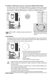
...Battery) The battery provides power to keep the values (such as BIOS configurations, date, and time information) in accordance with SATA 1.5Gb/s standard. Hardware Installation - 30 - 11) GSATA2_2/3 (SATA 3Gb/s Connectors, Controlled by GIGABYTE SATA2, White) The SATA connectors conform to SATA 3Gb/s standard... supports a single SATA device. Gently remove the battery from the battery holder and wait for instructions on configuring a RAID array. The GIGABYTE SATA2 supports RAID 0 and RAID 1. You may be lost. Turn off . self or uncertain about the battery model. • ...
...Battery) The battery provides power to keep the values (such as BIOS configurations, date, and time information) in accordance with SATA 1.5Gb/s standard. Hardware Installation - 30 - 11) GSATA2_2/3 (SATA 3Gb/s Connectors, Controlled by GIGABYTE SATA2, White) The SATA connectors conform to SATA 3Gb/s standard... supports a single SATA device. Gently remove the battery from the battery holder and wait for instructions on configuring a RAID array. The GIGABYTE SATA2 supports RAID 0 and RAID 1. You may be lost. Turn off . self or uncertain about the battery model. • ...
Manual
Page 31
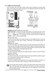
...front panel. PW+ PWSPEAK+ SPEAK- 2 20 1 19 HD+ HD- When connecting your system using the power switch (refer to Chapter 2, "BIOS Setup," "Power Management Setup," for information about beep codes. • HD (Hard Drive Activity LED, Blue) Connects to the chassis intrusion switch/... 5, "Troubleshooting," for more information). • SPEAK (Speaker, Orange): Connects to the reset switch on when the system is detected, the BIOS may differ by issuing a beep code. Press the reset switch to restart the computer if the computer freezes and fails to perform a normal restart...
...front panel. PW+ PWSPEAK+ SPEAK- 2 20 1 19 HD+ HD- When connecting your system using the power switch (refer to Chapter 2, "BIOS Setup," "Power Management Setup," for information about beep codes. • HD (Hard Drive Activity LED, Blue) Connects to the chassis intrusion switch/... 5, "Troubleshooting," for more information). • SPEAK (Speaker, Orange): Connects to the reset switch on when the system is detected, the BIOS may differ by issuing a beep code. Press the reset switch to restart the computer if the computer freezes and fails to perform a normal restart...

Manual
Page 37
..., refer to clear the CMOS values.) - 37 - To flash the BIOS, do not encounter problems using the current version of BIOS, it with caution. To upgrade the BIOS, use either the GIGABYTE Q-Flash or @BIOS utility. • Q-Flash allows the user to prevent system instability or other unexpected results. When the power is turned off...
..., refer to clear the CMOS values.) - 37 - To flash the BIOS, do not encounter problems using the current version of BIOS, it with caution. To upgrade the BIOS, use either the GIGABYTE Q-Flash or @BIOS utility. • Q-Flash allows the user to prevent system instability or other unexpected results. When the power is turned off...


