
Manual
Page 4
Table of Contents Box Contents...6 Optional Items...6 GA-P55-UD5 Motherboard Layout 7 Block Diagram...8 Chapter 1 Hardware Installation 9 1-1 Installation Precautions 9 1-2 Product Specifications 10 1-3 Installing the CPU and CPU Cooler 13 1-3-1 Installing... the Memory 16 1-4-1 Dual Channel Memory Configuration 16 1-4-2 Installing a Memory 17 1-5 Installing an Expansion Card 18 1-6 Setup of ATI CrossFireX™/NVIDIA SLI Configuration 19 1-7 Installing the SATA Bracket 20 1-8 Back Panel Connectors 21 1-9 Onboard LEDs and Buttons 23 1-10 Internal Connectors 25 Chapter 2 BIOS Setup...
Table of Contents Box Contents...6 Optional Items...6 GA-P55-UD5 Motherboard Layout 7 Block Diagram...8 Chapter 1 Hardware Installation 9 1-1 Installation Precautions 9 1-2 Product Specifications 10 1-3 Installing the CPU and CPU Cooler 13 1-3-1 Installing... the Memory 16 1-4-1 Dual Channel Memory Configuration 16 1-4-2 Installing a Memory 17 1-5 Installing an Expansion Card 18 1-6 Setup of ATI CrossFireX™/NVIDIA SLI Configuration 19 1-7 Installing the SATA Bracket 20 1-8 Back Panel Connectors 21 1-9 Onboard LEDs and Buttons 23 1-10 Internal Connectors 25 Chapter 2 BIOS Setup...

Manual
Page 6
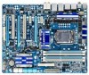
The box contents are for reference only. Box Contents GA-P55-UD5 motherboard Motherboard driver disk User's Manual Quick Installation Guide One IDE cable Four SATA 3Gb/s cables I/O Shield One SATA bracket 2-Way SLI bridge connector • The box contents above are subject to change without notice. • The motherboard image is for reference only...
The box contents are for reference only. Box Contents GA-P55-UD5 motherboard Motherboard driver disk User's Manual Quick Installation Guide One IDE cable Four SATA 3Gb/s cables I/O Shield One SATA bracket 2-Way SLI bridge connector • The box contents above are subject to change without notice. • The motherboard image is for reference only...

Manual
Page 10
...; Core™ i5 series processor in the LGA1156 package (Go to GIGABYTE's website for the latest CPU support list.) L3 cache varies with CPU Chipset Intel® P55 Express Chipset Memory 4 x 1.5V DDR3 DIMM sockets supporting ...PCIEX4_1) (Note 4) 2 x PCI Express x1 slots 2 x PCI slots Multi-Graphics Support for ATI CrossFireX™/NVIDIA SLI technology Technology (The PCIEX16_1 and PCIEX8_1 slots only.) Storage Interface Chipset: - 6 x SATA 3Gb/s connectors (SATA2_0, SATA2_1, SATA2_2, SATA2_3, ...
...; Core™ i5 series processor in the LGA1156 package (Go to GIGABYTE's website for the latest CPU support list.) L3 cache varies with CPU Chipset Intel® P55 Express Chipset Memory 4 x 1.5V DDR3 DIMM sockets supporting ...PCIEX4_1) (Note 4) 2 x PCI Express x1 slots 2 x PCI slots Multi-Graphics Support for ATI CrossFireX™/NVIDIA SLI technology Technology (The PCIEX16_1 and PCIEX8_1 slots only.) Storage Interface Chipset: - 6 x SATA 3Gb/s connectors (SATA2_0, SATA2_1, SATA2_2, SATA2_3, ...

Manual
Page 19
...supply with two PCI Express x16 slots and correct driver - Step 2: Insert the CrossFire (Note)/SLI bridge connectors in "1-5 Installing an Expansion Card" and install two CrossFireX/SLI graphics cards on the PCI Express x16 slots. To Enable CrossFireX Function After installing the graphics card... system, go to the manual of the two cards. C-2. Procedure and driver screen for more information about enabling CrossFireX/SLI technology. - 19 - Two CrossFire (Note )/SLI bridge connectors - Step 3: Plug the display cable into the graphics card on top of your graphics cards for the ...
...supply with two PCI Express x16 slots and correct driver - Step 2: Insert the CrossFire (Note)/SLI bridge connectors in "1-5 Installing an Expansion Card" and install two CrossFireX/SLI graphics cards on the PCI Express x16 slots. To Enable CrossFireX Function After installing the graphics card... system, go to the manual of the two cards. C-2. Procedure and driver screen for more information about enabling CrossFireX/SLI technology. - 19 - Two CrossFire (Note )/SLI bridge connectors - Step 3: Plug the display cable into the graphics card on top of your graphics cards for the ...


