
Manual
Page 1
GA-P55-UD4P GA-P55-UD4 LGA1156 socket motherboard for Intel® Core™ i7 processor family/ Intel® Core™ i5 processor family User's Manual Rev. 1001 12ME-P55UD4P-1001R
GA-P55-UD4P GA-P55-UD4 LGA1156 socket motherboard for Intel® Core™ i7 processor family/ Intel® Core™ i5 processor family User's Manual Rev. 1001 12ME-P55UD4P-1001R

Manual
Page 4
Table of Contents Box Contents...6 Optional Items...6 GA-P55-UD4P/GA-P55-UD4 Motherboard Layout 7 Block Diagram...8 Chapter 1 Hardware Installation 9 1-1 Installation Precautions 9 1-2 Product Specifications 10 1-3 Installing the CPU and CPU Cooler 13 1-3-1 Installing the CPU 13 1-3-2 Installing the ...
Table of Contents Box Contents...6 Optional Items...6 GA-P55-UD4P/GA-P55-UD4 Motherboard Layout 7 Block Diagram...8 Chapter 1 Hardware Installation 9 1-1 Installation Precautions 9 1-2 Product Specifications 10 1-3 Installing the CPU and CPU Cooler 13 1-3-1 Installing the CPU 13 1-3-2 Installing the ...
Manual
Page 5
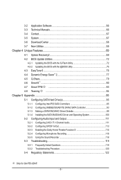
... Q-Share...79 4-6 Smart 6™ ...80 4-7 Smart TPM j 83 4-8 Teaming j 84 Chapter 5 Appendix...85 5-1 Configuring SATA Hard Drive(s 85 5-1-1 Configuring Intel P55 SATA Controllers 85 5-1-2 Configuring JMB362/GIGABYTE SATA2 SATA Controller 93 5-1-3 Making a SATA RAID/AHCI Driver Diskette 99 5-1-4 Installing the SATA RAID/AHCI Driver and Operating System 100 5-2 Configuring Audio... Recording 116 5-2-5 Using the Sound Recorder 118 5-3 Troubleshooting 119 5-3-1 Frequently Asked Questions 119 5-3-2 Troubleshooting Procedure 120 5-4 Regulatory Statements 122 j Only for GA-P55-UD4P. - 5 -
... Q-Share...79 4-6 Smart 6™ ...80 4-7 Smart TPM j 83 4-8 Teaming j 84 Chapter 5 Appendix...85 5-1 Configuring SATA Hard Drive(s 85 5-1-1 Configuring Intel P55 SATA Controllers 85 5-1-2 Configuring JMB362/GIGABYTE SATA2 SATA Controller 93 5-1-3 Making a SATA RAID/AHCI Driver Diskette 99 5-1-4 Installing the SATA RAID/AHCI Driver and Operating System 100 5-2 Configuring Audio... Recording 116 5-2-5 Using the Sound Recorder 118 5-3 Troubleshooting 119 5-3-1 Frequently Asked Questions 119 5-3-2 Troubleshooting Procedure 120 5-4 Regulatory Statements 122 j Only for GA-P55-UD4P. - 5 -

Manual
Page 6
...-2SERPW-0*R) S/PDIF In cable (Part No. 12CR1-1SPDIN-0*R) COM port cable (Part No. 12CF1-1CM001-3*R) LPT port cable (Part No. 12CF1-1LP001-0*R) - 6 - Box Contents GA-P55-UD4P or GA-P55-UD4 motherboard Motherboard driver disk User's Manual Quick Installation Guide One IDE cable Four SATA 3Gb/s cables 2-Way SLI bridge connector I/O Shield • The box...
...-2SERPW-0*R) S/PDIF In cable (Part No. 12CR1-1SPDIN-0*R) COM port cable (Part No. 12CF1-1CM001-3*R) LPT port cable (Part No. 12CF1-1LP001-0*R) - 6 - Box Contents GA-P55-UD4P or GA-P55-UD4 motherboard Motherboard driver disk User's Manual Quick Installation Guide One IDE cable Four SATA 3Gb/s cables 2-Way SLI bridge connector I/O Shield • The box...

Manual
Page 7
... F_AUDIO SYS_FAN1 PCIEX1_1(Note) PCIEX16 RTL8111D j PCIEX1_2 CD_IN SPDIF_I SPDIF_O CODEC PCIEX1_3 PCIEX8 PCI1 BATTERY TPM IC j TSB43AB23 GA-P55-UD4P / GA-P55-UD4 DDR3_2 DDR3_1 PHASE LED ATX PWR_FAN IDE DDR3_4 DDR3_3 GIGABYTE SATA2 B_BIOS Intel® P55 M_BIOS SYS_FAN2 PCH_FAN CLR_CMOS GSATA2_1 GSATA2_0 SATA2_1 SATA2_0 SATA2_3 SATA2_2 SATA2_5 SATA2_4 IT8720 PCI2 LPT COMA FDD F1_1394...
... F_AUDIO SYS_FAN1 PCIEX1_1(Note) PCIEX16 RTL8111D j PCIEX1_2 CD_IN SPDIF_I SPDIF_O CODEC PCIEX1_3 PCIEX8 PCI1 BATTERY TPM IC j TSB43AB23 GA-P55-UD4P / GA-P55-UD4 DDR3_2 DDR3_1 PHASE LED ATX PWR_FAN IDE DDR3_4 DDR3_3 GIGABYTE SATA2 B_BIOS Intel® P55 M_BIOS SYS_FAN2 PCH_FAN CLR_CMOS GSATA2_1 GSATA2_0 SATA2_1 SATA2_0 SATA2_3 SATA2_2 SATA2_5 SATA2_4 IT8720 PCI2 LPT COMA FDD F1_1394...

Manual
Page 8
...x1 x1 (100 MHz) x1 3 PCI Express x1 2 SATA 3Gb/s ATA-133/100/66/33 IDE Channel PCI Bus GIGABYTE SATA2 TSB43AB23 3 IEEE 1394a LGA1156 CPU CPU CLK+/- (133 MHz) DDR3 2200/1333/1066/800 MHz Dual Channel Memory DMI Interface Intel&#...174; P55 PCI Express Bus x1 2 SATA 3Gb/s JMB362 Dual BIOS 6 SATA 3Gb/s 14 USB Ports CODEC LPC Bus IT8720 Floppy COM Port... Speaker Out MIC Line Out Line In S/PDIF In S/PDIF Out 2 PCI PCI CLK (33 MHz) j Only for GA-P55-UD4P. - 8 -
...x1 x1 (100 MHz) x1 3 PCI Express x1 2 SATA 3Gb/s ATA-133/100/66/33 IDE Channel PCI Bus GIGABYTE SATA2 TSB43AB23 3 IEEE 1394a LGA1156 CPU CPU CLK+/- (133 MHz) DDR3 2200/1333/1066/800 MHz Dual Channel Memory DMI Interface Intel&#...174; P55 PCI Express Bus x1 2 SATA 3Gb/s JMB362 Dual BIOS 6 SATA 3Gb/s 14 USB Ports CODEC LPC Bus IT8720 Floppy COM Port... Speaker Out MIC Line Out Line In S/PDIF In S/PDIF Out 2 PCI PCI CLK (33 MHz) j Only for GA-P55-UD4P. - 8 -

Manual
Page 10
...1 x floppy disk drive connector supporting up to 2 SATA 3Gb/s devices - Support for SATA RAID 0, RAID 1, RAID 5, and RAID 10 GIGABYTE SATA2 chip: - 1 x IDE connector supporting ATA-133/100/66/33 and up to 2 IDE devices - 2 x SATA 3Gb/s connectors (GSATA2_0, ... SATA2 chip: - 2 x eSATA 3Gb/s connectors on the back panel supporting up to 6 SATA 3Gb/s devices - k Only for GA-P55-UD4. 1-2 Product Specifications CPU Support for an Intel® Core™ i7 series processor/Intel® Core™ i5 series processor in the...
...1 x floppy disk drive connector supporting up to 2 SATA 3Gb/s devices - Support for SATA RAID 0, RAID 1, RAID 5, and RAID 10 GIGABYTE SATA2 chip: - 1 x IDE connector supporting ATA-133/100/66/33 and up to 2 IDE devices - 2 x SATA 3Gb/s connectors (GSATA2_0, ... SATA2 chip: - 2 x eSATA 3Gb/s connectors on the back panel supporting up to 6 SATA 3Gb/s devices - k Only for GA-P55-UD4. 1-2 Product Specifications CPU Support for an Intel® Core™ i7 series processor/Intel® Core™ i5 series processor in the...

Manual
Page 11
k Only for GA-P55-UD4P. Hardware Installation TSB43AB23 chip Up to 3 IEEE 1394a ports (2 on the back panel, 1 via the USB brackets connected to the internal USB headers) T.I /O Controller w...j 1 x RJ-45 port k 6 x audio jacks (Center/Subwoofer Speaker Out/Rear Speaker Out/ Side Speaker Out/Line In/Line Out/Microphone) iTE IT8720 chip j Only for GA-P55-UD4. - 11 - USB IEEE 1394 Internal w Connectors w w w w w w w w w w w w w w w w w w Back Panel w Connectors...
k Only for GA-P55-UD4P. Hardware Installation TSB43AB23 chip Up to 3 IEEE 1394a ports (2 on the back panel, 1 via the USB brackets connected to the internal USB headers) T.I /O Controller w...j 1 x RJ-45 port k 6 x audio jacks (Center/Subwoofer Speaker Out/Rear Speaker Out/ Side Speaker Out/Line In/Line Out/Microphone) iTE IT8720 chip j Only for GA-P55-UD4. - 11 - USB IEEE 1394 Internal w Connectors w w w w w w w w w w w w w w w w w w Back Panel w Connectors...

Manual
Page 12
... Internet Security (OEM version) Operating System w Support for Microsoft® Windows® 7/Vista/XP Form Factor w ATX Form Factor; 30.5cm x 24.4cm j Only for GA-P55-UD4P. (Note 1) Due to Windows Vista/XP 32-bit operating system limitation, when more than 4 GB of physical memory is to be installed, be sure...
... Internet Security (OEM version) Operating System w Support for Microsoft® Windows® 7/Vista/XP Form Factor w ATX Form Factor; 30.5cm x 24.4cm j Only for GA-P55-UD4P. (Note 1) Due to Windows Vista/XP 32-bit operating system limitation, when more than 4 GB of physical memory is to be installed, be sure...

Manual
Page 20
...: State Description Blinking Data transmission or receiving is occurring Off No data transmission or receiving is compatible with SATA 1.5Gb/s standard. Use this port for GA-P55-UD4P. • When removing the cable connected to a back panel connector, first remove the cable from the motherboard. • When removing the cable, pull it...
...: State Description Blinking Data transmission or receiving is occurring Off No data transmission or receiving is compatible with SATA 1.5Gb/s standard. Use this port for GA-P55-UD4P. • When removing the cable connected to a back panel connector, first remove the cable from the motherboard. • When removing the cable, pull it...

Manual
Page 21
... Out Jack (Orange) Use this audio jack to this jack. Microphones must be reconfigured to the instructions on setting up a 2/4/5.1/7.1-channel audio con- j Only for GA-P55-UD4. - 21 - Line Out Jack (Green) The default line out jack. In addition to the default speakers settings, the ~ audio jacks can be connected to connect... Installation Rear Speaker Out Jack (Black) Use this audio jack to connect rear speakers in devices such as an optical drive, walkman, etc. k Only for GA-P55-UD4P.
... Out Jack (Orange) Use this audio jack to this jack. Microphones must be reconfigured to the instructions on setting up a 2/4/5.1/7.1-channel audio con- j Only for GA-P55-UD4. - 21 - Line Out Jack (Green) The default line out jack. In addition to the default speakers settings, the ~ audio jacks can be connected to connect... Installation Rear Speaker Out Jack (Black) Use this audio jack to connect rear speakers in devices such as an optical drive, walkman, etc. k Only for GA-P55-UD4P.

Manual
Page 26
..., White) The SATA connectors conform to SATA 3Gb/s standard and are compatible with SATA 1.5Gb/s standard. The P55 Chipset supports RAID 0, RAID 1, RAID 5, and RAID 10. The GIGABYTE SATA2 controller supports RAID 0, RAID 1, and JBOD. If more than two hard drives are compatible with SATA 1.5Gb/s standard. Refer to be an even...
..., White) The SATA connectors conform to SATA 3Gb/s standard and are compatible with SATA 1.5Gb/s standard. The P55 Chipset supports RAID 0, RAID 1, RAID 5, and RAID 10. The GIGABYTE SATA2 controller supports RAID 0, RAID 1, and JBOD. If more than two hard drives are compatible with SATA 1.5Gb/s standard. Refer to be an even...

Manual
Page 36
... D41 . . . . : BIOS Setup : XpressRecovery2 : Boot Menu : Qflash 07/08/2009-P55-7A89RG08C-00 Function Keys Function Keys Function Keys: : POST SCREEN Press the key to show the BIOS POST screen at system startup, refer to the ...
... D41 . . . . : BIOS Setup : XpressRecovery2 : Boot Menu : Qflash 07/08/2009-P55-7A89RG08C-00 Function Keys Function Keys Function Keys: : POST SCREEN Press the key to show the BIOS POST screen at system startup, refer to the ...

Manual
Page 37
... may differ by BIOS version. Use arrow keys to move among the items and press to accept or enter a sub-menu. (Sample BIOS Version: GA-P55-UD4P D41) CMOS Setup Utility-Copyright (C) 1984-2009 Award Software MB Intelligent Tweaker(M.I.T.) Standard CMOS Features Advanced BIOS Features ... Help The on-screen description of a highlighted setup option is not stable as shown below) appears on the bottom line of function keys available for GA-P55-UD4P. - 37 - 2-2 The Main Menu Once you want in the Main Menu or a submenu, press + to access more advanced options. &#...
... may differ by BIOS version. Use arrow keys to move among the items and press to accept or enter a sub-menu. (Sample BIOS Version: GA-P55-UD4P D41) CMOS Setup Utility-Copyright (C) 1984-2009 Award Software MB Intelligent Tweaker(M.I.T.) Standard CMOS Features Advanced BIOS Features ... Help The on-screen description of a highlighted setup option is not stable as shown below) appears on the bottom line of function keys available for GA-P55-UD4P. - 37 - 2-2 The Main Menu Once you want in the Main Menu or a submenu, press + to access more advanced options. &#...

Manual
Page 38
... Defaults Fail-Safe defaults are factory settings for the most stable, minimal-performance system operations. Load Optimized Defaults Optimized defaults are factory settings for GA-P55-UD4P.
... Defaults Fail-Safe defaults are factory settings for the most stable, minimal-performance system operations. Load Optimized Defaults Optimized defaults are factory settings for GA-P55-UD4P.

Manual
Page 53
... Values +/-/PU/PD: Value F10: Save F6: Fail-Safe Defaults ESC: Exit F1: General Help F7: Optimized Defaults SATA RAID/AHCI Mode (Intel P55 Chipset) Enables or disables RAID for the SATA controllers integrated in the Intel P55 chipset or configures the SATA controllers to IDE mode. (Default) RAID Enables RAID for...
... Values +/-/PU/PD: Value F10: Save F6: Fail-Safe Defaults ESC: Exit F1: General Help F7: Optimized Defaults SATA RAID/AHCI Mode (Intel P55 Chipset) Enables or disables RAID for the SATA controllers integrated in the Intel P55 chipset or configures the SATA controllers to IDE mode. (Default) RAID Enables RAID for...

Manual
Page 54
...to operate in audio card instead of using the onboard audio, set this item to Disabled. SATA Port0-3 Native Mode (Intel P55 Chipset) Specifies the operating mode of the USB functionalities below. In Legacy mode the SATA controllers use dedicated IRQs that support Native... mode. Set this option to Disabled if you wish to install operating systems that cannot be disabled automatically. (Default: Disabled) j Only for GA-P55-UD4P. Onboard H/W 1394 Enables or disables the onboard IEEE 1394 function. (Default: Enabled) Onboard H/W LAN1/LAN2 j Enables or disables the onboard ...
...to operate in audio card instead of using the onboard audio, set this item to Disabled. SATA Port0-3 Native Mode (Intel P55 Chipset) Specifies the operating mode of the USB functionalities below. In Legacy mode the SATA controllers use dedicated IRQs that support Native... mode. Set this option to Disabled if you wish to install operating systems that cannot be disabled automatically. (Default: Disabled) j Only for GA-P55-UD4P. Onboard H/W 1394 Enables or disables the onboard IEEE 1394 function. (Default: Enabled) Onboard H/W LAN1/LAN2 j Enables or disables the onboard ...
Manual
Page 55
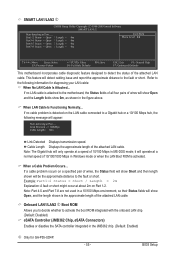
... about 2m on Part 1-2. BIOS Setup This feature will be the approximate distance to a Gigabit hub or a 10/100 Mbps hub, the following information for GA-P55-UD4P. - 55 - If no cable problem is activated. Note: The Gigabit hub will show Open, and the length shown is attached to activate the boot...
... about 2m on Part 1-2. BIOS Setup This feature will be the approximate distance to a Gigabit hub or a 10/100 Mbps hub, the following information for GA-P55-UD4P. - 55 - If no cable problem is activated. Note: The Gigabit hub will show Open, and the length shown is attached to activate the boot...

Manual
Page 61
In case system instability occurs, you may try to load Fail-Safe defaults, which are the safest and most stable BIOS settings for GA-P55-UD4P. - 61 - Always load the Optimized defaults after updating the BIOS or after clearing the CMOS values. The BIOS defaults settings help the system to ...
In case system instability occurs, you may try to load Fail-Safe defaults, which are the safest and most stable BIOS settings for GA-P55-UD4P. - 61 - Always load the Optimized defaults after updating the BIOS or after clearing the CMOS values. The BIOS defaults settings help the system to ...

Manual
Page 62
... but not to make changes to System, you must enter the supervisor password (or user password) at system startup to confirm the password. j Only for GA-P55-UD4P.
... but not to make changes to System, you must enter the supervisor password (or user password) at system startup to confirm the password. j Only for GA-P55-UD4P.
