
Manual
Page 3
... recommend that you set Security Chip to activate the TPM chip. TPM Configuration Procedure To enable the TPM, follow the steps below in the BIOS main menu to display this setting) to back up the encrypted files first. CMOS Setup Utility-Copyright (C) 1984-2009 Award Software Security Chip Configuration Security Chip...
... recommend that you set Security Chip to activate the TPM chip. TPM Configuration Procedure To enable the TPM, follow the steps below in the BIOS main menu to display this setting) to back up the encrypted files first. CMOS Setup Utility-Copyright (C) 1984-2009 Award Software Security Chip Configuration Security Chip...

Manual
Page 4
... the Smart TPM utility altogether. - 4 - Click the Install button on the "Xpress Install" main menu to install it. Some motherboard driver disks include the Smart TPM utility in "Xpress Install." Installing the Infineon TPM Driver Insert the GIGABYTE motherboard driver disk. Installing the Infineon TPM Driver and the Smart TPM Utility Before...
... the Smart TPM utility altogether. - 4 - Click the Install button on the "Xpress Install" main menu to install it. Some motherboard driver disks include the Smart TPM utility in "Xpress Install." Installing the Infineon TPM Driver Insert the GIGABYTE motherboard driver disk. Installing the Infineon TPM Driver and the Smart TPM Utility Before...

Manual
Page 8
... Wizard. Owner Click Advanced mode to continue. - 8 - A-1. 3.2. Follow the on the Infineon Security Platform. Infineon Security Platform Initialization Wizard - Advanced Mode On the Smart TPM main screen, click Advanced mode to configure Security Platform Features (backup including Emergency Recovery, Password Reset, Enhanced Authentication, BitLocker). A.
... Wizard. Owner Click Advanced mode to continue. - 8 - A-1. 3.2. Follow the on the Infineon Security Platform. Infineon Security Platform Initialization Wizard - Advanced Mode On the Smart TPM main screen, click Advanced mode to configure Security Platform Features (backup including Emergency Recovery, Password Reset, Enhanced Authentication, BitLocker). A.
Manual
Page 4
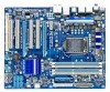
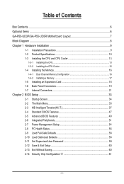
Table of Contents Box Contents...6 Optional Items...6 GA-P55-UD3P/GA-P55-UD3R Motherboard Layout 7 Block Diagram...8 Chapter 1 Hardware Installation 9 1-1 Installation Precautions 9 1-2 Product Specifications 10 1-3 Installing the CPU and CPU Cooler ... Memory 17 1-5 Installing an Expansion Card 18 1-6 Back Panel Connectors 19 1-7 Internal Connectors 21 Chapter 2 BIOS Setup 33 2-1 Startup Screen 34 2-2 The Main Menu 35 2-3 MB Intelligent Tweaker(M.I.T 37 2-4 Standard CMOS Features 47 2-5 Advanced BIOS Features 49 2-6 Integrated Peripherals 51 2-7 Power Management Setup 54 2-8 PC...
Table of Contents Box Contents...6 Optional Items...6 GA-P55-UD3P/GA-P55-UD3R Motherboard Layout 7 Block Diagram...8 Chapter 1 Hardware Installation 9 1-1 Installation Precautions 9 1-2 Product Specifications 10 1-3 Installing the CPU and CPU Cooler ... Memory 17 1-5 Installing an Expansion Card 18 1-6 Back Panel Connectors 19 1-7 Internal Connectors 21 Chapter 2 BIOS Setup 33 2-1 Startup Screen 34 2-2 The Main Menu 35 2-3 MB Intelligent Tweaker(M.I.T 37 2-4 Standard CMOS Features 47 2-5 Advanced BIOS Features 49 2-6 Integrated Peripherals 51 2-7 Power Management Setup 54 2-8 PC...
Manual
Page 11
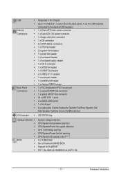
... the Chipset Up to 14 USB 2.0/1.1 ports (10 on the back panel, 4 via the USB brackets connected to the internal USB headers) 1 x 24-pin ATX main power connector 1 x 8-pin ATX 12V power connector 1 x floppy disk drive connector 1 x IDE connector 8 x SATA 3Gb/s connectors 1 x CPU fan header 2 x system fan headers 1 x power fan header...
... the Chipset Up to 14 USB 2.0/1.1 ports (10 on the back panel, 4 via the USB brackets connected to the internal USB headers) 1 x 24-pin ATX main power connector 1 x 8-pin ATX 12V power connector 1 x floppy disk drive connector 1 x IDE connector 8 x SATA 3Gb/s connectors 1 x CPU fan header 2 x system fan headers 1 x power fan header...
Manual
Page 22
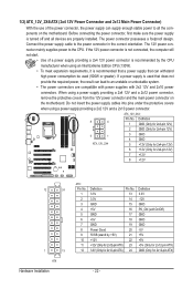
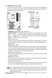
...When using a power supply providing a 2x4 12V and a 2x12 power connector, remove the protective covers from the 12V power connector and the main power connector on the motherboard. Before connecting the power connector, first make sure the power supply is turned off and all the components on... stable power to an unstable or unbootable system. • The power connectors are properly installed. 1/2) ATX_12V_2X4/ATX (2x4 12V Power Connector and 2x12 Main Power Connector) With the use of a power supply providing a 2x4 12V power connector is recommended by +5V) 21 +12V 22 +12V (Only...
...When using a power supply providing a 2x4 12V and a 2x12 power connector, remove the protective covers from the 12V power connector and the main power connector on the motherboard. Before connecting the power connector, first make sure the power supply is turned off and all the components on... stable power to an unstable or unbootable system. • The power connectors are properly installed. 1/2) ATX_12V_2X4/ATX (2x4 12V Power Connector and 2x12 Main Power Connector) With the use of a power supply providing a 2x4 12V power connector is recommended by +5V) 21 +12V 22 +12V (Only...
Manual
Page 26
... startup. Hardware Installation - 26 - The LED is on when the hard drive is detected, the BIOS may differ by issuing a beep code. A front panel module mainly consists of power switch, reset switch, power LED, hard drive activity LED, speaker and etc. Press the reset switch to restart the computer if the...
... startup. Hardware Installation - 26 - The LED is on when the hard drive is detected, the BIOS may differ by issuing a beep code. A front panel module mainly consists of power switch, reset switch, power LED, hard drive activity LED, speaker and etc. Press the reset switch to restart the computer if the...
Manual
Page 33
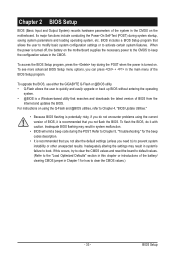
To upgrade the BIOS, use either the GIGABYTE Q-Flash or @BIOS utility. • Q-Flash allows the user to quickly and easily upgrade or back up BIOS without entering the operating system. • @BIOS ..., refer to Chapter 4, "BIOS Update Utilities." • Because BIOS flashing is potentially risky, if you do it is recommended that you can press + in the main menu of the battery/ clearing CMOS jumper in Chapter 1 for the beep codes description. • It is recommended that you not alter the default settings...
To upgrade the BIOS, use either the GIGABYTE Q-Flash or @BIOS utility. • Q-Flash allows the user to quickly and easily upgrade or back up BIOS without entering the operating system. • @BIOS ..., refer to Chapter 4, "BIOS Update Utilities." • Because BIOS flashing is potentially risky, if you do it is recommended that you can press + in the main menu of the battery/ clearing CMOS jumper in Chapter 1 for the beep codes description. • It is recommended that you not alter the default settings...
Manual
Page 35
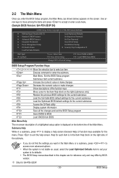
... want in the Main Menu or a submenu, press + to access more advanced options. • When the system is not stable as shown below) appears on the screen. Use arrow keys to move among the items and press to accept or enter a sub-menu. (Sample BIOS Version: GA-P55-UD3P D6) CMOS Setup... Save & Exit Setup Change CPU's Clock & Voltage F11: Save CMOS to BIOS F12: Load CMOS from BIOS Main Menu Help The on-screen description of a highlighted setup option is displayed on the bottom line of function keys available for GA-P55-UD3P. - 35 - Press to exit the help screen (General Help) of the...
... want in the Main Menu or a submenu, press + to access more advanced options. • When the system is not stable as shown below) appears on the screen. Use arrow keys to move among the items and press to accept or enter a sub-menu. (Sample BIOS Version: GA-P55-UD3P D6) CMOS Setup... Save & Exit Setup Change CPU's Clock & Voltage F11: Save CMOS to BIOS F12: Load CMOS from BIOS Main Menu Help The on-screen description of a highlighted setup option is displayed on the bottom line of function keys available for GA-P55-UD3P. - 35 - Press to exit the help screen (General Help) of the...
Manual
Page 36
... you to restrict access to the system and BIOS Setup. BIOS Setup - 36 - The Functions of the and keys (For the Main Menu Only) F11: Save CMOS to BIOS This function allows you to save the current BIOS settings to load the BIOS settings from BIOS... Fail-Safe defaults are factory settings for the most stable, minimal-performance system operations. Load Optimized Defaults Optimized defaults are factory settings for GA-P55-UD3P. First enter the profile name (to erase the default profile name, use the SPACE key) and then press to complete. F12:...
... you to restrict access to the system and BIOS Setup. BIOS Setup - 36 - The Functions of the and keys (For the Main Menu Only) F11: Save CMOS to BIOS This function allows you to save the current BIOS settings to load the BIOS settings from BIOS... Fail-Safe defaults are factory settings for the most stable, minimal-performance system operations. Load Optimized Defaults Optimized defaults are factory settings for GA-P55-UD3P. First enter the profile name (to erase the default profile name, use the SPACE key) and then press to complete. F12:...
Manual
Page 49
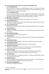
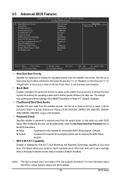
... greater efficiency for entering the operating system and to exit this item, set the password(s) under the Set Supervisor/User Password item in the BIOS Main Menu. This feature allows your hard drive. Use the up or down arrow key to select a hard drive, then press the plus key (or ) or...
... greater efficiency for entering the operating system and to exit this item, set the password(s) under the Set Supervisor/User Password item in the BIOS Main Menu. This feature allows your hard drive. Use the up or down arrow key to select a hard drive, then press the plus key (or ) or...
Manual
Page 60
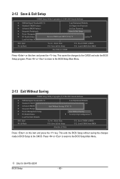
Press or to return to the CMOS. Press or to return to the BIOS Setup Main Menu. 2-13 Exit Without Saving CMOS Setup Utility-Copyright (C) 1984-2009 Award Software MB Intelligent Tweaker(M.I .T.) Load Optimized Defaults Standard CMOS Features Set ... on this item and press the key. This exits the BIOS Setup without saving the changes made in BIOS Setup to the BIOS Setup Main Menu. j Only for GA-P55-UD3P. This saves the changes to the CMOS and exits the BIOS Setup program. BIOS Setup - 60 - 2-12 Save & Exit Setup CMOS Setup Utility...
Press or to return to the CMOS. Press or to return to the BIOS Setup Main Menu. 2-13 Exit Without Saving CMOS Setup Utility-Copyright (C) 1984-2009 Award Software MB Intelligent Tweaker(M.I .T.) Load Optimized Defaults Standard CMOS Features Set ... on this item and press the key. This exits the BIOS Setup without saving the changes made in BIOS Setup to the BIOS Setup Main Menu. j Only for GA-P55-UD3P. This saves the changes to the CMOS and exits the BIOS Setup program. BIOS Setup - 60 - 2-12 Save & Exit Setup CMOS Setup Utility...
Manual
Page 70
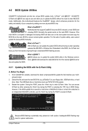
... pressing the key in RAID/AHCI mode or a hard drive attached to enter MS-DOS mode. P55-UD3P D6 . . . . : BIOS Setup : XpressRecovery2 : Boot Menu : Qflash 07/08/2009-P55-7A89RG0JC-00 Because BIOS flashing is saved to a hard drive in BIOS Setup. Restart the system..... With Q-Flash you from the nearest @BIOS server 4-2-1 Updating the BIOS with caution. From GIGABYTE's website, download the latest compressed BIOS update file that support DualBIOS have two BIOS onboard, a main BIOS and a backup BIOS. What is DualBIOS™? site and update the BIOS. Before You...
... pressing the key in RAID/AHCI mode or a hard drive attached to enter MS-DOS mode. P55-UD3P D6 . . . . : BIOS Setup : XpressRecovery2 : Boot Menu : Qflash 07/08/2009-P55-7A89RG0JC-00 Because BIOS flashing is saved to a hard drive in BIOS Setup. Restart the system..... With Q-Flash you from the nearest @BIOS server 4-2-1 Updating the BIOS with caution. From GIGABYTE's website, download the latest compressed BIOS update file that support DualBIOS have two BIOS onboard, a main BIOS and a backup BIOS. What is DualBIOS™? site and update the BIOS. Before You...
Manual
Page 71
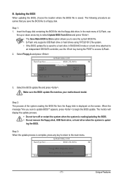
ing the BIOS. Select Floppy A and press . Step 2: The process of Q-Flash, use the key during the POST to the main menu. CoaodpyCMBIOOSS DcoemfapuletteEdn-aPbaless !! Make sure the BIOS update file matches your motherboard model. Step 3: When the update process is displayed on the screen. ... from the floppy disk is complete, press any key to return to access Q-Flash. 2. In the main menu of the system reading the BIOS file from Drive and press . • The Save Main BIOS to Drive option allows you to save the BIOS file to Drive Enter : Run hi:Move ESC...
ing the BIOS. Select Floppy A and press . Step 2: The process of Q-Flash, use the key during the POST to the main menu. CoaodpyCMBIOOSS DcoemfapuletteEdn-aPbaless !! Make sure the BIOS update file matches your motherboard model. Step 3: When the update process is displayed on the screen. ... from the floppy disk is complete, press any key to return to access Q-Flash. 2. In the main menu of the system reading the BIOS file from Drive and press . • The Save Main BIOS to Drive option allows you to save the BIOS file to Drive Enter : Run hi:Move ESC...
Manual
Page 79
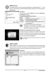
...can quickly create backups of the dates. Unique Features SMART DualBIOS SMART DualBIOS is reached, the oldest backup will be ovewritten. Instructions: In the main menu, click the Config button to launch the SMART DualBIOS utility. Instructions for saving backups (Note 4) • The hard drive must have...partitioned on the right or at different time, select a backup time using the time scroll bar on NTFS file system) in the main and backup BIOS simultaneously, which can record personal passwords and important dates and set reminders of the screen. Click Save to save the...
...can quickly create backups of the dates. Unique Features SMART DualBIOS SMART DualBIOS is reached, the oldest backup will be ovewritten. Instructions: In the main menu, click the Config button to launch the SMART DualBIOS utility. Instructions for saving backups (Note 4) • The hard drive must have...partitioned on the right or at different time, select a backup time using the time scroll bar on NTFS file system) in the main and backup BIOS simultaneously, which can record personal passwords and important dates and set reminders of the screen. Click Save to save the...
Manual
Page 81
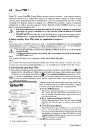
...Previously encrypted files will store the encrypted TPM User Password in the BIOS main menu to display this password because it to -use the Clear Security Chip setting (press + in the system BIOS. 3. 4-7 Smart TPM j GIGABYTE's unique Smart TPM (Trusted Platform Module) supports the industry's most advanced ... to the Bluetooth cell phone or when plugging in sequence: Step 1: As the computer starts, enter the BIOS Setup program. Instructions for GA-P55-UD3P. - 81 - You can access/close your Bluetooth cell phone/USB flash drive as the Smart TPM user key. Create Your Smart TPM...
...Previously encrypted files will store the encrypted TPM User Password in the BIOS main menu to display this password because it to -use the Clear Security Chip setting (press + in the system BIOS. 3. 4-7 Smart TPM j GIGABYTE's unique Smart TPM (Trusted Platform Module) supports the industry's most advanced ... to the Bluetooth cell phone or when plugging in sequence: Step 1: As the computer starts, enter the BIOS Setup program. Instructions for GA-P55-UD3P. - 81 - You can access/close your Bluetooth cell phone/USB flash drive as the Smart TPM user key. Create Your Smart TPM...

Manual
Page 85
... Create RAID Volume in RAID BIOS Enter the RAID BIOS setup utility to configure a RAID array. Create RAID Volume If you press + , the MAIN MENU screen will appear (Figure 3). Recovery Volume Options RAID Volumes : None defined. [ DISK/VOLUME INFORMATION ] Physical Disks : Port Drive Model 0... 111.7GB Type/Status(Vol ID) Non-RAID Disk Non-RAID Disk Press to Non-RAID 4. All Rights Reserved. [ MAIN MENU ] 1. Configuring a RAID array in MAIN MENU and press . Press + to enter Configuration Utility" (Figure 2). Create RAID Volume 2. All Rights Reserved. Delete RAID...
... Create RAID Volume in RAID BIOS Enter the RAID BIOS setup utility to configure a RAID array. Create RAID Volume If you press + , the MAIN MENU screen will appear (Figure 3). Recovery Volume Options RAID Volumes : None defined. [ DISK/VOLUME INFORMATION ] Physical Disks : Port Drive Model 0... 111.7GB Type/Status(Vol ID) Non-RAID Disk Non-RAID Disk Press to Non-RAID 4. All Rights Reserved. [ MAIN MENU ] 1. Configuring a RAID array in MAIN MENU and press . Press + to enter Configuration Utility" (Figure 2). Create RAID Volume 2. All Rights Reserved. Delete RAID...
Manual
Page 87
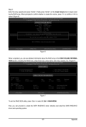
Step 5: Enter the array capacity and press . Intel(R) Matrix Storage Manager option ROM v8.9.0.1023 PCH-D wRAID5 Copyright(C) 2003-09 Intel Corporation. All Rights Reserved. [ MAIN MENU ] 1. Recovery Volume Options RAID Volumes : ID Name 0 Volume0 [ DISK/VOLUME INFORMATION ] Level RAID0(Stripe) Strip 128KB Size 223.6GB Status Normal Bootable Yes Physical ... : N/A Create Volume WARNING : ALL DATA ON SELECTED DISKS WILL BE LOST. [ HELP ] Are you sure you can see detailed information about the RAID array in MAIN MENU.
Step 5: Enter the array capacity and press . Intel(R) Matrix Storage Manager option ROM v8.9.0.1023 PCH-D wRAID5 Copyright(C) 2003-09 Intel Corporation. All Rights Reserved. [ MAIN MENU ] 1. Recovery Volume Options RAID Volumes : ID Name 0 Volume0 [ DISK/VOLUME INFORMATION ] Level RAID0(Stripe) Strip 128KB Size 223.6GB Status Normal Bootable Yes Physical ... : N/A Create Volume WARNING : ALL DATA ON SELECTED DISKS WILL BE LOST. [ HELP ] Are you sure you can see detailed information about the RAID array in MAIN MENU.

Manual
Page 88
... Figure 9 - 88 - [ENTER]-Select A recovery volume and a RAID array cannot co-exist in the system at the same time, that is hidden. All Rights Reserved. [ MAIN MENU ] 1. Intel(R) Matrix Storage Manager option ROM v8.9.0.1023 PCH-D wRAID5 Copyright(C) 2003-09 Intel Corporation. Recovery: Copies data between a master and a recovery disk. Create... a recovery volume, you begin: • The recovery drive must have equal or greater capacity than the master drive. • A recovery volume can be riewed in MAIN MENU and press (Figure 8).
... Figure 9 - 88 - [ENTER]-Select A recovery volume and a RAID array cannot co-exist in the system at the same time, that is hidden. All Rights Reserved. [ MAIN MENU ] 1. Intel(R) Matrix Storage Manager option ROM v8.9.0.1023 PCH-D wRAID5 Copyright(C) 2003-09 Intel Corporation. Recovery: Copies data between a master and a recovery disk. Create... a recovery volume, you begin: • The recovery drive must have equal or greater capacity than the master drive. • A recovery volume can be riewed in MAIN MENU and press (Figure 8).

Manual
Page 90
... your selection (Figure 12), press to confirm or to be deleted and press . Delete RAID Volume To delete a RAID array, select Delete RAID Volume in MAIN MENU and press .
... your selection (Figure 12), press to confirm or to be deleted and press . Delete RAID Volume To delete a RAID array, select Delete RAID Volume in MAIN MENU and press .