Manual
Page 4
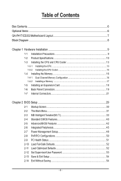
Table of Contents Box Contents...6 Optional Items...6 GA-P41T-ES3G Motherboard Layout 7 Block Diagram...8 Chapter 1 Hardware Installation 9 1-1 Installation Precautions 9 1-2 Product Specifications 10 1-3 Installing the CPU and CPU Cooler 13 1-3-1 Installing the CPU 13 1-3-2 Installing the CPU Cooler 15 1-4 Installing the Memory 16 1-4-1 Dual Channel Memory Configuration 16 1-4-2 Installing a Memory 17 1-5 Installing an Expansion Card 18 1-6 Back Panel Connectors...
Table of Contents Box Contents...6 Optional Items...6 GA-P41T-ES3G Motherboard Layout 7 Block Diagram...8 Chapter 1 Hardware Installation 9 1-1 Installation Precautions 9 1-2 Product Specifications 10 1-3 Installing the CPU and CPU Cooler 13 1-3-1 Installing the CPU 13 1-3-2 Installing the CPU Cooler 15 1-4 Installing the Memory 16 1-4-1 Dual Channel Memory Configuration 16 1-4-2 Installing a Memory 17 1-5 Installing an Expansion Card 18 1-6 Back Panel Connectors...

Manual
Page 8
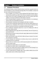
Block Diagram PCIe CLK (100 MHz) 1 PCI Express x16 x16 PCI Express x16 3 PCI Express x1 PCIe CLK (100 MHz) x1 x1 x1 PCI Express Bus x1 RTL8111D RJ45 LAN PCI Bus LGA775 Processor CPU CLK+/(333/266/200 MHz) Host Interface Intel® G41 DDR3 1333(O.C.)/1066/800 MHz Dual Channel Memory MCH CLK (333/266/200 MHz) Intel® ICH7 CODEC Dual BIOS ATA-100/66/33 IDE Channel 4 SATA 3Gb/s 8 USB 2.0/1.1 IT8718 Floppy LPT COM Port PS/2 KB/Mouse MIC (Center/Subwoofer Speaker Out) Line-Out (Front Speaker Out) Line-In (Rear Speaker Out) S/PDIF Out 3 PCI PCI CLK (33 MHz) - 8 -
Block Diagram PCIe CLK (100 MHz) 1 PCI Express x16 x16 PCI Express x16 3 PCI Express x1 PCIe CLK (100 MHz) x1 x1 x1 PCI Express Bus x1 RTL8111D RJ45 LAN PCI Bus LGA775 Processor CPU CLK+/(333/266/200 MHz) Host Interface Intel® G41 DDR3 1333(O.C.)/1066/800 MHz Dual Channel Memory MCH CLK (333/266/200 MHz) Intel® ICH7 CODEC Dual BIOS ATA-100/66/33 IDE Channel 4 SATA 3Gb/s 8 USB 2.0/1.1 IT8718 Floppy LPT COM Port PS/2 KB/Mouse MIC (Center/Subwoofer Speaker Out) Line-Out (Front Speaker Out) Line-In (Rear Speaker Out) S/PDIF Out 3 PCI PCI CLK (33 MHz) - 8 -
Manual
Page 9
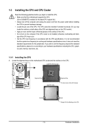
...; Do not place the computer system in a high-temperature environment. • Turning on the computer power during the installation process can become damaged as a motherboard, CPU or memory. Hardware Installation ponents such as a result of the product, please consult a certified computer technician. - 9 - Prior to installation, carefully read the user's manual and...
...; Do not place the computer system in a high-temperature environment. • Turning on the computer power during the installation process can become damaged as a motherboard, CPU or memory. Hardware Installation ponents such as a result of the product, please consult a certified computer technician. - 9 - Prior to installation, carefully read the user's manual and...

Manual
Page 10
...Intel® Pentium® processor/Intel® Celeron® processor in the LGA775 package (Go to GIGABYTE's website for the latest CPU support list.) L2 cache varies with CPU Front Side Bus w 1333/1066/800 MHz FSB Chipset Memory Audio w North Bridge: Intel®...channel memory architecture Support for DDR3 1333(O.C.)/1066/800 MHz memory modules Support for non-ECC memory modules (Go to GIGABYTE's website for the latest memory support list.) Realtek ALC888 codec High Definition Audio 2/4/5.1/7.1-channel(Note 1) &#...
...Intel® Pentium® processor/Intel® Celeron® processor in the LGA775 package (Go to GIGABYTE's website for the latest CPU support list.) L2 cache varies with CPU Front Side Bus w 1333/1066/800 MHz FSB Chipset Memory Audio w North Bridge: Intel®...channel memory architecture Support for DDR3 1333(O.C.)/1066/800 MHz memory modules Support for non-ECC memory modules (Go to GIGABYTE's website for the latest memory support list.) Realtek ALC888 codec High Definition Audio 2/4/5.1/7.1-channel(Note 1) &#...

Manual
Page 11
...ATX main power connector w 1 x 4-pin ATX 12V power connector w 1 x floppy disk drive connector w 1 x IDE connector w 4 x SATA 3Gb/s connectors w 1 x CPU fan header w 2 x system fan headers w 1 x power fan header w 1 x front panel header w 1 x front panel audio header w 1 x CD In connector w...Monitor w w w w w w BIOS w w w w System voltage detection CPU/System temperature detection CPU/System/Power fan speed detection CPU overheating warning CPU/System/Power fan fail warning CPU fan speed control (Note 2) 2 x 8 Mbit flash Use of licensed AWARD ...
...ATX main power connector w 1 x 4-pin ATX 12V power connector w 1 x floppy disk drive connector w 1 x IDE connector w 4 x SATA 3Gb/s connectors w 1 x CPU fan header w 2 x system fan headers w 1 x power fan header w 1 x front panel header w 1 x front panel audio header w 1 x CD In connector w...Monitor w w w w w w BIOS w w w w System voltage detection CPU/System temperature detection CPU/System/Power fan speed detection CPU overheating warning CPU/System/Power fan fail warning CPU fan speed control (Note 2) 2 x 8 Mbit flash Use of licensed AWARD ...

Manual
Page 12
... an HD front panel audio module and enable the multi-channel audio feature through the audio driver. (Note 2) Whether the CPU fan speed control function is supported will depend on the CPU cooler you install. (Note 3) Available functions in EasyTune may differ by motherboard model. (Note 4) Due to the hardware limitation, you...
... an HD front panel audio module and enable the multi-channel audio feature through the audio driver. (Note 2) Whether the CPU fan speed control function is supported will depend on the CPU cooler you install. (Note 3) Available functions in EasyTune may differ by motherboard model. (Note 4) Due to the hardware limitation, you...
Manual
Page 13
... is not installed, otherwise overheating and dam- Locate the alignment keys on the motherboard CPU socket and the notches on the computer if the CPU cooler is not recommended that the motherboard supports the CPU. (Go to GIGABYTE's website for the peripherals. Hardware Installation If you wish to set beyond the standard specifications, please...
... is not installed, otherwise overheating and dam- Locate the alignment keys on the motherboard CPU socket and the notches on the computer if the CPU cooler is not recommended that the motherboard supports the CPU. (Go to GIGABYTE's website for the peripherals. Hardware Installation If you wish to set beyond the standard specifications, please...

Manual
Page 14
... power outlet to prevent damage to the CPU. Step 5: Once the CPU is not installed.) Step 4: Hold the CPU with the socket alignment keys) and gently insert the CPU into its locked position. CPU Socket Lever Step 1: Completely raise the CPU socket lever. Align the CPU pin one marking (triangle) with the ...pin one corner of the CPU socket (or you may align the CPU notches with your thumb and index fingers. Before installing the CPU, make sure to correctly install the CPU into the motherboard CPU socket. Follow the steps below to turn off the computer ...
... power outlet to prevent damage to the CPU. Step 5: Once the CPU is not installed.) Step 4: Hold the CPU with the socket alignment keys) and gently insert the CPU into its locked position. CPU Socket Lever Step 1: Completely raise the CPU socket lever. Align the CPU pin one marking (triangle) with the ...pin one corner of the CPU socket (or you may align the CPU notches with your thumb and index fingers. Before installing the CPU, make sure to correctly install the CPU into the motherboard CPU socket. Follow the steps below to turn off the computer ...
Manual
Page 15
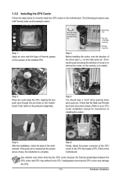
...Turning the push pin along the direction of the motherboard. Check that the Male and Female push pins are joined closely. (Refer to your CPU cooler installation manual for instructions on installing the cooler.) Step 5: After the installation, check the back of arrow is to remove the cooler,... on the contrary, is complete. Step 6: Finally, attach the power connector of the installed CPU. Push down each push pin. Hardware Installation Step 4: You should hear a "click" when pushing down on the push pins diagonally. If the ...
...Turning the push pin along the direction of the motherboard. Check that the Male and Female push pins are joined closely. (Refer to your CPU cooler installation manual for instructions on installing the cooler.) Step 5: After the installation, check the back of arrow is to remove the cooler,... on the contrary, is complete. Step 6: Finally, attach the power connector of the installed CPU. Push down each push pin. Hardware Installation Step 4: You should hear a "click" when pushing down on the push pins diagonally. If the ...

Manual
Page 22
Connect the power supply cable to the CPU. If a power supply is used that can withstand high power consumption be used (500W or greater). Before connecting the power connector, first make sure the ...
Connect the power supply cable to the CPU. If a power supply is used that can withstand high power consumption be used (500W or greater). Before connecting the power connector, first make sure the ...

Manual
Page 23
...supported are not configuration jumper blocks. Definition 1 GND 2 +12V 3 Sense 4 Speed Control SYS_FAN1/SYS_FAN2: Pin No. The motherboard supports CPU fan speed control, which requires the use of the connector and the floppy disk drive cable. Most fan headers possess a foolproof insertion design... 1 PWR_FAN CPU_FAN: Pin No. Overheating may result in the correct orientation (the black connector wire is used to locate pin 1 of a CPU fan with fan speed control design. Definition 1 GND 2 +12V 3 Sense PWR_FAN: Pin No. 3/4/5) CPU_FAN/SYS_FAN1/SYS_FAN2/PWR_FAN (Fan Headers) The motherboard...
...supported are not configuration jumper blocks. Definition 1 GND 2 +12V 3 Sense 4 Speed Control SYS_FAN1/SYS_FAN2: Pin No. The motherboard supports CPU fan speed control, which requires the use of the connector and the floppy disk drive cable. Most fan headers possess a foolproof insertion design... 1 PWR_FAN CPU_FAN: Pin No. Overheating may result in the correct orientation (the black connector wire is used to locate pin 1 of a CPU fan with fan speed control design. Definition 1 GND 2 +12V 3 Sense PWR_FAN: Pin No. 3/4/5) CPU_FAN/SYS_FAN1/SYS_FAN2/PWR_FAN (Fan Headers) The motherboard...

Manual
Page 31
... Optimized Defaults Set Supervisor Password Set User Password Save & Exit Setup Exit Without Saving ESC: Quit F8: Q-Flash Select Item F10: Save & Exit Setup Change CPU's Clock & Voltage F11: Save CMOS to BIOS F12: Load CMOS from BIOS Main Menu Help The on-screen description of a highlighted setup option is in...
... Optimized Defaults Set Supervisor Password Set User Password Save & Exit Setup Exit Without Saving ESC: Quit F8: Q-Flash Select Item F10: Save & Exit Setup Change CPU's Clock & Voltage F11: Save CMOS to BIOS F12: Load CMOS from BIOS Main Menu Help The on-screen description of a highlighted setup option is in...

Manual
Page 32
...menu to configure the system's PCI & PnP resources. PC Health Status Use this function to load the BIOS settings from BIOS If your CPU, memory, etc. Standard CMOS Features Use this menu to configure the system time and date, hard drive types, floppy disk drive types,... that stop the system boot, etc. Advanced BIOS Features Use this menu to configure the device boot order, advanced features available on the CPU, and the primary display adapter. Integrated Peripherals Use this menu to configure all peripheral devices, such as IDE, SATA, USB, integrated audio...
...menu to configure the system's PCI & PnP resources. PC Health Status Use this function to load the BIOS settings from BIOS If your CPU, memory, etc. Standard CMOS Features Use this menu to configure the system time and date, hard drive types, floppy disk drive types,... that stop the system boot, etc. Advanced BIOS Features Use this menu to configure the device boot order, advanced features available on the CPU, and the primary display adapter. Integrated Peripherals Use this menu to configure all peripheral devices, such as IDE, SATA, USB, integrated audio...

Manual
Page 33
... Auto Auto [Press Enter] Item Help Menu Level ******** Mother Board Voltage Control ******** Voltage Types Normal Current >>> CPU CPU Vcore 1.17500V [Auto] CPU Termination 1.200V [Auto] CPU Reference 0.805V [Auto] >>> MCH/ICH MCH Core 1.200V [Auto] ICH I/O 1.550 >>> DRAM DRAM Voltage 1.500V ... stably with the overclock/overvoltage settings you made is for advanced users only and we recommend you install a CPU that supports this occurs, clear the CMOS values and reset the board to boot. Incorrectly doing overclock/overvoltage ...
... Auto Auto [Press Enter] Item Help Menu Level ******** Mother Board Voltage Control ******** Voltage Types Normal Current >>> CPU CPU Vcore 1.17500V [Auto] CPU Termination 1.200V [Auto] CPU Reference 0.805V [Auto] >>> MCH/ICH MCH Core 1.200V [Auto] ICH I/O 1.550 >>> DRAM DRAM Voltage 1.500V ... stably with the overclock/overvoltage settings you made is for advanced users only and we recommend you install a CPU that supports this occurs, clear the CMOS values and reset the board to boot. Incorrectly doing overclock/overvoltage ...

Manual
Page 34
...: Auto (default), Fast, Turbo. The item is present only if a CPU with unlocked clock ratio is from 90 MHz to automatically set the CPU host frequency. CPU Frequency Displays the current operating CPU frequency. ******** Clock Chip Control Standard Clock Control CPU Host Clock Control Enables or disables the control of the graphics chip... and memory. This item is configurable only if the CPU Host Clock Control option is from 100 MHz to be set the PCIe clock frequency. Important: It is installed. BIOS Setup - 34 - ...
...: Auto (default), Fast, Turbo. The item is present only if a CPU with unlocked clock ratio is from 90 MHz to automatically set the CPU host frequency. CPU Frequency Displays the current operating CPU frequency. ******** Clock Chip Control Standard Clock Control CPU Host Clock Control Enables or disables the control of the graphics chip... and memory. This item is configurable only if the CPU Host Clock Control option is from 100 MHz to be set the PCIe clock frequency. Important: It is installed. BIOS Setup - 34 - ...

Manual
Page 35
...Manual. >>>>> Standard Timing Control CAS Latency Time Options are : Auto (default), 200MHz, 266MHz, 333MHz. BIOS Setup tRCD Options are dependent on CPU FSB and the (G)MCH Frequency Latch settings. Extreme Lets the system operate at its good performance level. Options are : Auto (default), 1~15....below to memory SPD data. (Default: Auto) Memory Frequency (Mhz) The first memory frequency value is automatically adjusted according to the CPU Host Frequency (Mhz) and System Memory Multiplier settings. System Memory Multiplier (SPD) Allows you to fix the chipset frequency at three ...
...Manual. >>>>> Standard Timing Control CAS Latency Time Options are : Auto (default), 200MHz, 266MHz, 333MHz. BIOS Setup tRCD Options are dependent on CPU FSB and the (G)MCH Frequency Latch settings. Extreme Lets the system operate at its good performance level. Options are : Auto (default), 1~15....below to memory SPD data. (Default: Auto) Memory Frequency (Mhz) The first memory frequency value is automatically adjusted according to the CPU Host Frequency (Mhz) and System Memory Multiplier settings. System Memory Multiplier (SPD) Allows you to fix the chipset frequency at three ...

Manual
Page 39
ICH I/O The default is Auto. >>> DRAM DRAM Voltage The default is Auto. CPU Reference The default is Auto. >>> MCH/ICH MCH Core The default is Auto. - 39 - CPU Termination The default is Auto. Ctrl Driving Pull-Down Level Options are : Auto (default), +8~-7. Clk Driving Pull-Down Level Options are: Auto (default), +8~-7. ******** Mother Board Voltage Control CPU CPU Vcore The default is Auto. BIOS Setup Cmd Driving Pull-Down Level Options are : Auto (default), +8~-7.
ICH I/O The default is Auto. >>> DRAM DRAM Voltage The default is Auto. CPU Reference The default is Auto. >>> MCH/ICH MCH Core The default is Auto. - 39 - CPU Termination The default is Auto. Ctrl Driving Pull-Down Level Options are : Auto (default), +8~-7. Clk Driving Pull-Down Level Options are: Auto (default), +8~-7. ******** Mother Board Voltage Control CPU CPU Vcore The default is Auto. BIOS Setup Cmd Driving Pull-Down Level Options are : Auto (default), +8~-7.

Manual
Page 42
... only required for entering the BIOS Setup program. (Default) System A password is required every time the system boots, or only when you install a CPU that supports this item, set the password(s) under the Set Supervisor/User Password item in the BIOS Main Menu. 2-5 Advanced BIOS Features CMOS Setup Utility...Options are: Floppy, LS120, Hard Disk, CDROM, ZIP, USB-FDD, USB-ZIP, USB-CDROM, USB-HDD, Legacy LAN, Disabled. BIOS Setup - 42 - Capability CPU Multi-Threading (Note) Limit CPUID Max. Quick Boot Enables or disables the quick boot function to exit this menu when finished.
... only required for entering the BIOS Setup program. (Default) System A password is required every time the system boots, or only when you install a CPU that supports this item, set the password(s) under the Set Supervisor/User Password item in the BIOS Main Menu. 2-5 Advanced BIOS Features CMOS Setup Utility...Options are: Floppy, LS120, Hard Disk, CDROM, ZIP, USB-FDD, USB-ZIP, USB-CDROM, USB-HDD, Legacy LAN, Disabled. BIOS Setup - 42 - Capability CPU Multi-Threading (Note) Limit CPUID Max. Quick Boot Enables or disables the quick boot function to exit this menu when finished.

Manual
Page 43
... its supporting software and system. (Default: Enabled) CPU Enhanced Halt (C1E) (Note) Enables or disables Intel CPU Enhanced Halt (C1E) function, a CPU power-saving function in independent partitions. When enabled, the CPU core frequency and voltage will allow a platform to ...) This item is enabled. (Default: Disabled) CPU Thermal Monitor 2 (TM2) (Note) Enables or disables Intel CPU Thermal Monitor (TM2) function, a CPU overheating protection function. CPU Multi-Threading (Note) Allows you to determine whether to enable all CPU cores and multi-threading capability. (Default) Disabled ...
... its supporting software and system. (Default: Enabled) CPU Enhanced Halt (C1E) (Note) Enables or disables Intel CPU Enhanced Halt (C1E) function, a CPU power-saving function in independent partitions. When enabled, the CPU core frequency and voltage will allow a platform to ...) This item is enabled. (Default: Disabled) CPU Thermal Monitor 2 (TM2) (Note) Enables or disables Intel CPU Thermal Monitor (TM2) function, a CPU overheating protection function. CPU Multi-Threading (Note) Allows you to determine whether to enable all CPU cores and multi-threading capability. (Default) Disabled ...

Manual
Page 51
...Opened field will show "No" at different speed according to the CPU temperature. When CPU temperature exceeds the threshold, BIOS will show "No". Current CPU/SYSTEM/POWER FAN Speed (RPM) Displays current CPU/system/power fan speed. Options are: Disabled (default), 60oC/140oF,... Opened Vcore DDR15V +3.3V +12V Current System Temperature Current CPU Temperature Current CPU FAN Speed Current SYSTEM FAN1 Speed Current SYSTEM FAN2 Speed Current POWER FAN Speed CPU Warning Temperature CPU FAN Fail Warning SYSTEM FAN1 Fail Warning SYSTEM FAN2 Fail ...
...Opened field will show "No" at different speed according to the CPU temperature. When CPU temperature exceeds the threshold, BIOS will show "No". Current CPU/SYSTEM/POWER FAN Speed (RPM) Displays current CPU/system/power fan speed. Options are: Disabled (default), 60oC/140oF,... Opened Vcore DDR15V +3.3V +12V Current System Temperature Current CPU Temperature Current CPU FAN Speed Current SYSTEM FAN1 Speed Current SYSTEM FAN2 Speed Current POWER FAN Speed CPU Warning Temperature CPU FAN Fail Warning SYSTEM FAN1 Fail Warning SYSTEM FAN2 Fail ...


