
Manual
Page 4
Table of Contents Box Contents ...6 OptionalItems ...6 GA-P35C-DS3R/DS3/S3 Motherboard Layout 7 Block Diagram ...8 Chapter 1 Hardware Installation 9 1-1 Installation Precautions 9 1-2 Product Specifications 10 1-3 Installing the CPU and CPU Cooler 13 1-3-1 Installing the CPU 13 1-3-2 Installing the CPU Cooler 15 1-4 Installing the Memory 16 1-4-1 Dual Channel Memory Configuration 16 1-4-2 Installing a Memory 17 1-5 Installing an Expansion Card 18 1-6 Installing the...
Table of Contents Box Contents ...6 OptionalItems ...6 GA-P35C-DS3R/DS3/S3 Motherboard Layout 7 Block Diagram ...8 Chapter 1 Hardware Installation 9 1-1 Installation Precautions 9 1-2 Product Specifications 10 1-3 Installing the CPU and CPU Cooler 13 1-3-1 Installing the CPU 13 1-3-2 Installing the CPU Cooler 15 1-4 Installing the Memory 16 1-4-1 Dual Channel Memory Configuration 16 1-4-2 Installing a Memory 17 1-5 Installing an Expansion Card 18 1-6 Installing the...
Manual
Page 8
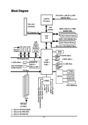
Only for GA-P35C-S3. - 8 - Only for GA-P35C-DS3. Block Diagram PCIe CLK (100 MHz) PCI Express x16 LAN RJ45 PCIe CLK (100 MHz) Realtek 8111B x1 x1 x1 x1 PCI Express Bus 2 SATA 3Gb/s ATA-133/100/66/ 33 IDE Channel GIGABYTE SATA2 / JMicron 368 ...PCI Bus LGA775 Processor CPU CLK+/- (400 (O.C.)/333/ 266/200 MHz) Host Interface DDR2 1200 (O.C.)/1066/ 800/667 MHz Intel® Dual Channel Memory P35 DDR3 1333/1066/800 MHz Dual Channel Memory MCH CLK (333...Out Line-In SPDIF In SPDIF Out 3 PCI PCI CLK (33 MHz) Only for GA-P35C-DS3R.
Only for GA-P35C-S3. - 8 - Only for GA-P35C-DS3. Block Diagram PCIe CLK (100 MHz) PCI Express x16 LAN RJ45 PCIe CLK (100 MHz) Realtek 8111B x1 x1 x1 x1 PCI Express Bus 2 SATA 3Gb/s ATA-133/100/66/ 33 IDE Channel GIGABYTE SATA2 / JMicron 368 ...PCI Bus LGA775 Processor CPU CLK+/- (400 (O.C.)/333/ 266/200 MHz) Host Interface DDR2 1200 (O.C.)/1066/ 800/667 MHz Intel® Dual Channel Memory P35 DDR3 1333/1066/800 MHz Dual Channel Memory MCH CLK (333...Out Line-In SPDIF In SPDIF Out 3 PCI PCI CLK (33 MHz) Only for GA-P35C-DS3R.
Manual
Page 10
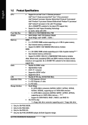
Only for GA-P35C-S3. Only for GA-P35C-DS3. "*" Only the GA-P35C-DS3R/DS3 adopts All-Solid Capacitor design. GA-P35C-DS3R/DS3/S3 Motherboard - 10 - Support for SATA RAID 0, RAID 1, RAID 5, and RAID 10 Š iTE IT8718 chip: - 1 x floppy disk drive connector supporting up to 4 SATA 3Gb/s devices (Note 2) - Go to GIGABYTE's website for the latest memory support list.) Š Realtek ALC889A...
Only for GA-P35C-S3. Only for GA-P35C-DS3. "*" Only the GA-P35C-DS3R/DS3 adopts All-Solid Capacitor design. GA-P35C-DS3R/DS3/S3 Motherboard - 10 - Support for SATA RAID 0, RAID 1, RAID 5, and RAID 10 Š iTE IT8718 chip: - 1 x floppy disk drive connector supporting up to 4 SATA 3Gb/s devices (Note 2) - Go to GIGABYTE's website for the latest memory support list.) Š Realtek ALC889A...
Manual
Page 12
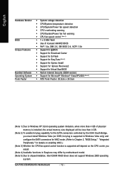
GA-P35C-DS3R/DS3/S3 Motherboard - 12 - English Hardware Monitor BIOS Unique Features Bundled Software Operating System Form Factor Š System voltage detection Š CPU/System temperature detection Š CPU/...; ATX Form Factor; 30.5cm x 24.5cm (Note 1) Due to Windows XP 32-bit operating system limitation, when more than 4 GB of physical memory is installed, the actual memory size displayed will be less than 4 GB. (Note 2) To enable hot plug capability for the SATA connectors controlled by the ICH9 South Bridge...
GA-P35C-DS3R/DS3/S3 Motherboard - 12 - English Hardware Monitor BIOS Unique Features Bundled Software Operating System Form Factor Š System voltage detection Š CPU/System temperature detection Š CPU/...; ATX Form Factor; 30.5cm x 24.5cm (Note 1) Due to Windows XP 32-bit operating system limitation, when more than 4 GB of physical memory is installed, the actual memory size displayed will be less than 4 GB. (Note 2) To enable hot plug capability for the SATA connectors controlled by the ICH9 South Bridge...
Manual
Page 16
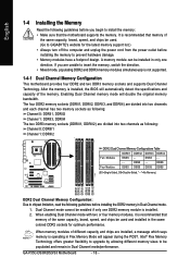
... DDRII1 DDRII2 DDRII3 DDRII4 Two Modules DS/SS - - GA-P35C-DS3R/DS3/S3 Motherboard - 16 - English 1-4 Installing the Memory Read the following guidelines before you are unable to insert the memory, switch the direction. • Mixed mode, populating DDR2 and DDR3 memory modules simultaneously is not supported. 1-4-1 Dual Channel Memory Configuration This motherboard provides four DDR2 and two...
... DDRII1 DDRII2 DDRII3 DDRII4 Two Modules DS/SS - - GA-P35C-DS3R/DS3/S3 Motherboard - 16 - English 1-4 Installing the Memory Read the following guidelines before you are unable to insert the memory, switch the direction. • Mixed mode, populating DDR2 and DDR3 memory modules simultaneously is not supported. 1-4-1 Dual Channel Memory Configuration This motherboard provides four DDR2 and two...

Manual
Page 38
... confirmation message will exit BIOS Setup. (Pressing can also carry out this task.) GA-P35C-DS3R/DS3/S3 Motherboard - 38 - Pressing to the system and BIOS Setup. You can create up to load the BIOS settings from BIOS If your CPU, memory, etc. „ Load Fail-Safe Defaults Fail-Safe defaults are factory settings for...
... confirmation message will exit BIOS Setup. (Pressing can also carry out this task.) GA-P35C-DS3R/DS3/S3 Motherboard - 38 - Pressing to the system and BIOS Setup. You can create up to load the BIOS settings from BIOS If your CPU, memory, etc. „ Load Fail-Safe Defaults Fail-Safe defaults are factory settings for...

Manual
Page 39
...system time. Select the desired field and use the up arrow or down arrow key to set the time. For example, 1 p.m. Only for GA-P35C-DS3R. - 39 - IDE Channel 0/1 Master/Slave IDE HDD Auto-Detection Press to set the date. BIOS Setup Select the desired field and use ... F5: Previous Values +/-/PU/PD: Value F10: Save F6: Fail-Safe Default ESC: Exit F1: General Help F7: Optimized Defaults Base Memory Extended Memory Total Memory CMOS Setup Utility-Copyright (C) 1984-2007 Award Software Standard CMOS Features 640K 511M 512M Item Help Menu Level` KLJI: Move Enter: Select F5...
...system time. Select the desired field and use the up arrow or down arrow key to set the time. For example, 1 p.m. Only for GA-P35C-DS3R. - 39 - IDE Channel 0/1 Master/Slave IDE HDD Auto-Detection Press to set the date. BIOS Setup Select the desired field and use ... F5: Previous Values +/-/PU/PD: Value F10: Save F6: Fail-Safe Default ESC: Exit F1: General Help F7: Optimized Defaults Base Memory Extended Memory Total Memory CMOS Setup Utility-Copyright (C) 1984-2007 Award Software Standard CMOS Features 640K 511M 512M Item Help Menu Level` KLJI: Move Enter: Select F5...

Manual
Page 40
...Cylinder Number of extended memory. Floppy 3 Mode Support Allows you to manually enter the specifications of the hard drive when the hard drive access mode is 3-mode floppy disk drive, a Japanese standard floppy disk drive. Options are : Auto (default), Large. GA-P35C-DS3R/DS3/S3 Motherboard - 40 - ...boot will not stop for a floppy disk drive error but it will stop for GA-P35C-DS3R. Memory These fields are read-only and are : Auto (default), CHS, LBA, Large. Base Memory Also called conventional memory. Typically, 640 KB will not stop for a keyboard or a floppy disk ...
...Cylinder Number of extended memory. Floppy 3 Mode Support Allows you to manually enter the specifications of the hard drive when the hard drive access mode is 3-mode floppy disk drive, a Japanese standard floppy disk drive. Options are : Auto (default), Large. GA-P35C-DS3R/DS3/S3 Motherboard - 40 - ...boot will not stop for a floppy disk drive error but it will stop for GA-P35C-DS3R. Memory These fields are read-only and are : Auto (default), CHS, LBA, Large. Base Memory Also called conventional memory. Typically, 640 KB will not stop for a keyboard or a floppy disk ...

Manual
Page 42
... to display the GIGABYTE Logo at system startup. When enabled, the CPU core frequency and voltage will be reduced during system halt state to Disabled for legacy operating system such as Windows NT4.0. (Default: Disabled) No-Execute Memory Protect (Note) Enables or disables Intel® Execute Disable Bit function. GA-P35C-DS3R/DS3/S3 Motherboard - 42...
... to display the GIGABYTE Logo at system startup. When enabled, the CPU core frequency and voltage will be reduced during system halt state to Disabled for legacy operating system such as Windows NT4.0. (Default: Disabled) No-Execute Memory Protect (Note) Enables or disables Intel® Execute Disable Bit function. GA-P35C-DS3R/DS3/S3 Motherboard - 42...
Manual
Page 48
Note: When using this item. To turn on the system. GA-P35C-DS3R/DS3/S3 Motherboard - 48 - Note: To use this function. (Default) Double Click Double click on left button on the PS/2 mouse to turn on the 5VSB lead. ... : Turn on the system at a desired time. (Default: Disabled) If enabled, set to select the HPET mode for your Windows® Vista® operating system. Memory The system returns to clear the password settings. When prompted for Windows® Vista® operating system. (Default: Enabled) HPET Mode (Note) Allows you need...
Note: When using this item. To turn on the system. GA-P35C-DS3R/DS3/S3 Motherboard - 48 - Note: To use this function. (Default) Double Click Double click on left button on the PS/2 mouse to turn on the 5VSB lead. ... : Turn on the system at a desired time. (Default: Disabled) If enabled, set to select the HPET mode for your Windows® Vista® operating system. Memory The system returns to clear the password settings. When prompted for Windows® Vista® operating system. (Default: Enabled) HPET Mode (Note) Allows you need...
Manual
Page 52
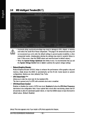
...Clock Ratio (Note) CPU Host Clock Control x CPU Host Frequency (Mhz) PCI Express Frequency (Mhz) C.I.A. 2 Performance Enhance System Memory Multiplier (SPD) Memory Frequency (Mhz) 667 High Speed DRAM DLL Settings ******** System Voltage Optimized System Voltage Control DDR2/DDR3 OverVoltage Control PCI-E OverVoltage Control ...please wait for 20 seconds to allow the CPU Host Frequency item below to boot. Enabled will allow for the installed CPU. GA-P35C-DS3R/DS3/S3 Motherboard - 52 - If this feature. Options are: Auto (default), Fast, Turbo. CPU Host Clock Control Enables or disables ...
...Clock Ratio (Note) CPU Host Clock Control x CPU Host Frequency (Mhz) PCI Express Frequency (Mhz) C.I.A. 2 Performance Enhance System Memory Multiplier (SPD) Memory Frequency (Mhz) 667 High Speed DRAM DLL Settings ******** System Voltage Optimized System Voltage Control DDR2/DDR3 OverVoltage Control PCI-E OverVoltage Control ...please wait for 20 seconds to allow the CPU Host Frequency item below to boot. Enabled will allow for the installed CPU. GA-P35C-DS3R/DS3/S3 Motherboard - 52 - If this feature. Options are: Auto (default), Fast, Turbo. CPU Host Clock Control Enables or disables ...
Manual
Page 54
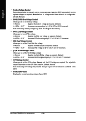
...Default) +0.1V ~ +0.3V Increases North Bridge voltage by 0.1V to 0.3V at 0.1V increment. Auto lets BIOS automatically set memory voltage. FSB OverVoltage Control Allows you to set the Front Side Bus voltage. Normal CPU Vcore Displays the normal operating voltage of ... system voltages. Normal Supplies the PCIe bus voltage as required. English System Voltage Control Determines whether to manually set PCIe voltage. GA-P35C-DS3R/DS3/S3 Motherboard - 54 - Normal Supplies the North Bridge voltage as required. The adjustable range is dependent on the CPU being installed....
...Default) +0.1V ~ +0.3V Increases North Bridge voltage by 0.1V to 0.3V at 0.1V increment. Auto lets BIOS automatically set memory voltage. FSB OverVoltage Control Allows you to set the Front Side Bus voltage. Normal CPU Vcore Displays the normal operating voltage of ... system voltages. Normal Supplies the PCIe bus voltage as required. English System Voltage Control Determines whether to manually set PCIe voltage. GA-P35C-DS3R/DS3/S3 Motherboard - 54 - Normal Supplies the North Bridge voltage as required. The adjustable range is dependent on the CPU being installed....
Manual
Page 74
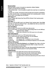
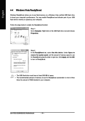
GA-P35C-DS3R/DS3/S3 Motherboard - 74 - Follow the steps below to enable the ReadyBoost function: Step 1: Go to... • The USB flash drive must have at least 256 MB of space. • The recommended amount of memory to use for ReadyBoost acceleration is one to three times the amount of RAM installed in your computer. You may ...enable ReadyBoost and allocate part of memory space to use flash memory on a Windows Vista certified USB flash drive to boost your USB flash drive's memory to Computer. Step 2: In the ReadyBoost tab, select Use this ...
GA-P35C-DS3R/DS3/S3 Motherboard - 74 - Follow the steps below to enable the ReadyBoost function: Step 1: Go to... • The USB flash drive must have at least 256 MB of space. • The recommended amount of memory to use for ReadyBoost acceleration is one to three times the amount of RAM installed in your computer. You may ...enable ReadyBoost and allocate part of memory space to use flash memory on a Windows Vista certified USB flash drive to boost your USB flash drive's memory to Computer. Step 2: In the ReadyBoost tab, select Use this ...

Manual
Page 82
...the item that you can select a hard drive in RAID BIOS Enter the RAID BIOS setup utility to enter the GIGABYTE SATA2 RAID BIOS utility. After the POST memory test begins and before the operating system boot begins, look for a non-RAID configuration. PCIE-to-SATAII/IDE RAID... Drive List block and press to execute and press . Press + to configure a RAID array. http://www.gigabyte.com.tw HDD0 : HDD1 : ST3120026AS ST3120026AS 120 GB Non-RAID 120 GB Non-RAID ODD0 : DVDROM GO-D1600B Press to enter RAID Setup Utility" (Figure 2). GA-P35C-DS3R/DS3/S3 Motherboard - 82 - English C.
...the item that you can select a hard drive in RAID BIOS Enter the RAID BIOS setup utility to enter the GIGABYTE SATA2 RAID BIOS utility. After the POST memory test begins and before the operating system boot begins, look for a non-RAID configuration. PCIE-to-SATAII/IDE RAID... Drive List block and press to execute and press . Press + to configure a RAID array. http://www.gigabyte.com.tw HDD0 : HDD1 : ST3120026AS ST3120026AS 120 GB Non-RAID 120 GB Non-RAID ODD0 : DVDROM GO-D1600B Press to enter RAID Setup Utility" (Figure 2). GA-P35C-DS3R/DS3/S3 Motherboard - 82 - English C.
Manual
Page 104
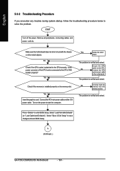
...to start the computer. No Check if the CPU cooler is verified and solved. Press to solve the problem. Yes Check if the memory is verified and solved. Yes Isolate the short circuit. English 5-3-2 Troubleshooting Procedure If you encounter any troubles during system startup, follow the...cables, and power cord etc. Make sure the motherboard does not short-circuit with the chassis or other metal objects. A (Continued...) GA-P35C-DS3R/DS3/S3 Motherboard - 104 - START Turn off the power. Is the power connector of the CPU cooler connected to the motherboard. The problem is...
...to start the computer. No Check if the CPU cooler is verified and solved. Press to solve the problem. Yes Check if the memory is verified and solved. Yes Isolate the short circuit. English 5-3-2 Troubleshooting Procedure If you encounter any troubles during system startup, follow the...cables, and power cord etc. Make sure the motherboard does not short-circuit with the chassis or other metal objects. A (Continued...) GA-P35C-DS3R/DS3/S3 Motherboard - 104 - START Turn off the power. Is the power connector of the CPU cooler connected to the motherboard. The problem is...


