Manual
Page 28
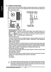
...turn off (S5). • PW (Power Switch, Red): Connects to the pin assignments below. One single short beep will be heard if no problem is detected, the BIOS may differ by issuing a beep code. When connecting your system using the power switch (refer to Chapter 2, "BIOS ...) Connects to indicate the problem. Note the positive and negative pins before connecting the cables. RESRES+ NC IDE Hard Disk Reset Active LED Switch • MSG (Message/Power/Sleep LED, Yellow): System Status LED Connects to the speaker on the chassis front panel. GA-P35C-DS3R/DS3/S3 Motherboard - 28 ...
...turn off (S5). • PW (Power Switch, Red): Connects to the pin assignments below. One single short beep will be heard if no problem is detected, the BIOS may differ by issuing a beep code. When connecting your system using the power switch (refer to Chapter 2, "BIOS ...) Connects to indicate the problem. Note the positive and negative pins before connecting the cables. RESRES+ NC IDE Hard Disk Reset Active LED Switch • MSG (Message/Power/Sleep LED, Yellow): System Status LED Connects to the speaker on the chassis front panel. GA-P35C-DS3R/DS3/S3 Motherboard - 28 ...
Manual
Page 104
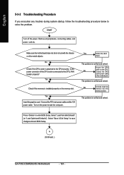
... main power cable and the 12V power cable. Yes Isolate the short circuit. No Correctly insert the memory into the memory socket. A (Continued...) GA-P35C-DS3R/DS3/S3 Motherboard - 104 - The problem is verified and solved. English 5-3-2 Troubleshooting Procedure If you encounter any troubles during system startup, follow the troubleshooting procedure below to the motherboard...
... main power cable and the 12V power cable. Yes Isolate the short circuit. No Correctly insert the memory into the memory socket. A (Continued...) GA-P35C-DS3R/DS3/S3 Motherboard - 104 - The problem is verified and solved. English 5-3-2 Troubleshooting Procedure If you encounter any troubles during system startup, follow the troubleshooting procedure below to the motherboard...


