Manual
Page 1
GA-P35-S3G LGA775 socket motherboard for Intel® CoreTM processor family/ Intel® Pentium® processor family/Intel® Celeron® processor family User's Manual Rev. 1002 12ME-P35S3G-1002R
GA-P35-S3G LGA775 socket motherboard for Intel® CoreTM processor family/ Intel® Pentium® processor family/Intel® Celeron® processor family User's Manual Rev. 1002 12ME-P35S3G-1002R
Manual
Page 2
Motherboard GA-P35-S3G Nov. 14, 2007 Motherboard GA-P35-S3G Nov. 14, 2007
Motherboard GA-P35-S3G Nov. 14, 2007 Motherboard GA-P35-S3G Nov. 14, 2007
Manual
Page 4
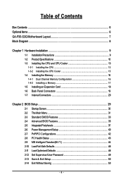
Table of Contents Box Contents ...6 OptionalItems ...6 GA-P35-S3G Motherboard Layout 7 Block Diagram ...8 Chapter 1 Hardware Installation 9 1-1 Installation Precautions 9 1-2 Product Specifications 10 1-3 Installing the CPU and CPU Cooler 13 1-3-1 Installing the CPU 13 1-3-2 Installing the ...
Table of Contents Box Contents ...6 OptionalItems ...6 GA-P35-S3G Motherboard Layout 7 Block Diagram ...8 Chapter 1 Hardware Installation 9 1-1 Installation Precautions 9 1-2 Product Specifications 10 1-3 Installing the CPU and CPU Cooler 13 1-3-1 Installing the CPU 13 1-3-2 Installing the ...
Manual
Page 6
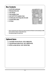
... 2.0 bracket (Part No. 12CR1-1UB030-51R) 2-port SATA power cable (Part No. 12CF1-2SERPW-01R) S/PDIF out cable (Part No. 12CR1-1SPOUT-02R) - 6 - Box Contents GA-P35-S3G motherboard Motherboard driver disk User's Manual Quick Installation Guide Intel® LGA775 CPU Installation Guide One IDE cable and one floppy disk drive cable Two...
... 2.0 bracket (Part No. 12CR1-1UB030-51R) 2-port SATA power cable (Part No. 12CF1-2SERPW-01R) S/PDIF out cable (Part No. 12CR1-1SPOUT-02R) - 6 - Box Contents GA-P35-S3G motherboard Motherboard driver disk User's Manual Quick Installation Guide Intel® LGA775 CPU Installation Guide One IDE cable and one floppy disk drive cable Two...
Manual
Page 7
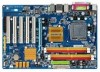
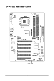
GA-P35-S3G Motherboard Layout KB_MS ATX_12V LGA775 CPU_FAN COMA LPT R_USB USB_LAN AUDIO F_AUDIO RTL8111B PCIE_1 PCIE_16 IT8718 PCI1 CODEC PCI2 CD_IN PCI3 SPDIF_O PCI4 PCI5 FDD IDE ATX GA-P35-S3G DDRII1 DDRII2 DDRII3 DDRII4 JMicron 368 PWR_FAN Intel® P35 SYS_FAN1 Intel® ICH9 SATAII0 SATAII1 SATAII4 MBIOS BATTERY SATAII5 CLR_CMOS SYS_FAN2 PWR_LED F_USB1 CI F_PANEL F_USB3 F_USB2 - 7 -
GA-P35-S3G Motherboard Layout KB_MS ATX_12V LGA775 CPU_FAN COMA LPT R_USB USB_LAN AUDIO F_AUDIO RTL8111B PCIE_1 PCIE_16 IT8718 PCI1 CODEC PCI2 CD_IN PCI3 SPDIF_O PCI4 PCI5 FDD IDE ATX GA-P35-S3G DDRII1 DDRII2 DDRII3 DDRII4 JMicron 368 PWR_FAN Intel® P35 SYS_FAN1 Intel® ICH9 SATAII0 SATAII1 SATAII4 MBIOS BATTERY SATAII5 CLR_CMOS SYS_FAN2 PWR_LED F_USB1 CI F_PANEL F_USB3 F_USB2 - 7 -

Manual
Page 8
Block Diagram PCIe CLK (100 MHz) LGA775 Processor CPU CLK+/(333/266/200 MHz) Host Interface DDR2 1066/800/667 MHz PCI Express x16 ATA-133/100/66/33 IDE Channel PCI Express Bus 1 PCI Express x1 x 1 PCIe CLK (100 MHz) PCI Bus JMicron 368 x1 x1 RTL 8111B RJ45 LAN Intel® P35 Intel® ICH9 IT8208M CODEC Dual Channel Memory MCH CLK (333/266/200 MHz) BIOS 4 SATA 3Gb/s 12 USB Ports IT8718 Floppy LPT Port COM Port PS/2 KB/Mouse MIC (Center/Subwoofer Speaker Out) Line-Out (Front Speaker Out) Line-In (Rear Speaker Out) SPDIF Out 5 PCI PCI CLK (33 MHz) - 8 -
Block Diagram PCIe CLK (100 MHz) LGA775 Processor CPU CLK+/(333/266/200 MHz) Host Interface DDR2 1066/800/667 MHz PCI Express x16 ATA-133/100/66/33 IDE Channel PCI Express Bus 1 PCI Express x1 x 1 PCIe CLK (100 MHz) PCI Bus JMicron 368 x1 x1 RTL 8111B RJ45 LAN Intel® P35 Intel® ICH9 IT8208M CODEC Dual Channel Memory MCH CLK (333/266/200 MHz) BIOS 4 SATA 3Gb/s 12 USB Ports IT8718 Floppy LPT Port COM Port PS/2 KB/Mouse MIC (Center/Subwoofer Speaker Out) Line-Out (Front Speaker Out) Line-In (Rear Speaker Out) SPDIF Out 5 PCI PCI CLK (33 MHz) - 8 -
Manual
Page 10
...Edition/Intel® Pentium® 4 processor/ Intel® Celeron® processor in the LGA 775 package (Go to GIGABYTE's website for the latest CPU support list.) Š L2 cache varies with CPU Š 1333/1066/800 MHz FSB Š...memory (Note 1) Š Dual channel memory architecture Š Support for DDR2 1066/800/667 MHz memory modules (Go to GIGABYTE's website for the latest memory support list.) Š Realtek AL662 codec Š High Definition Audio Š 2/4/5.1-channel Š...the back panel, 6 via the USB brackets connected to the internal USB headers) GA-P35-S3G Motherboard - 10 -
...Edition/Intel® Pentium® 4 processor/ Intel® Celeron® processor in the LGA 775 package (Go to GIGABYTE's website for the latest CPU support list.) Š L2 cache varies with CPU Š 1333/1066/800 MHz FSB Š...memory (Note 1) Š Dual channel memory architecture Š Support for DDR2 1066/800/667 MHz memory modules (Go to GIGABYTE's website for the latest memory support list.) Š Realtek AL662 codec Š High Definition Audio Š 2/4/5.1-channel Š...the back panel, 6 via the USB brackets connected to the internal USB headers) GA-P35-S3G Motherboard - 10 -
Manual
Page 12
GA-P35-S3G Motherboard - 12 - BIOS Unique Features Bundled Software Operating System Form Factor Š 1 x 8 Mbit flash Š Use of licensed AWARD BIOS Š PnP 1.0a, DMI 2.0, SM ...
GA-P35-S3G Motherboard - 12 - BIOS Unique Features Bundled Software Operating System Form Factor Š 1 x 8 Mbit flash Š Use of licensed AWARD BIOS Š PnP 1.0a, DMI 2.0, SM ...
Manual
Page 14
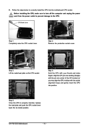
... metal load plate on the CPU socket. Step 4: Hold the CPU with the socket alignment keys) and gently insert the CPU into its locked position. GA-P35-S3G Motherboard - 14 - CPU Socket Lever Step 1: Completely raise the CPU socket lever. Align the CPU pin one marking (triangle) with the pin one corner of...
... metal load plate on the CPU socket. Step 4: Hold the CPU with the socket alignment keys) and gently insert the CPU into its locked position. GA-P35-S3G Motherboard - 14 - CPU Socket Lever Step 1: Completely raise the CPU socket lever. Align the CPU pin one marking (triangle) with the pin one corner of...
Manual
Page 16
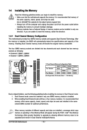
... the motherboard supports the memory. Enabling Dual Channel memory mode will appear during the POST. GA-P35-S3G Motherboard - 16 - After the memory is recommended that memory of the same capacity, brand, speed, and chips be used . (Go to GIGABYTE's website for optimum performance. The four DDR2 memory sockets are unable to prevent hardware...
... the motherboard supports the memory. Enabling Dual Channel memory mode will appear during the POST. GA-P35-S3G Motherboard - 16 - After the memory is recommended that memory of the same capacity, brand, speed, and chips be used . (Go to GIGABYTE's website for optimum performance. The four DDR2 memory sockets are unable to prevent hardware...
Manual
Page 18
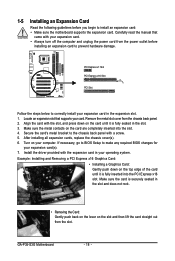
...: Gently push back on the lever on your card. Turn on the slot and then lift the card straight out from the chassis back panel. 2. GA-P35-S3G Motherboard - 18 - If necessary, go to BIOS Setup to make any required BIOS changes for your operating system.
...: Gently push back on the lever on your card. Turn on the slot and then lift the card straight out from the chassis back panel. 2. GA-P35-S3G Motherboard - 18 - If necessary, go to BIOS Setup to make any required BIOS changes for your operating system.

Manual
Page 20
... device and before connecting external devices: • First make sure the device cable has been securely attached to turn off the devices and your computer. GA-P35-S3G Motherboard - 20 -
... device and before connecting external devices: • First make sure the device cable has been securely attached to turn off the devices and your computer. GA-P35-S3G Motherboard - 20 -

Manual
Page 22
... 2 +12V 3 Sense • Be sure to connect fan cables to the fan headers to connect a floppy disk drive. The pin 1 of different color. 33 1 34 2 GA-P35-S3G Motherboard - 22 - Most fans are designed with fan speed control design. When connecting a fan cable, be installed inside the chassis. The black connector wire is...
... 2 +12V 3 Sense • Be sure to connect fan cables to the fan headers to connect a floppy disk drive. The pin 1 of different color. 33 1 34 2 GA-P35-S3G Motherboard - 22 - Most fans are designed with fan speed control design. When connecting a fan cable, be installed inside the chassis. The black connector wire is...
Manual
Page 24
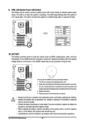
... wait for 5 seconds.) 3. Definition 1 MPD+ 2 MPD- 1 3 MPD- You may be lost. Turn off when the system is operating. Plug in accordance with local environmental regulations. GA-P35-S3G Motherboard - 24 - The LED is off your computer and unplug the power cord before replacing the battery. • Replace the battery with an incorrect model...
... wait for 5 seconds.) 3. Definition 1 MPD+ 2 MPD- 1 3 MPD- You may be lost. Turn off when the system is operating. Plug in accordance with local environmental regulations. GA-P35-S3G Motherboard - 24 - The LED is off your computer and unplug the power cord before replacing the battery. • Replace the battery with an incorrect model...
Manual
Page 26
... contact the chassis manufacturer. 13) CD_IN (CD In Connector) You may connect your optical drive to the header. 1 Pin No. Definition 1 CD-L 2 GND 3 GND 4 CD-R GA-P35-S3G Motherboard - 26 - Make sure the wire assignments of the module connector match the pin assignments of a single plug. For HD Front Panel Audio: For AC...
... contact the chassis manufacturer. 13) CD_IN (CD In Connector) You may connect your optical drive to the header. 1 Pin No. Definition 1 CD-L 2 GND 3 GND 4 CD-R GA-P35-S3G Motherboard - 26 - Make sure the wire assignments of the module connector match the pin assignments of a single plug. For HD Front Panel Audio: For AC...

Manual
Page 28
Pin No. GA-P35-S3G Motherboard - 28 - date information and BIOS configurations) and reset the CMOS values to Chapter 2, "BIOS Setup," for a few seconds. Open: Normal Short: Clear CMOS Values &#...
Pin No. GA-P35-S3G Motherboard - 28 - date information and BIOS configurations) and reset the CMOS values to Chapter 2, "BIOS Setup," for a few seconds. Open: Normal Short: Clear CMOS Values &#...
Manual
Page 30
Intel P35 BIOS for P35-S3G E8 . . . . : BIOS Setup/Q-Flash : XpressRecovery2 : Boot Menu : Qflash 11/05/2007-P35-ICH9-6A89OG0GC-00 Function Keys Function Keys: : POST Screen Press the key to accept. The system will still be used for one time ... Setup Press the key to enter BIOS Setup. : Xpress Recovery2 If you to set the first boot device without having to XpressRecovery2 during the POST. GA-P35-S3G Motherboard - 30 - Note: The setting in Boot Menu. The LOGO Screen (Default) : POST Screen : BIOS Setup/Q-Flash : XpressRecovery2 : Boot Menu: Qflash Function Keys...
Intel P35 BIOS for P35-S3G E8 . . . . : BIOS Setup/Q-Flash : XpressRecovery2 : Boot Menu : Qflash 11/05/2007-P35-ICH9-6A89OG0GC-00 Function Keys Function Keys: : POST Screen Press the key to accept. The system will still be used for one time ... Setup Press the key to enter BIOS Setup. : Xpress Recovery2 If you to set the first boot device without having to XpressRecovery2 during the POST. GA-P35-S3G Motherboard - 30 - Note: The setting in Boot Menu. The LOGO Screen (Default) : POST Screen : BIOS Setup/Q-Flash : XpressRecovery2 : Boot Menu: Qflash Function Keys...

Manual
Page 32
... you to restrict access to see information about autodetected system/CPU temperature, system voltage and fan speed, etc. „ MB Intelligent Tweaker(M.I.T.) Use this task.) GA-P35-S3G Motherboard - 32 - You can use the SPACE key) and then press to complete. ` F12 : Load CMOS from a profile created before, without the hassles of the...
... you to restrict access to see information about autodetected system/CPU temperature, system voltage and fan speed, etc. „ MB Intelligent Tweaker(M.I.T.) Use this task.) GA-P35-S3G Motherboard - 32 - You can use the SPACE key) and then press to complete. ` F12 : Load CMOS from a profile created before, without the hassles of the...

Manual
Page 34
... system. All Errors Whenever the BIOS detects a non-fatal error the system boot will stop for all other errors. Base Memory Also called conventional memory. GA-P35-S3G Motherboard - 34 - If you to determine whether the system will not stop for a floppy disk drive error but stop for all other errors. (Default) All...
... system. All Errors Whenever the BIOS detects a non-fatal error the system boot will stop for all other errors. Base Memory Also called conventional memory. GA-P35-S3G Motherboard - 34 - If you to determine whether the system will not stop for a floppy disk drive error but stop for all other errors. (Default) All...
Manual
Page 36
...) Enables or disables Intel® Execute Disable Bit function. For more information about Intel CPUs' unique features, please visit Intel's website. GA-P35-S3G Motherboard - 36 - Set this item to decrease average power consumption and heat production. (Default: Enabled) Virtualization Technology (Note) Enables or...174; Virtualization Technology. When enabled, the CPU core frequency and voltage will be reduced during system halt state to display the GIGABYTE Logo at system startup. set this feature. PCI Sets the PCI graphics card as the first display. (Default) PEG Sets...
...) Enables or disables Intel® Execute Disable Bit function. For more information about Intel CPUs' unique features, please visit Intel's website. GA-P35-S3G Motherboard - 36 - Set this item to decrease average power consumption and heat production. (Default: Enabled) Virtualization Technology (Note) Enables or...174; Virtualization Technology. When enabled, the CPU core frequency and voltage will be reduced during system halt state to display the GIGABYTE Logo at system startup. set this feature. PCI Sets the PCI graphics card as the first display. (Default) PEG Sets...
