Manual
Page 4
Table of Contents Box Contents ...6 OptionalItems ...6 GA-P35-S3G Motherboard Layout 7 Block Diagram ...8 Chapter 1 Hardware Installation 9 1-1 Installation Precautions 9 1-2 Product Specifications 10 1-3 Installing the CPU and CPU Cooler 13 1-3-1 Installing the CPU 13 1-3-2 Installing the CPU Cooler 15 1-4 Installing the Memory 16 1-4-1 Dual Channel Memory Configuration 16 1-4-2 Installing a Memory 17 1-5 Installing an Expansion Card 18 1-6 Back Panel Connectors 19...
Table of Contents Box Contents ...6 OptionalItems ...6 GA-P35-S3G Motherboard Layout 7 Block Diagram ...8 Chapter 1 Hardware Installation 9 1-1 Installation Precautions 9 1-2 Product Specifications 10 1-3 Installing the CPU and CPU Cooler 13 1-3-1 Installing the CPU 13 1-3-2 Installing the CPU Cooler 15 1-4 Installing the Memory 16 1-4-1 Dual Channel Memory Configuration 16 1-4-2 Installing a Memory 17 1-5 Installing an Expansion Card 18 1-6 Back Panel Connectors 19...
Manual
Page 6
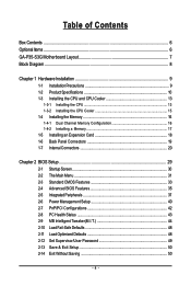
...) 2-port SATA power cable (Part No. 12CF1-2SERPW-01R) S/PDIF out cable (Part No. 12CR1-1SPOUT-02R) - 6 - Box Contents GA-P35-S3G motherboard Motherboard driver disk User's Manual Quick Installation Guide Intel® LGA775 CPU Installation Guide One IDE cable and one floppy disk drive cable Two SATA 3Gb/s cables I/O Shield • The box...
...) 2-port SATA power cable (Part No. 12CF1-2SERPW-01R) S/PDIF out cable (Part No. 12CR1-1SPOUT-02R) - 6 - Box Contents GA-P35-S3G motherboard Motherboard driver disk User's Manual Quick Installation Guide Intel® LGA775 CPU Installation Guide One IDE cable and one floppy disk drive cable Two SATA 3Gb/s cables I/O Shield • The box...

Manual
Page 8
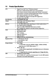
Block Diagram PCIe CLK (100 MHz) LGA775 Processor CPU CLK+/(333/266/200 MHz) Host Interface DDR2 1066/800/667 MHz PCI Express x16 ATA-133/100/66/33 IDE Channel PCI Express Bus 1 PCI Express x1 x 1 PCIe CLK (100 MHz) PCI Bus JMicron 368 x1 x1 RTL 8111B RJ45 LAN Intel® P35 Intel® ICH9 IT8208M CODEC Dual Channel Memory MCH CLK (333/266/200 MHz) BIOS 4 SATA 3Gb/s 12 USB Ports IT8718 Floppy LPT Port COM Port PS/2 KB/Mouse MIC (Center/Subwoofer Speaker Out) Line-Out (Front Speaker Out) Line-In (Rear Speaker Out) SPDIF Out 5 PCI PCI CLK (33 MHz) - 8 -
Block Diagram PCIe CLK (100 MHz) LGA775 Processor CPU CLK+/(333/266/200 MHz) Host Interface DDR2 1066/800/667 MHz PCI Express x16 ATA-133/100/66/33 IDE Channel PCI Express Bus 1 PCI Express x1 x 1 PCIe CLK (100 MHz) PCI Bus JMicron 368 x1 x1 RTL 8111B RJ45 LAN Intel® P35 Intel® ICH9 IT8208M CODEC Dual Channel Memory MCH CLK (333/266/200 MHz) BIOS 4 SATA 3Gb/s 12 USB Ports IT8718 Floppy LPT Port COM Port PS/2 KB/Mouse MIC (Center/Subwoofer Speaker Out) Line-Out (Front Speaker Out) Line-In (Rear Speaker Out) SPDIF Out 5 PCI PCI CLK (33 MHz) - 8 -

Manual
Page 9
... other hardware components. • When connecting hardware components to the internal connectors on the computer power during the installation process can become damaged as a motherboard, CPU or memory. Prior to installation, carefully read the user's manual and follow these procedures: • Prior to installation, do not allow screws to come in...
... other hardware components. • When connecting hardware components to the internal connectors on the computer power during the installation process can become damaged as a motherboard, CPU or memory. Prior to installation, carefully read the user's manual and follow these procedures: • Prior to installation, do not allow screws to come in...
Manual
Page 10
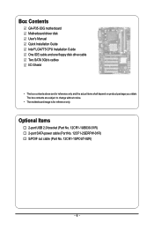
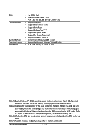
...® 4 processor/ Intel® Celeron® processor in the LGA 775 package (Go to GIGABYTE's website for the latest CPU support list.) Š L2 cache varies with CPU Š 1333/1066/800 MHz FSB Š North Bridge: Intel® P35 Express Chipset Š South Bridge: Intel® ICH9 Š 4 x 1.8V DDR2 DIMM sockets supporting...; Integrated in the South Bridge Š Up to 12 USB 2.0/1.1 ports (6 on the back panel, 6 via the USB brackets connected to the internal USB headers) GA-P35-S3G Motherboard - 10 -
...® 4 processor/ Intel® Celeron® processor in the LGA 775 package (Go to GIGABYTE's website for the latest CPU support list.) Š L2 cache varies with CPU Š 1333/1066/800 MHz FSB Š North Bridge: Intel® P35 Express Chipset Š South Bridge: Intel® ICH9 Š 4 x 1.8V DDR2 DIMM sockets supporting...; Integrated in the South Bridge Š Up to 12 USB 2.0/1.1 ports (6 on the back panel, 6 via the USB brackets connected to the internal USB headers) GA-P35-S3G Motherboard - 10 -

Manual
Page 11
...; 1 x 4-pin ATX 12V power connector Š 1 x floppy disk drive connector Š 1 x IDE connector Š 4 x SATA 3Gb/s connectors Š 1 x CPU fan header Š 2 x system fan headers Š 1 x power fan header Š 1 x front panel header Š 1 x front panel audio header Š ...) I/O Controller Š iTE IT8718 chip Hardware Monitor Š System voltage detection Š CPU/System temperature detection Š CPU/System/Power fan speed detection Š CPU overheating warning Š CPU/System/Power fan fail warning Š CPU samrt fan control (Note 3) - 11 -
...; 1 x 4-pin ATX 12V power connector Š 1 x floppy disk drive connector Š 1 x IDE connector Š 4 x SATA 3Gb/s connectors Š 1 x CPU fan header Š 2 x system fan headers Š 1 x power fan header Š 1 x front panel header Š 1 x front panel audio header Š ...) I/O Controller Š iTE IT8718 chip Hardware Monitor Š System voltage detection Š CPU/System temperature detection Š CPU/System/Power fan speed detection Š CPU overheating warning Š CPU/System/Power fan fail warning Š CPU samrt fan control (Note 3) - 11 -
Manual
Page 12
... Vista only) and configure the SATA connectors for AHCI mode. (Refer to Chapter 2, "BIOS Setup," "Integrated Peripherals," for details on enabling AHCI.) (Note 3) Whether the CPU fan speed control function is supported will depend on the CPU cooler you install. (Note 4) Available functions in Easytune may differ by motherboard model. GA-P35-S3G Motherboard - 12 -
... Vista only) and configure the SATA connectors for AHCI mode. (Refer to Chapter 2, "BIOS Setup," "Integrated Peripherals," for details on enabling AHCI.) (Note 3) Whether the CPU fan speed control function is supported will depend on the CPU cooler you install. (Note 4) Available functions in Easytune may differ by motherboard model. GA-P35-S3G Motherboard - 12 -
Manual
Page 13
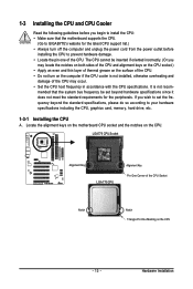
... specifications, please do so according to your hardware specifications including the CPU, graphics card, memory, hard drive, etc. 1-3-1 Installing the CPU A. Hardware Installation mended that the motherboard supports the CPU. (Go to GIGABYTE's website for the peripherals. LGA775 CPU Socket Alignment Key LGA 775 CPU Alignment Key Pin One Corner of thermal grease on the computer...
... specifications, please do so according to your hardware specifications including the CPU, graphics card, memory, hard drive, etc. 1-3-1 Installing the CPU A. Hardware Installation mended that the motherboard supports the CPU. (Go to GIGABYTE's website for the peripherals. LGA775 CPU Socket Alignment Key LGA 775 CPU Alignment Key Pin One Corner of thermal grease on the computer...
Manual
Page 14
... position. Step 2: Remove the protective socket cover. Step 5: Once the CPU is properly inserted, replace the load plate and push the CPU socket lever back into the motherboard CPU socket. B. Step 3: Lift the metal load plate on the CPU socket. GA-P35-S3G Motherboard - 14 - Follow the steps below to the CPU. CPU Socket Lever Step 1: Completely raise the...
... position. Step 2: Remove the protective socket cover. Step 5: Once the CPU is properly inserted, replace the load plate and push the CPU socket lever back into the motherboard CPU socket. B. Step 3: Lift the metal load plate on the CPU socket. GA-P35-S3G Motherboard - 14 - Follow the steps below to the CPU. CPU Socket Lever Step 1: Completely raise the...

Manual
Page 15
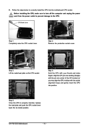
... push pins through the pin holes on the motherboard. Hardware Installation Check that the Male and Female push pins are joined closely. (Refer to your CPU cooler installation manual for instructions on installing the cooler.) Step 5: After the installation, check the back of arrow is to remove the cooler, on the... contrary, is inserted as the example cooler.) Step 1: Apply an even and thin layer of thermal grease on the surface of the CPU cooler to the CPU. Direction of the Arrow Sign on the Male Push Pin Male Push Pin The Top of Female Push Pin Female Push Pin Step 2: Before...
... push pins through the pin holes on the motherboard. Hardware Installation Check that the Male and Female push pins are joined closely. (Refer to your CPU cooler installation manual for instructions on installing the cooler.) Step 5: After the installation, check the back of arrow is to remove the cooler, on the... contrary, is inserted as the example cooler.) Step 1: Apply an even and thin layer of thermal grease on the surface of the CPU cooler to the CPU. Direction of the Arrow Sign on the Male Push Pin Male Push Pin The Top of Female Push Pin Female Push Pin Step 2: Before...

Manual
Page 21
... 24 Definition 3.3V -12V GND PS_ON(soft On/Off) GND GND GND -5V +5V +5V +5V GND - 21 - Connect the power supply cable to the CPU. If the 12V power connector is not connected, the computer will not start. • To meet expansion requirements, it is recommended that a power supply that...
... 24 Definition 3.3V -12V GND PS_ON(soft On/Off) GND GND GND -5V +5V +5V +5V GND - 21 - Connect the power supply cable to the CPU. If the 12V power connector is not connected, the computer will not start. • To meet expansion requirements, it is recommended that a power supply that...

Manual
Page 22
... FDD (Floppy Disk Drive Connector) This connector is the ground wire. 3/4/5) CPU_FAN/SYS_FAN1/SYS_FAN2/PWR_FAN (Fan Headers) The motherboard has a 4-pin CPU fan header (CPU_FAN), a 3-pin (SYS_FAN1) and a 4-pin (SYS_FAN2) system fan headers, and a 3-pin power fan header (PWR_FAN)....damage to prevent your CPU and system from overheating. Definition 1 GND 1 2 +12V CPU_FAN 3 Sense 4 Speed Control 1 SYS_FAN2 SYS_FAN2: Pin No. 1 2 3 4 Definition GND Speed Control Sense +5V SYS_FAN1/PWR_FAN: 1 Pin No. The pin 1 of different color. 33 1 34 2 GA-P35-S3G Motherboard - 22 ...
... FDD (Floppy Disk Drive Connector) This connector is the ground wire. 3/4/5) CPU_FAN/SYS_FAN1/SYS_FAN2/PWR_FAN (Fan Headers) The motherboard has a 4-pin CPU fan header (CPU_FAN), a 3-pin (SYS_FAN1) and a 4-pin (SYS_FAN2) system fan headers, and a 3-pin power fan header (PWR_FAN)....damage to prevent your CPU and system from overheating. Definition 1 GND 1 2 +12V CPU_FAN 3 Sense 4 Speed Control 1 SYS_FAN2 SYS_FAN2: Pin No. 1 2 3 4 Definition GND Speed Control Sense +5V SYS_FAN1/PWR_FAN: 1 Pin No. The pin 1 of different color. 33 1 34 2 GA-P35-S3G Motherboard - 22 ...

Manual
Page 32
...view the BIOS settings but not to make changes in effect. First enter the profile name (to erase the default profile name, use this task.) GA-P35-S3G Motherboard - 32 - Pressing to the system and BIOS Setup. It allows you to save the current BIOS settings to complete. ` F12 : Load...Use this menu to configure the system's PCI & PnP resources. „ PC Health Status Use this menu to see information about autodetected system/CPU temperature, system voltage and fan speed, etc. „ MB Intelligent Tweaker(M.I.T.) Use this menu to configure the clock, frequency and voltages of ...
...view the BIOS settings but not to make changes in effect. First enter the profile name (to erase the default profile name, use this task.) GA-P35-S3G Motherboard - 32 - Pressing to the system and BIOS Setup. It allows you to save the current BIOS settings to complete. ` F12 : Load...Use this menu to configure the system's PCI & PnP resources. „ PC Health Status Use this menu to see information about autodetected system/CPU temperature, system voltage and fan speed, etc. „ MB Intelligent Tweaker(M.I.T.) Use this menu to configure the clock, frequency and voltages of ...

Manual
Page 35
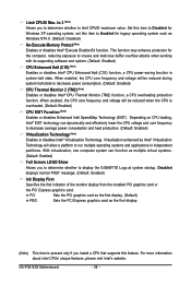
...plus key (or ) or the minus key (or ) to accept. to 3 (Note) No-Execute Memory Protect (Note) CPU Enhanced Halt (C1E) (Note) CPU Thermal Monitor 2(TM2) (Note) CPU EIST Function (Note) Virtualization Technology (Note) Full Screen LOGO Show Init Display First [Press Enter] [Floppy] [Hard Disk] ...entering the BIOS Setup program. (Default) System A password is required every time the system boots, or only when you install a CPU that supports this feature. This feature allows your hard drive. Capability Enables or disables the S.M.A.R.T. (Self Monitoring and Reporting Technology) ...
...plus key (or ) or the minus key (or ) to accept. to 3 (Note) No-Execute Memory Protect (Note) CPU Enhanced Halt (C1E) (Note) CPU Thermal Monitor 2(TM2) (Note) CPU EIST Function (Note) Virtualization Technology (Note) Full Screen LOGO Show Init Display First [Press Enter] [Floppy] [Hard Disk] ...entering the BIOS Setup program. (Default) System A password is required every time the system boots, or only when you install a CPU that supports this feature. This feature allows your hard drive. Capability Enables or disables the S.M.A.R.T. (Self Monitoring and Reporting Technology) ...
Manual
Page 36
... a platform to limit CPUID maximum value. For more information about Intel CPUs' unique features, please visit Intel's website. to 3 (Note) Allows you install a CPU that supports this item to display the GIGABYTE Logo at system startup. Set this feature. GA-P35-S3G Motherboard - 36 - With virtualization, one computer system can dynamically and effectively lower the...
... a platform to limit CPUID maximum value. For more information about Intel CPUs' unique features, please visit Intel's website. to 3 (Note) Allows you install a CPU that supports this item to display the GIGABYTE Logo at system startup. Set this feature. GA-P35-S3G Motherboard - 36 - With virtualization, one computer system can dynamically and effectively lower the...

Manual
Page 43
...speed. (Default: Enabled) - 43 - If the system chassis cover is not connected or fails. Current CPU/SYSTEM/POWER FAN Speed (RPM) Displays current CPU/system/power fan speed. You can adjust the fan speed with EasyTune based on system requirements. To clear...function. Current Voltage(V) Vcore/DDR18V/+3.3V/+12V Displays the current system voltages. Current System/CPU Temperature Displays current System/CPU temperature. CPU Warning Temperature Sets the warning threshold for CPU temperature. When CPU temperature exceeds the threshold, BIOS will show "No" at next boot. (Default: ...
...speed. (Default: Enabled) - 43 - If the system chassis cover is not connected or fails. Current CPU/SYSTEM/POWER FAN Speed (RPM) Displays current CPU/system/power fan speed. You can adjust the fan speed with EasyTune based on system requirements. To clear...function. Current Voltage(V) Vcore/DDR18V/+3.3V/+12V Displays the current system voltages. Current System/CPU Temperature Displays current System/CPU temperature. CPU Warning Temperature Sets the warning threshold for CPU temperature. When CPU temperature exceeds the threshold, BIOS will show "No" at next boot. (Default: ...
Manual
Page 44
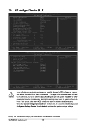
If this feature. GA-P35-S3G Motherboard - 44 - 2-9 MB Intelligent Tweaker(M.I.T.) CMOS Setup Utility-Copyright (C) 1984-2007 Award Software MB Intelligent Tweaker(M.I.T.) Robust Graphics Booster CPU Clock Ratio (Note) CPU Frequency CPU Host Clock Control x CPU Host Frequency (Mhz) PCI Express ...x Static tRead Phase Adjust ******** System Voltage Optimized System Voltage Control DDR2 OverVoltage Control FSB OverVoltage Control (G)MCH OverVoltage Control CPU Voltage Control Normal CPU Vcore 28 2 4 0 ******** 0 Auto Auto Auto [Manual] [Normal] [Normal] [Normal] [Normal] 1.30000V...
If this feature. GA-P35-S3G Motherboard - 44 - 2-9 MB Intelligent Tweaker(M.I.T.) CMOS Setup Utility-Copyright (C) 1984-2007 Award Software MB Intelligent Tweaker(M.I.T.) Robust Graphics Booster CPU Clock Ratio (Note) CPU Frequency CPU Host Clock Control x CPU Host Frequency (Mhz) PCI Express ...x Static tRead Phase Adjust ******** System Voltage Optimized System Voltage Control DDR2 OverVoltage Control FSB OverVoltage Control (G)MCH OverVoltage Control CPU Voltage Control Normal CPU Vcore 28 2 4 0 ******** 0 Auto Auto Auto [Manual] [Normal] [Normal] [Normal] [Normal] 1.30000V...

Manual
Page 45
...Memory Multiplier Allows you to 150 MHz. Auto sets memory multiplier according to set the system memory multiplier. For a 1333 MHz FSB CPU, set this item to be configurable. Options are dependent on system configurations. Important It is the normal operating frequency of the memory ... used; BIOS Setup Options are : Auto (default), Manual. (Note) This item appears only if you to enhance the performance of CPU host clock. CPU Host Clock Control Enables or disables the control of the graphics chip and memory. Options are : Auto (default), Fast, Turbo. Turbo...
...Memory Multiplier Allows you to 150 MHz. Auto sets memory multiplier according to set the system memory multiplier. For a 1333 MHz FSB CPU, set this item to be configurable. Options are dependent on system configurations. Important It is the normal operating frequency of the memory ... used; BIOS Setup Options are : Auto (default), Manual. (Note) This item appears only if you to enhance the performance of CPU host clock. CPU Host Clock Control Enables or disables the control of the graphics chip and memory. Options are : Auto (default), Fast, Turbo. Turbo...

Manual
Page 47
... to 0.3V at 0.1V increment. BIOS Setup Normal sets the CPU voltage as required. (Default) Increases North Bridge voltage by 0.1V to your CPU or reduce the useful life of your CPU. - 47 - Normal CPU Vcore Displays the normal operating voltage of the CPU. (G)MCH OverVoltage Control Allows you to set the North Bridge voltage...
... to 0.3V at 0.1V increment. BIOS Setup Normal sets the CPU voltage as required. (Default) Increases North Bridge voltage by 0.1V to your CPU or reduce the useful life of your CPU. - 47 - Normal CPU Vcore Displays the normal operating voltage of the CPU. (G)MCH OverVoltage Control Allows you to set the North Bridge voltage...

Manual
Page 65
...setting page Confirmation/execution button Toggles among Easy Mode, Advanced Mode, and Graphics Mode Displays the CPU frequency Shows the supported function(s) Go to GIGABYTE website to update EasyTune 5 Pro Opens EasyTune 5 Pro help file Quits or minimizes the EasyTune... 5 Pro interface Performance Enhancement Incorrectly doing overclock/overvoltage may provide optimizations for CPU and memory, enhancing the performance of these components. - 65 -...
...setting page Confirmation/execution button Toggles among Easy Mode, Advanced Mode, and Graphics Mode Displays the CPU frequency Shows the supported function(s) Go to GIGABYTE website to update EasyTune 5 Pro Opens EasyTune 5 Pro help file Quits or minimizes the EasyTune... 5 Pro interface Performance Enhancement Incorrectly doing overclock/overvoltage may provide optimizations for CPU and memory, enhancing the performance of these components. - 65 -...


