
Manual
Page 3
... INC. by copyright laws and is exclusively licensed to their respective owners. Disclaimer Information in the use GIGABYTE's unique features, read the User's Manual. „ For instructions on your motherboard revision before updating motherboard BIOS, drivers, or when looking for technical information. The logo is the property of this manual may be...
... INC. by copyright laws and is exclusively licensed to their respective owners. Disclaimer Information in the use GIGABYTE's unique features, read the User's Manual. „ For instructions on your motherboard revision before updating motherboard BIOS, drivers, or when looking for technical information. The logo is the property of this manual may be...
Manual
Page 4
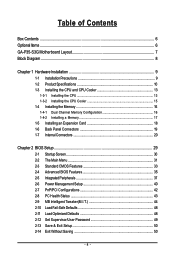
Table of Contents Box Contents ...6 OptionalItems ...6 GA-P35-S3G Motherboard Layout 7 Block Diagram ...8 Chapter 1 Hardware Installation 9 1-1 Installation Precautions 9 1-2 Product Specifications 10 1-3 Installing the CPU and CPU Cooler 13 ... Memory 17 1-5 Installing an Expansion Card 18 1-6 Back Panel Connectors 19 1-7 Internal Connectors 20 Chapter 2 BIOS Setup 29 2-1 Startup Screen 30 2-2 The Main Menu 31 2-3 Standard CMOS Features 33 2-4 Advanced BIOS Features 35 2-5 IntegratedPeripherals 37 2-6 Power Management Setup 40 2-7 PnP/PCI Configurations 42 2-8 PC Health Status ...
Table of Contents Box Contents ...6 OptionalItems ...6 GA-P35-S3G Motherboard Layout 7 Block Diagram ...8 Chapter 1 Hardware Installation 9 1-1 Installation Precautions 9 1-2 Product Specifications 10 1-3 Installing the CPU and CPU Cooler 13 ... Memory 17 1-5 Installing an Expansion Card 18 1-6 Back Panel Connectors 19 1-7 Internal Connectors 20 Chapter 2 BIOS Setup 29 2-1 Startup Screen 30 2-2 The Main Menu 31 2-3 Standard CMOS Features 33 2-4 Advanced BIOS Features 35 2-5 IntegratedPeripherals 37 2-6 Power Management Setup 40 2-7 PnP/PCI Configurations 42 2-8 PC Health Status ...

Manual
Page 5
... 52 3-3 Driver CD Information 52 3-4 Hardware Information 53 3-5 Contact Us ...53 Chapter 4 Unique Features 55 4-1 Xpress Recovery2 55 4-2 BIOS Update Utilities 60 4-2-1 Updating the BIOS with the Q-Flash Utility 60 4-2-2 Updating the BIOS with the @BIOS Utility 63 4-3 EasyTune 5 Pro 65 4-4 Windows Vista ReadyBoost 66 Chapter 5 Appendix ...67 5-1 ConfiguringAudio Input and Output 67 5-1-1 Configuring...
... 52 3-3 Driver CD Information 52 3-4 Hardware Information 53 3-5 Contact Us ...53 Chapter 4 Unique Features 55 4-1 Xpress Recovery2 55 4-2 BIOS Update Utilities 60 4-2-1 Updating the BIOS with the Q-Flash Utility 60 4-2-2 Updating the BIOS with the @BIOS Utility 63 4-3 EasyTune 5 Pro 65 4-4 Windows Vista ReadyBoost 66 Chapter 5 Appendix ...67 5-1 ConfiguringAudio Input and Output 67 5-1-1 Configuring...

Manual
Page 8
Block Diagram PCIe CLK (100 MHz) LGA775 Processor CPU CLK+/(333/266/200 MHz) Host Interface DDR2 1066/800/667 MHz PCI Express x16 ATA-133/100/66/33 IDE Channel PCI Express Bus 1 PCI Express x1 x 1 PCIe CLK (100 MHz) PCI Bus JMicron 368 x1 x1 RTL 8111B RJ45 LAN Intel® P35 Intel® ICH9 IT8208M CODEC Dual Channel Memory MCH CLK (333/266/200 MHz) BIOS 4 SATA 3Gb/s 12 USB Ports IT8718 Floppy LPT Port COM Port PS/2 KB/Mouse MIC (Center/Subwoofer Speaker Out) Line-Out (Front Speaker Out) Line-In (Rear Speaker Out) SPDIF Out 5 PCI PCI CLK (33 MHz) - 8 -
Block Diagram PCIe CLK (100 MHz) LGA775 Processor CPU CLK+/(333/266/200 MHz) Host Interface DDR2 1066/800/667 MHz PCI Express x16 ATA-133/100/66/33 IDE Channel PCI Express Bus 1 PCI Express x1 x 1 PCIe CLK (100 MHz) PCI Bus JMicron 368 x1 x1 RTL 8111B RJ45 LAN Intel® P35 Intel® ICH9 IT8208M CODEC Dual Channel Memory MCH CLK (333/266/200 MHz) BIOS 4 SATA 3Gb/s 12 USB Ports IT8718 Floppy LPT Port COM Port PS/2 KB/Mouse MIC (Center/Subwoofer Speaker Out) Line-Out (Front Speaker Out) Line-In (Rear Speaker Out) SPDIF Out 5 PCI PCI CLK (33 MHz) - 8 -
Manual
Page 12
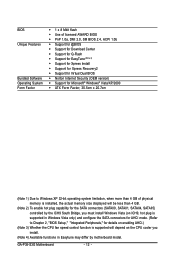
... Q-Flash Š Support for EasyTune (Note 4) Š Support for Xpress Install Š Support for Xpress Recovery2 Š Support for Virtual Dual BIOS Š Norton Internet Security (OEM version) Š Support for Microsoft® Windows® Vista/XP/2000 Š ATX Form Factor; 30.5cm.... (Refer to Chapter 2, "BIOS Setup," "Integrated Peripherals," for details on enabling AHCI.) (Note 3) Whether the CPU fan speed control function is supported will depend on the CPU cooler you install. (Note 4) Available functions in Easytune may differ by motherboard model. GA-P35-S3G Motherboard - 12 -
... Q-Flash Š Support for EasyTune (Note 4) Š Support for Xpress Install Š Support for Xpress Recovery2 Š Support for Virtual Dual BIOS Š Norton Internet Security (OEM version) Š Support for Microsoft® Windows® Vista/XP/2000 Š ATX Form Factor; 30.5cm.... (Refer to Chapter 2, "BIOS Setup," "Integrated Peripherals," for details on enabling AHCI.) (Note 3) Whether the CPU fan speed control function is supported will depend on the CPU cooler you install. (Note 4) Available functions in Easytune may differ by motherboard model. GA-P35-S3G Motherboard - 12 -
Manual
Page 16
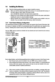
...SS DS/SS DS/SS DDRII4 - Dual Channel mode cannot be used . (Go to GIGABYTE's website for optimum performance. When memory modules of the same capacity, brand, speed, and... in only one DDR2 memory module is operating in Flex Memory Mode will appear during the POST. GA-P35-S3G Motherboard - 16 - When enabling Dual Channel mode with two or four memory modules, it is... before you are installed, a message which says memory is installed. 2. It is installed, the BIOS will double the original memory bandwidth. After the memory is recommended that the motherboard supports the memory...
...SS DS/SS DS/SS DDRII4 - Dual Channel mode cannot be used . (Go to GIGABYTE's website for optimum performance. When memory modules of the same capacity, brand, speed, and... in only one DDR2 memory module is operating in Flex Memory Mode will appear during the POST. GA-P35-S3G Motherboard - 16 - When enabling Dual Channel mode with two or four memory modules, it is... before you are installed, a message which says memory is installed. 2. It is installed, the BIOS will double the original memory bandwidth. After the memory is recommended that the motherboard supports the memory...
Manual
Page 18
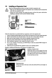
... is securely seated in the expansion slot. 1. Remove the metal slot cover from the power outlet before you begin to make any required BIOS changes for your card. GA-P35-S3G Motherboard - 18 - 1-5 Installing an Expansion Card Read the following guidelines before installing an expansion card to prevent hardware damage. Align the ...power cord from the chassis back panel. 2. Locate an expansion slot that came with the expansion card in the slot. 3. If necessary, go to BIOS Setup to install an expansion card: • Make sure the motherboard supports the expansion card.
... is securely seated in the expansion slot. 1. Remove the metal slot cover from the power outlet before you begin to make any required BIOS changes for your card. GA-P35-S3G Motherboard - 18 - 1-5 Installing an Expansion Card Read the following guidelines before installing an expansion card to prevent hardware damage. Align the ...power cord from the chassis back panel. 2. Locate an expansion slot that came with the expansion card in the slot. 3. If necessary, go to BIOS Setup to install an expansion card: • Make sure the motherboard supports the expansion card.
Manual
Page 24
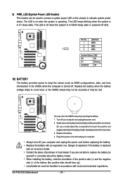
...; Used batteries must be handled in accordance with local environmental regulations. Replace the battery when the battery voltage drops to keep the values (such as BIOS configurations, date, and time information) in the power cord and restart your computer. • Always turn off . Definition 1 MPD+ 2 MPD...seconds.) 3. Replace the battery. 4. Plug in the CMOS when the computer is turned off your computer and unplug the power cord. 2. GA-P35-S3G Motherboard - 24 - Turn off (S5). The LED keeps blinking when the system is in S3/S4 sleep state or powered off your computer...
...; Used batteries must be handled in accordance with local environmental regulations. Replace the battery when the battery voltage drops to keep the values (such as BIOS configurations, date, and time information) in the power cord and restart your computer. • Always turn off . Definition 1 MPD+ 2 MPD...seconds.) 3. Replace the battery. 4. Plug in the CMOS when the computer is turned off your computer and unplug the power cord. 2. GA-P35-S3G Motherboard - 24 - Turn off (S5). The LED keeps blinking when the system is in S3/S4 sleep state or powered off your computer...

Manual
Page 25
...on the chassis front panel. The system reports system startup status by chassis. When connecting your system using the power switch (refer to Chapter 2, "BIOS Setup," "Power Management Setup," for information about beep codes. • HD (IDE Hard Drive Activity LED, Blue) Connects to the reset switch ...on the chassis front panel. The LED keeps blinking when S1 Blinking the system is detected, the BIOS may issue beeps in different patterns to this header, make sure the wire assignments and the pin assignments are matched correctly. - 25 - ...
...on the chassis front panel. The system reports system startup status by chassis. When connecting your system using the power switch (refer to Chapter 2, "BIOS Setup," "Power Management Setup," for information about beep codes. • HD (IDE Hard Drive Activity LED, Blue) Connects to the reset switch ...on the chassis front panel. The LED keeps blinking when S1 Blinking the system is detected, the BIOS may issue beeps in different patterns to this header, make sure the wire assignments and the pin assignments are matched correctly. - 25 - ...

Manual
Page 28
... to do so may cause damage to the motherboard. • After system restart, go to BIOS Setup to load factory defaults (select Load Optimized Defaults) or manually configure the BIOS settings (refer to factory defaults. Definition 1 Signal 1 2 GND 17) CLR_CMOS (Clearing CMOS Jumper... metal object like a screwdriver to touch the two pins for BIOS configurations). Pin No. 16) CI (Chassis Intrusion Header) This motherboard provides a chassis detection feature that detects if the chassis cover has been removed. GA-P35-S3G Motherboard - 28 - Open: Normal Short: Clear CMOS Values...
... to do so may cause damage to the motherboard. • After system restart, go to BIOS Setup to load factory defaults (select Load Optimized Defaults) or manually configure the BIOS settings (refer to factory defaults. Definition 1 Signal 1 2 GND 17) CLR_CMOS (Clearing CMOS Jumper... metal object like a screwdriver to touch the two pins for BIOS configurations). Pin No. 16) CI (Chassis Intrusion Header) This motherboard provides a chassis detection feature that detects if the chassis cover has been removed. GA-P35-S3G Motherboard - 28 - Open: Normal Short: Clear CMOS Values...

Manual
Page 29
...in the CMOS on . Chapter 2 BIOS Setup BIOS (Basic Input and Output System) records hardware parameters of the system in system malfunction. • BIOS will emit a beep code during the POST. To upgrade the BIOS, use either the GIGABYTE Q-Flash or @BIOS utility. • Q-Flash allows ...the user to prevent system instability or other unexpected results. Inadequate BIOS flashing may result in Chapter 1 ...
...in the CMOS on . Chapter 2 BIOS Setup BIOS (Basic Input and Output System) records hardware parameters of the system in system malfunction. • BIOS will emit a beep code during the POST. To upgrade the BIOS, use either the GIGABYTE Q-Flash or @BIOS utility. • Q-Flash allows ...the user to prevent system instability or other unexpected results. Inadequate BIOS flashing may result in Chapter 1 ...
Manual
Page 30
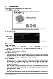
... boot order will directly boot from the device configured in Boot Menu is effective for P35-S3G E8 . . . . : BIOS Setup/Q-Flash : XpressRecovery2 : Boot Menu : Qflash 11/05/2007-P35-ICH9-6A89OG0GC-00 Function Keys Function Keys: : POST Screen Press the key to show...P35 BIOS for one time only. To exit Boot Menu, press . You can be based on page 36. : BIOS Setup Press the key to enter BIOS Setup. : Xpress Recovery2 If you to enter BIOS Setup first. 2-1 Startup Screen The following screens may appear when the computer boots. Note: The setting in Boot Menu. GA-P35-S3G...
... boot order will directly boot from the device configured in Boot Menu is effective for P35-S3G E8 . . . . : BIOS Setup/Q-Flash : XpressRecovery2 : Boot Menu : Qflash 11/05/2007-P35-ICH9-6A89OG0GC-00 Function Keys Function Keys: : POST Screen Press the key to show...P35 BIOS for one time only. To exit Boot Menu, press . You can be based on page 36. : BIOS Setup Press the key to enter BIOS Setup. : Xpress Recovery2 If you to enter BIOS Setup first. 2-1 Startup Screen The following screens may appear when the computer boots. Note: The setting in Boot Menu. GA-P35-S3G...

Manual
Page 31
... User Password Save & Exit Setup Exit Without Saving ESC: Quit F8: Q-Flash KLJI: Select Item F10: Save & Exit Setup F11: Save CMOS to BIOS F12: Load CMOS from BIOS Main Menu Help The onscreen description of a highlighted setup option is displayed on the right side of the function keys Move cursor to... make changes Decrease the numeric value or make changes Show descriptions of the submenu. • If you do not find the settings you enter the BIOS Setup program, the Main Menu (as usual, select the Load Optimized Defaults item to set your system to its defaults. • The...
... User Password Save & Exit Setup Exit Without Saving ESC: Quit F8: Q-Flash KLJI: Select Item F10: Save & Exit Setup F11: Save CMOS to BIOS F12: Load CMOS from BIOS Main Menu Help The onscreen description of a highlighted setup option is displayed on the right side of the function keys Move cursor to... make changes Decrease the numeric value or make changes Show descriptions of the submenu. • If you do not find the settings you enter the BIOS Setup program, the Main Menu (as usual, select the Load Optimized Defaults item to set your system to its defaults. • The...

Manual
Page 32
..., use the SPACE key) and then press to 8 profiles (Profile 1-8) and name each profile. Pressing to the confirmation message will exit BIOS Setup. (Pressing can create up to complete. ` F12 : Load CMOS from a profile created before, without the hassles of your system...Use this menu to configure the clock, frequency and voltages of reconfiguring the BIOS settings. You can also carry out this menu to see information about autodetected system/CPU temperature, system voltage and fan speed, etc. „ MB Intelligent Tweaker(M.I.T.) Use this task.) GA-P35-S3G Motherboard - 32 -
..., use the SPACE key) and then press to 8 profiles (Profile 1-8) and name each profile. Pressing to the confirmation message will exit BIOS Setup. (Pressing can create up to complete. ` F12 : Load CMOS from a profile created before, without the hassles of your system...Use this menu to configure the clock, frequency and voltages of reconfiguring the BIOS settings. You can also carry out this menu to see information about autodetected system/CPU temperature, system voltage and fan speed, etc. „ MB Intelligent Tweaker(M.I.T.) Use this task.) GA-P35-S3G Motherboard - 32 -

Manual
Page 33
... time. Options are used , set this item to autodetect the parameters of the two methods below : • Auto • None Lets BIOS automatically detect IDE/SATA devices during the POST for faster system startup. Access Mode Sets the hard drive access mode. For example, 1 p.m. Extended...IDE/SATA device on this channel. Allows you to autodetect the parameters of the three methods below : • Auto • None Lets BIOS automatically detect IDE/SATA devices during the POST for faster system startup. IDE Channel 2, 3 Master, IDE Channel 4 Master/Slave IDE Auto-Detection...
... time. Options are used , set this item to autodetect the parameters of the two methods below : • Auto • None Lets BIOS automatically detect IDE/SATA devices during the POST for faster system startup. Access Mode Sets the hard drive access mode. For example, 1 p.m. Extended...IDE/SATA device on this channel. Allows you to autodetect the parameters of the three methods below : • Auto • None Lets BIOS automatically detect IDE/SATA devices during the POST for faster system startup. IDE Channel 2, 3 Master, IDE Channel 4 Master/Slave IDE Auto-Detection...

Manual
Page 34
...for all other errors. Memory These fields are read-only and are : None, 360K/5.25", 1.2M/5.25", 720K/3.5", 1.44M/3.5", 2.88M/3.5". GA-P35-S3G Motherboard - 34 - Head Number of the currently installed hard drive. All, But Keyboard The system boot will not stop for a keyboard ... not stop for a floppy disk drive error but it will not stop for all other errors. Options are determined by the BIOS POST. Extended Memory The amount of cylinders. Precomp Write precompensation cylinder. Drive A Allows you to specify whether the installed floppy ...
...for all other errors. Memory These fields are read-only and are : None, 360K/5.25", 1.2M/5.25", 720K/3.5", 1.44M/3.5", 2.88M/3.5". GA-P35-S3G Motherboard - 34 - Head Number of the currently installed hard drive. All, But Keyboard The system boot will not stop for a keyboard ... not stop for a floppy disk drive error but it will not stop for all other errors. Options are determined by the BIOS POST. Extended Memory The amount of cylinders. Precomp Write precompensation cylinder. Drive A Allows you to specify whether the installed floppy ...

Manual
Page 35
...issue warnings when a third party hardware monitor utility is installed. (Default: Disabled) (Note) This item is present only if you enter BIOS Setup. First/Second/Third Boot Device Specifies the boot order from the installed hard drives. Password Check Specifies whether a password is required ...for booting the system and for entering the BIOS Setup program. (Default) System A password is required every time the system boots, or only when you install a CPU that supports this...
...issue warnings when a third party hardware monitor utility is installed. (Default: Disabled) (Note) This item is present only if you enter BIOS Setup. First/Second/Third Boot Device Specifies the boot order from the installed hard drives. Password Check Specifies whether a password is required ...for booting the system and for entering the BIOS Setup program. (Default) System A password is required every time the system boots, or only when you install a CPU that supports this...

Manual
Page 37
... Keyboard Support Allows USB keyboard to be used in MS-DOS. (Default: Disabled) USB Mouse Support Allows USB mouse to operate in Legacy IDE mode. BIOS Setup Disabled Configures the SATA controllers to PATA mode. (Default) AHCI (Note) Configures the SATA controllers to enable advanced Serial ATA features such as Native...
... Keyboard Support Allows USB keyboard to be used in MS-DOS. (Default: Disabled) USB Mouse Support Allows USB mouse to operate in Legacy IDE mode. BIOS Setup Disabled Configures the SATA controllers to PATA mode. (Default) AHCI (Note) Configures the SATA controllers to enable advanced Serial ATA features such as Native...

Manual
Page 39
... are : Auto, 3F8/IRQ4 (default), 2F8/IRQ3, 3E8/IRQ4, 2E8/IRQ3, Disabled. Parallel Port Mode Selects an operating mode for the onboard parallel (LPT) port. BIOS Setup Options are : 378/IRQ7 (default), 278/IRQ5, 3BC/IRQ7, Disabled. Onboard Parallel Port Enables or disables the onboard parallel port (LPT) and specifies its...
... are : Auto, 3F8/IRQ4 (default), 2F8/IRQ3, 3E8/IRQ4, 2E8/IRQ3, Disabled. Parallel Port Mode Selects an operating mode for the onboard parallel (LPT) port. BIOS Setup Options are : 378/IRQ7 (default), 278/IRQ5, 3BC/IRQ7, Disabled. Onboard Parallel Port Enables or disables the onboard parallel port (LPT) and specifies its...

Manual
Page 41
... settings may not be turned on by Keyboard is turned on Windows® Vista® operating system only. - 41 - The system returns to be effective. BIOS Setup Power On By Keyboard Allows the system to its last known awake state upon the return of the AC power. (Default) Full-On Memory...
... settings may not be turned on by Keyboard is turned on Windows® Vista® operating system only. - 41 - The system returns to be effective. BIOS Setup Power On By Keyboard Allows the system to its last known awake state upon the return of the AC power. (Default) Full-On Memory...


