Manual
Page 1
GA-P35-S3G LGA775 socket motherboard for Intel® CoreTM processor family/ Intel® Pentium® processor family/Intel® Celeron® processor family User's Manual Rev. 1002 12ME-P35S3G-1002R
GA-P35-S3G LGA775 socket motherboard for Intel® CoreTM processor family/ Intel® Pentium® processor family/Intel® Celeron® processor family User's Manual Rev. 1002 12ME-P35S3G-1002R
Manual
Page 2
Motherboard GA-P35-S3G Nov. 14, 2007 Motherboard GA-P35-S3G Nov. 14, 2007
Motherboard GA-P35-S3G Nov. 14, 2007 Motherboard GA-P35-S3G Nov. 14, 2007
Manual
Page 4
Table of Contents Box Contents ...6 OptionalItems ...6 GA-P35-S3G Motherboard Layout 7 Block Diagram ...8 Chapter 1 Hardware Installation 9 1-1 Installation Precautions 9 1-2 Product Specifications 10 1-3 Installing the CPU and CPU Cooler 13 1-3-1 Installing the CPU 13 1-3-2 Installing the ...
Table of Contents Box Contents ...6 OptionalItems ...6 GA-P35-S3G Motherboard Layout 7 Block Diagram ...8 Chapter 1 Hardware Installation 9 1-1 Installation Precautions 9 1-2 Product Specifications 10 1-3 Installing the CPU and CPU Cooler 13 1-3-1 Installing the CPU 13 1-3-2 Installing the ...
Manual
Page 6
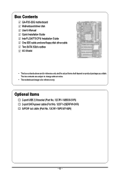
Box Contents GA-P35-S3G motherboard Motherboard driver disk User's Manual Quick Installation Guide Intel® LGA775 CPU Installation Guide One IDE cable and one floppy disk drive cable Two ...
Box Contents GA-P35-S3G motherboard Motherboard driver disk User's Manual Quick Installation Guide Intel® LGA775 CPU Installation Guide One IDE cable and one floppy disk drive cable Two ...
Manual
Page 7
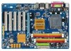
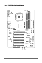
GA-P35-S3G Motherboard Layout KB_MS ATX_12V LGA775 CPU_FAN COMA LPT R_USB USB_LAN AUDIO F_AUDIO RTL8111B PCIE_1 PCIE_16 IT8718 PCI1 CODEC PCI2 CD_IN PCI3 SPDIF_O PCI4 PCI5 FDD IDE ATX GA-P35-S3G DDRII1 DDRII2 DDRII3 DDRII4 JMicron 368 PWR_FAN Intel® P35 SYS_FAN1 Intel® ICH9 SATAII0 SATAII1 SATAII4 MBIOS BATTERY SATAII5 CLR_CMOS SYS_FAN2 PWR_LED F_USB1 CI F_PANEL F_USB3 F_USB2 - 7 -
GA-P35-S3G Motherboard Layout KB_MS ATX_12V LGA775 CPU_FAN COMA LPT R_USB USB_LAN AUDIO F_AUDIO RTL8111B PCIE_1 PCIE_16 IT8718 PCI1 CODEC PCI2 CD_IN PCI3 SPDIF_O PCI4 PCI5 FDD IDE ATX GA-P35-S3G DDRII1 DDRII2 DDRII3 DDRII4 JMicron 368 PWR_FAN Intel® P35 SYS_FAN1 Intel® ICH9 SATAII0 SATAII1 SATAII4 MBIOS BATTERY SATAII5 CLR_CMOS SYS_FAN2 PWR_LED F_USB1 CI F_PANEL F_USB3 F_USB2 - 7 -

Manual
Page 8
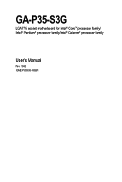
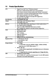
Block Diagram PCIe CLK (100 MHz) LGA775 Processor CPU CLK+/(333/266/200 MHz) Host Interface DDR2 1066/800/667 MHz PCI Express x16 ATA-133/100/66/33 IDE Channel PCI Express Bus 1 PCI Express x1 x 1 PCIe CLK (100 MHz) PCI Bus JMicron 368 x1 x1 RTL 8111B RJ45 LAN Intel® P35 Intel® ICH9 IT8208M CODEC Dual Channel Memory MCH CLK (333/266/200 MHz) BIOS 4 SATA 3Gb/s 12 USB Ports IT8718 Floppy LPT Port COM Port PS/2 KB/Mouse MIC (Center/Subwoofer Speaker Out) Line-Out (Front Speaker Out) Line-In (Rear Speaker Out) SPDIF Out 5 PCI PCI CLK (33 MHz) - 8 -
Block Diagram PCIe CLK (100 MHz) LGA775 Processor CPU CLK+/(333/266/200 MHz) Host Interface DDR2 1066/800/667 MHz PCI Express x16 ATA-133/100/66/33 IDE Channel PCI Express Bus 1 PCI Express x1 x 1 PCIe CLK (100 MHz) PCI Bus JMicron 368 x1 x1 RTL 8111B RJ45 LAN Intel® P35 Intel® ICH9 IT8208M CODEC Dual Channel Memory MCH CLK (333/266/200 MHz) BIOS 4 SATA 3Gb/s 12 USB Ports IT8718 Floppy LPT Port COM Port PS/2 KB/Mouse MIC (Center/Subwoofer Speaker Out) Line-Out (Front Speaker Out) Line-In (Rear Speaker Out) SPDIF Out 5 PCI PCI CLK (33 MHz) - 8 -
Manual
Page 10
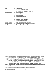
...Edition/Intel® Pentium® 4 processor/ Intel® Celeron® processor in the LGA 775 package (Go to GIGABYTE's website for the latest CPU support list.) Š L2 cache varies with CPU Š 1333/1066/800 MHz FSB Š...memory (Note 1) Š Dual channel memory architecture Š Support for DDR2 1066/800/667 MHz memory modules (Go to GIGABYTE's website for the latest memory support list.) Š Realtek AL662 codec Š High Definition Audio Š 2/4/5.1-channel Š...the back panel, 6 via the USB brackets connected to the internal USB headers) GA-P35-S3G Motherboard - 10 -
...Edition/Intel® Pentium® 4 processor/ Intel® Celeron® processor in the LGA 775 package (Go to GIGABYTE's website for the latest CPU support list.) Š L2 cache varies with CPU Š 1333/1066/800 MHz FSB Š...memory (Note 1) Š Dual channel memory architecture Š Support for DDR2 1066/800/667 MHz memory modules (Go to GIGABYTE's website for the latest memory support list.) Š Realtek AL662 codec Š High Definition Audio Š 2/4/5.1-channel Š...the back panel, 6 via the USB brackets connected to the internal USB headers) GA-P35-S3G Motherboard - 10 -
Manual
Page 12
GA-P35-S3G Motherboard - 12 - BIOS Unique Features Bundled Software Operating System Form Factor Š 1 x 8 Mbit flash Š Use of licensed AWARD BIOS Š PnP 1.0a, DMI 2.0, SM ...
GA-P35-S3G Motherboard - 12 - BIOS Unique Features Bundled Software Operating System Form Factor Š 1 x 8 Mbit flash Š Use of licensed AWARD BIOS Š PnP 1.0a, DMI 2.0, SM ...
Manual
Page 14
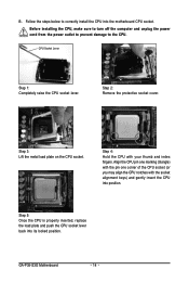
... CPU into its locked position. CPU Socket Lever Step 1: Completely raise the CPU socket lever. Step 3: Lift the metal load plate on the CPU socket. GA-P35-S3G Motherboard - 14 - Align the CPU pin one marking (triangle) with the pin one corner of the CPU socket (or you may align the CPU notches...
... CPU into its locked position. CPU Socket Lever Step 1: Completely raise the CPU socket lever. Step 3: Lift the metal load plate on the CPU socket. GA-P35-S3G Motherboard - 14 - Align the CPU pin one marking (triangle) with the pin one corner of the CPU socket (or you may align the CPU notches...
Manual
Page 16
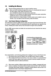
...) DDRII1 DDRII2 DDRII3 DDRII4 Due to chipset limitation, read the following guidelines before installing the memory in Flex Memory Mode will appear during the POST. GA-P35-S3G Motherboard - 16 - When memory modules of the same capacity, brand, speed, and chips be enabled if only one direction. Enabling Dual Channel memory mode will... - - The four DDR2 memory sockets are divided into two channels and each channel has two memory sockets as following guidelines before installing the memory to GIGABYTE's website for optimum performance.
...) DDRII1 DDRII2 DDRII3 DDRII4 Due to chipset limitation, read the following guidelines before installing the memory in Flex Memory Mode will appear during the POST. GA-P35-S3G Motherboard - 16 - When memory modules of the same capacity, brand, speed, and chips be enabled if only one direction. Enabling Dual Channel memory mode will... - - The four DDR2 memory sockets are divided into two channels and each channel has two memory sockets as following guidelines before installing the memory to GIGABYTE's website for optimum performance.
Manual
Page 18
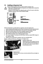
... push back on the lever on your expansion card. • Always turn off the computer and unplug the power cord from the chassis back panel. 2. GA-P35-S3G Motherboard - 18 - Align the card with the expansion card in the expansion slot. 1. Secure the card's metal bracket to prevent hardware damage. Carefully read the...
... push back on the lever on your expansion card. • Always turn off the computer and unplug the power cord from the chassis back panel. 2. GA-P35-S3G Motherboard - 18 - Align the card with the expansion card in the expansion slot. 1. Secure the card's metal bracket to prevent hardware damage. Carefully read the...

Manual
Page 20
GA-P35-S3G Motherboard - 20 - 1-7 Internal Connectors 1 12 4 3 7 2 5 13 14 1) ATX_12V 2) ATX 3) CPU_FAN 4) SYS_FAN1/SYS_FAN2 5) PWR_FAN 6) FDD 7) IDE 8) SATAII0/1/4/5 9) PWR_LED 8 10 4 9 6 16 15 17 11 10) BATTERY 11) ...
GA-P35-S3G Motherboard - 20 - 1-7 Internal Connectors 1 12 4 3 7 2 5 13 14 1) ATX_12V 2) ATX 3) CPU_FAN 4) SYS_FAN1/SYS_FAN2 5) PWR_FAN 6) FDD 7) IDE 8) SATAII0/1/4/5 9) PWR_LED 8 10 4 9 6 16 15 17 11 10) BATTERY 11) ...

Manual
Page 22
... the chassis. Most fans are designed with fan speed control design. The black connector wire is typically designated by a stripe of different color. 33 1 34 2 GA-P35-S3G Motherboard - 22 - For optimum heat dissipation, it in damage to connect a floppy disk drive. Overheating may result in the correct orientation. 3/4/5) CPU_FAN/SYS_FAN1/SYS_FAN2/PWR_FAN...
... the chassis. Most fans are designed with fan speed control design. The black connector wire is typically designated by a stripe of different color. 33 1 34 2 GA-P35-S3G Motherboard - 22 - For optimum heat dissipation, it in damage to connect a floppy disk drive. Overheating may result in the correct orientation. 3/4/5) CPU_FAN/SYS_FAN1/SYS_FAN2/PWR_FAN...
Manual
Page 24
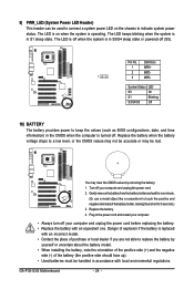
... the system is in the CMOS when the computer is turned off (S5). Gently remove the battery from the battery holder and wait for 5 seconds.) 3. GA-P35-S3G Motherboard - 24 - The LED is off when the system is in accordance with an equivalent one minute. (Or use a metal object like a screwdriver to indicate...
... the system is in the CMOS when the computer is turned off (S5). Gently remove the battery from the battery holder and wait for 5 seconds.) 3. GA-P35-S3G Motherboard - 24 - The LED is off when the system is in accordance with an equivalent one minute. (Or use a metal object like a screwdriver to indicate...
Manual
Page 26
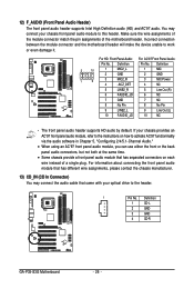
... 8 No Pin 9 LINE2_L 9 Line Out (L) 10 FAUDIO_JD 10 NC • The front panel audio header supports HD audio by default. Definition 1 CD-L 2 GND 3 GND 4 CD-R GA-P35-S3G Motherboard - 26 -
... 8 No Pin 9 LINE2_L 9 Line Out (L) 10 FAUDIO_JD 10 NC • The front panel audio header supports HD audio by default. Definition 1 CD-L 2 GND 3 GND 4 CD-R GA-P35-S3G Motherboard - 26 -

Manual
Page 28
.... To clear the CMOS values, place a jumper cap on your computer, be sure to factory defaults. This function requires a chassis with chassis intrusion detection design. GA-P35-S3G Motherboard - 28 - Definition 1 Signal 1 2 GND 17) CLR_CMOS (Clearing CMOS Jumper) Use this jumper to touch the two pins for BIOS configurations). Failure to do so...
.... To clear the CMOS values, place a jumper cap on your computer, be sure to factory defaults. This function requires a chassis with chassis intrusion detection design. GA-P35-S3G Motherboard - 28 - Definition 1 Signal 1 2 GND 17) CLR_CMOS (Clearing CMOS Jumper) Use this jumper to touch the two pins for BIOS configurations). Failure to do so...
Manual
Page 30
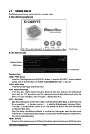
... you to set the first boot device without having to show the BIOS POST screen at system startup, refer to XpressRecovery2 during the POST. GA-P35-S3G Motherboard - 30 - In Boot Menu, use the up hard drive data using the motherboard driver disk, the key can access Boot Menu... restart, the device boot order will directly boot from the device configured in Boot Menu is effective for P35-S3G E8 . . . . : BIOS Setup/Q-Flash : XpressRecovery2 : Boot Menu : Qflash 11/05/2007-P35-ICH9-6A89OG0GC-00 Function Keys Function Keys: : POST Screen Press the key to enter BIOS Setup first....
... you to set the first boot device without having to show the BIOS POST screen at system startup, refer to XpressRecovery2 during the POST. GA-P35-S3G Motherboard - 30 - In Boot Menu, use the up hard drive data using the motherboard driver disk, the key can access Boot Menu... restart, the device boot order will directly boot from the device configured in Boot Menu is effective for P35-S3G E8 . . . . : BIOS Setup/Q-Flash : XpressRecovery2 : Boot Menu : Qflash 11/05/2007-P35-ICH9-6A89OG0GC-00 Function Keys Function Keys: : POST Screen Press the key to enter BIOS Setup first....

Manual
Page 32
... this menu to configure all peripheral devices, such as IDE, SATA, USB, integrated audio, and integrated LAN, etc. „ Power Management Setup Use this task.) GA-P35-S3G Motherboard - 32 - It allows you to save the current BIOS settings to the system and BIOS Setup. First enter the profile name (to erase the...
... this menu to configure all peripheral devices, such as IDE, SATA, USB, integrated audio, and integrated LAN, etc. „ Power Management Setup Use this task.) GA-P35-S3G Motherboard - 32 - It allows you to save the current BIOS settings to the system and BIOS Setup. First enter the profile name (to erase the...

Manual
Page 34
Drive A Allows you to selects the type of floppy disk drive installed in your hard drive specifications. GA-P35-S3G Motherboard - 34 - Cylinder Number of sectors. Sector Number of cylinders. Floppy 3 Mode Support Allows you do not install a floppy disk drive, set this item to ...
Drive A Allows you to selects the type of floppy disk drive installed in your hard drive specifications. GA-P35-S3G Motherboard - 34 - Cylinder Number of sectors. Sector Number of cylinders. Floppy 3 Mode Support Allows you do not install a floppy disk drive, set this item to ...
Manual
Page 36
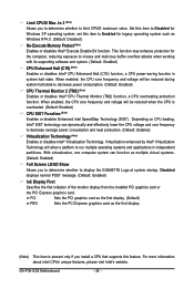
... the monitor display from the installed PCI graphics card or the PCI Express graphics card. GA-P35-S3G Motherboard - 36 - When enabled, the CPU core frequency and voltage will be reduced during system halt state to display the GIGABYTE Logo at system startup. This function may enhance protection for Windows XP operating system; set...
... the monitor display from the installed PCI graphics card or the PCI Express graphics card. GA-P35-S3G Motherboard - 36 - When enabled, the CPU core frequency and voltage will be reduced during system halt state to display the GIGABYTE Logo at system startup. This function may enhance protection for Windows XP operating system; set...
