
Manual
Page 7
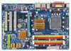
GA-P35-DS3L/S3L Motherboard Layout KB_MS COAXIAL OPTICAL ATX_12V LGA775 CPU_FAN ATX COM LPT DDRII1 GA-P35-DS3L/S3L R_USB SYS_FAN2 USB LAN F_AUDIO AUDIO SYS_FAN1 PCIE_3 RTL8111B PCIE_16 PCIE_1 SPDIF_O CODEC PCIE_2 SPDIF_I PCI1 PCI2 IT8718 PCI3 CD_IN Intel® P35 FDD DDRII3 DDRII4 DDRII2 PWR_FAN Intel® ICH9 BATTERY CLR_CMOS SATAII0 SATAII1 JMicron 368 SATAII4 BIOS SATAII5 IDE1 F_USB3 F_USB2 F_USB1 CI F_PANEL PWR_LED "*" Only the GA-P35-DS3L adopts All-Solid Capacitor design. - 7 -
GA-P35-DS3L/S3L Motherboard Layout KB_MS COAXIAL OPTICAL ATX_12V LGA775 CPU_FAN ATX COM LPT DDRII1 GA-P35-DS3L/S3L R_USB SYS_FAN2 USB LAN F_AUDIO AUDIO SYS_FAN1 PCIE_3 RTL8111B PCIE_16 PCIE_1 SPDIF_O CODEC PCIE_2 SPDIF_I PCI1 PCI2 IT8718 PCI3 CD_IN Intel® P35 FDD DDRII3 DDRII4 DDRII2 PWR_FAN Intel® ICH9 BATTERY CLR_CMOS SATAII0 SATAII1 JMicron 368 SATAII4 BIOS SATAII5 IDE1 F_USB3 F_USB2 F_USB1 CI F_PANEL PWR_LED "*" Only the GA-P35-DS3L adopts All-Solid Capacitor design. - 7 -
Manual
Page 8
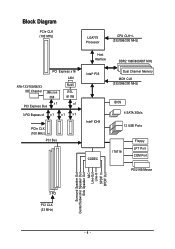
Block Diagram PCIe CLK (100 MHz) LGA775 Processor CPU CLK+/(333/266/200 MHz) PCI Express x16 LAN ATA-133/100/66/33 IDE Channel JMicron 368 x1 PCI Express Bus RJ45 RTL 8111B x1 3 PCI Express x1 x 1 x1 x1 PCIe CLK (100 MHz) PCI Bus Host Interface DDR2 1066/800/667 MHz Intel® P35 Dual Channel Memory MCH CLK (333/266/200 MHz) Intel® ICH9 BIOS 4 SATA 3Gb/s 12 USB Ports CODEC IT8718 Floppy LPT Port COM Port PS/2 KB/Mouse Surround Speaker Out Center/Subwoofer Speaker Out Side Speaker Out MIC Line-Out Line-In SPDIF In SPDIF Out 3 PCI PCI CLK (33 MHz) - 8 -
Block Diagram PCIe CLK (100 MHz) LGA775 Processor CPU CLK+/(333/266/200 MHz) PCI Express x16 LAN ATA-133/100/66/33 IDE Channel JMicron 368 x1 PCI Express Bus RJ45 RTL 8111B x1 3 PCI Express x1 x 1 x1 x1 PCIe CLK (100 MHz) PCI Bus Host Interface DDR2 1066/800/667 MHz Intel® P35 Dual Channel Memory MCH CLK (333/266/200 MHz) Intel® ICH9 BIOS 4 SATA 3Gb/s 12 USB Ports CODEC IT8718 Floppy LPT Port COM Port PS/2 KB/Mouse Surround Speaker Out Center/Subwoofer Speaker Out Side Speaker Out MIC Line-Out Line-In SPDIF In SPDIF Out 3 PCI PCI CLK (33 MHz) - 8 -
Manual
Page 10
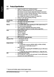
...Edition/Intel® Pentium® 4 processor/ Intel® Celeron® processor in the LGA 775 package (Go to GIGABYTE's website for the latest CPU support list.) Š Support for Intel® Hyper-Threading Technology Š L2 cache varies...: Intel® ICH9 Š 4 x 1.8V DDR2 DIMM sockets supporting up to 8 GB of system memory (Note 1) Š Dual channel memory architecture Š Support for DDR2 1066/800/667 MHz memory modules (Go to GIGABYTE's website for the...via the USB brackets connected to the internal USB headers) "*" Only the GA-P35-DS3L adopts All-Solid Capacitor design.
...Edition/Intel® Pentium® 4 processor/ Intel® Celeron® processor in the LGA 775 package (Go to GIGABYTE's website for the latest CPU support list.) Š Support for Intel® Hyper-Threading Technology Š L2 cache varies...: Intel® ICH9 Š 4 x 1.8V DDR2 DIMM sockets supporting up to 8 GB of system memory (Note 1) Š Dual channel memory architecture Š Support for DDR2 1066/800/667 MHz memory modules (Go to GIGABYTE's website for the...via the USB brackets connected to the internal USB headers) "*" Only the GA-P35-DS3L adopts All-Solid Capacitor design.
Manual
Page 12
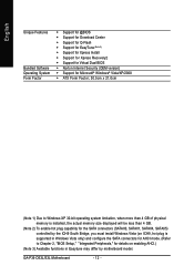
... be less than 4 GB. (Note 2) To enable hot plug capability for the SATA connectors (SATAII0, SATAII1, SATAII4, SATAII5) controlled by the ICH9 South Bridge, you must install Windows Vista (on ICH9, hot plug is supported in Windows Vista only) and configure the SATA connectors for AHCI mode. (Refer to Chapter 2, "BIOS Setup...
... be less than 4 GB. (Note 2) To enable hot plug capability for the SATA connectors (SATAII0, SATAII1, SATAII4, SATAII5) controlled by the ICH9 South Bridge, you must install Windows Vista (on ICH9, hot plug is supported in Windows Vista only) and configure the SATA connectors for AHCI mode. (Refer to Chapter 2, "BIOS Setup...
Manual
Page 24
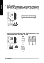
... device manufacturers.) 39 1 40 2 9) SATAII0/1/4/5 (SATA 3Gb/s Connectors, Controlled by ICH9) The SATA connectors conform to two IDE devices such as hard drives and optical drives. SATAII0 7 1 1 7 SATAII1 SATAII4 7 1 Pin No. 1 2 3 4 5 6 7 Definition GND TXP TXN GND RXN RXP GND 1 7 SATAII5 GA-P35-DS3L/S3L Motherboard - 24 - Each SATA connector supports a single SATA device. Before...
... device manufacturers.) 39 1 40 2 9) SATAII0/1/4/5 (SATA 3Gb/s Connectors, Controlled by ICH9) The SATA connectors conform to two IDE devices such as hard drives and optical drives. SATAII0 7 1 1 7 SATAII1 SATAII4 7 1 Pin No. 1 2 3 4 5 6 7 Definition GND TXP TXN GND RXN RXP GND 1 7 SATAII5 GA-P35-DS3L/S3L Motherboard - 24 - Each SATA connector supports a single SATA device. Before...
Manual
Page 32
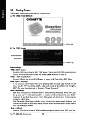
...Screen :BIOS Setup/Q-Flash :XpressRecovery2 :Boot Menu :Qflash Function Keys B. Motherboard Model BIOS Version Intel P35 BIOS for P35-DS3L F3a . . . . : BIOS Setup/Q-Flash : XpressRecovery2 : Boot Menu : Qflash 07/12/2007-P35-ICH9-6A79OG0TC-00 Function Keys Function Keys: : POST Screen Press the key to accept. To exit ... Boot Menu again to change the first boot device setting as needed. : Q-Flash Press the key to enter BIOS Setup first. GA-P35-DS3L/S3L Motherboard - 32 - For more information, refer to Chapter 4, "Xpress Recovery2." : Boot Menu Boot Menu allows you have ever...
...Screen :BIOS Setup/Q-Flash :XpressRecovery2 :Boot Menu :Qflash Function Keys B. Motherboard Model BIOS Version Intel P35 BIOS for P35-DS3L F3a . . . . : BIOS Setup/Q-Flash : XpressRecovery2 : Boot Menu : Qflash 07/12/2007-P35-ICH9-6A79OG0TC-00 Function Keys Function Keys: : POST Screen Press the key to accept. To exit ... Boot Menu again to change the first boot device setting as needed. : Q-Flash Press the key to enter BIOS Setup first. GA-P35-DS3L/S3L Motherboard - 32 - For more information, refer to Chapter 4, "Xpress Recovery2." : Boot Menu Boot Menu allows you have ever...

Manual
Page 60
... the Windows operating system. Xpress Recovery2 will begin to access Xpress Recovery2 for P35-DS3L F3a . . . . : BIOS Setup/Q-Flash : XpressRecovery2 : Boot Menu : Qflash 07/12/2007-P35-ICH9-6A79OG0TC-00 Figure 9 C. When the Windows operating system is detected, Xpress ...Recovery2 will then begin the backup process (Figure 11). Figure 10 Figure 11 3. Intel P35 BIOS for the first time. When finished, go to Disk Management to start backing up your hard drive. Figure 12 GA-P35-DS3L...
... the Windows operating system. Xpress Recovery2 will begin to access Xpress Recovery2 for P35-DS3L F3a . . . . : BIOS Setup/Q-Flash : XpressRecovery2 : Boot Menu : Qflash 07/12/2007-P35-ICH9-6A79OG0TC-00 Figure 9 C. When the Windows operating system is detected, Xpress ...Recovery2 will then begin the backup process (Figure 11). Figure 10 Figure 11 3. Intel P35 BIOS for the first time. When finished, go to Disk Management to start backing up your hard drive. Figure 12 GA-P35-DS3L...

Manual
Page 62
....TM GIGABYTE Q-Flash and @BIOS are easy-to-use and allow you can access Q-Flash by either pressing the key during the POST to access Q-Flash. What is Q-FlashTM? Intel P35 BIOS for P35-DS3L F3a . . . . : BIOS Setup/Q-Flash : XpressRecovery2 : Boot Menu : Qflash 07/12/2007-P35-ICH9-6A79OG0TC-...first. Before You Begin: 1. Restart the system. Inadequate BIOS flashing may result in BIOS Setup. p35ds3l.f1) to enter Q-Flash. GA-P35-DS3L/S3L Motherboard - 62 - Embedded in the Windows environment. @BIOS will download the latest BIOS file from the hassles of going through ...
....TM GIGABYTE Q-Flash and @BIOS are easy-to-use and allow you can access Q-Flash by either pressing the key during the POST to access Q-Flash. What is Q-FlashTM? Intel P35 BIOS for P35-DS3L F3a . . . . : BIOS Setup/Q-Flash : XpressRecovery2 : Boot Menu : Qflash 07/12/2007-P35-ICH9-6A79OG0TC-...first. Before You Begin: 1. Restart the system. Inadequate BIOS flashing may result in BIOS Setup. p35ds3l.f1) to enter Q-Flash. GA-P35-DS3L/S3L Motherboard - 62 - Embedded in the Windows environment. @BIOS will download the latest BIOS file from the hassles of going through ...
