Manual
Page 4
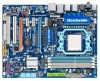
Table of Contents Box Contents ...6 OptionalItems ...6 GA-MA790XT-UD4P Motherboard Layout 7 Block Diagram ...8 Chapter 1 Hardware Installation 9 1-1 Installation Precautions 9 1-2 Product Specifications 10 1-3 Installing the CPU and CPU Cooler 13 1-3-1 Installing the CPU 13 1-3-2 Installing the CPU Cooler 15 1-4 Installing the Memory 16 1-4-1 Dual Channel Memory Configuration 16 1-4-2 Installing a Memory 17 1-5 Installing an Expansion Card 18 1-6 Configuring an ATI...
Table of Contents Box Contents ...6 OptionalItems ...6 GA-MA790XT-UD4P Motherboard Layout 7 Block Diagram ...8 Chapter 1 Hardware Installation 9 1-1 Installation Precautions 9 1-2 Product Specifications 10 1-3 Installing the CPU and CPU Cooler 13 1-3-1 Installing the CPU 13 1-3-2 Installing the CPU Cooler 15 1-4 Installing the Memory 16 1-4-1 Dual Channel Memory Configuration 16 1-4-2 Installing a Memory 17 1-5 Installing an Expansion Card 18 1-6 Configuring an ATI...
Manual
Page 8
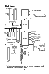
... x16 (Note) 2 PCIe x8 (Note) PCIe CLK (100 MHz) or AM3 CPU CPU CLK+/-(200 MHz) DDR3 1666(O.C.)/1333/1066 MHz Hyper Transport 3.0 Dual Channel Memory Switch PCI Express Bus PCI Express Bus x1 x1 x1 x1 PCIe CLK (100 MHz) 3 PCI Express x1 RJ45 RTL8111C/D(L) LAN 2 SATA 3Gb/s PCI Bus... GIGABYTE SATA2 TSB43AB23 AMD 790X AMD SB750 Dual BIOS 6 SATA 3Gb/s ATA-133/100/66/33 IDE Channel 12 USB Ports CODEC LPC BUS IT8720 Floppy ...
... x16 (Note) 2 PCIe x8 (Note) PCIe CLK (100 MHz) or AM3 CPU CPU CLK+/-(200 MHz) DDR3 1666(O.C.)/1333/1066 MHz Hyper Transport 3.0 Dual Channel Memory Switch PCI Express Bus PCI Express Bus x1 x1 x1 x1 PCIe CLK (100 MHz) 3 PCI Express x1 RJ45 RTL8111C/D(L) LAN 2 SATA 3Gb/s PCI Bus... GIGABYTE SATA2 TSB43AB23 AMD 790X AMD SB750 Dual BIOS 6 SATA 3Gb/s ATA-133/100/66/33 IDE Channel 12 USB Ports CODEC LPC BUS IT8720 Floppy ...

Manual
Page 9
... metal leads or connectors. • It is best to wear an electrostatic discharge (ESD) wrist strap when handling electronic components such as a motherboard, CPU or memory. Chapter 1 Hardware Installation 1-1 Installation Precautions The motherboard contains numerous delicate electronic circuits and components which can lead to damage to the local voltage standard. •...
... metal leads or connectors. • It is best to wear an electrostatic discharge (ESD) wrist strap when handling electronic components such as a motherboard, CPU or memory. Chapter 1 Hardware Installation 1-1 Installation Precautions The motherboard contains numerous delicate electronic circuits and components which can lead to damage to the local voltage standard. •...
Manual
Page 10
...; Support for Socket AM3 processors: AMD PhenomTM II X4 processor/AMD PhenomTM II X3 processor (Go to GIGABYTE's website for the latest CPU support list.) 5200 MT/s North Bridge: AMD 790X South Bridge: AMD SB750 4 ...DIMM sockets supporting up to 16 GB of system memory (Note 1) Dual channel memory architecture Support for DDR3 1666(O.C.)/1333/1066 MHz memory modules (Go to GIGABYTE's website for the latest memory support list.) Realtek ALC889A codec High Definition Audio...- 1 x floppy disk drive connector supporting up to the internal USB headers) GA-MA790XT-UD4P Motherboard - 10 -
...; Support for Socket AM3 processors: AMD PhenomTM II X4 processor/AMD PhenomTM II X3 processor (Go to GIGABYTE's website for the latest CPU support list.) 5200 MT/s North Bridge: AMD 790X South Bridge: AMD SB750 4 ...DIMM sockets supporting up to 16 GB of system memory (Note 1) Dual channel memory architecture Support for DDR3 1666(O.C.)/1333/1066 MHz memory modules (Go to GIGABYTE's website for the latest memory support list.) Realtek ALC889A codec High Definition Audio...- 1 x floppy disk drive connector supporting up to the internal USB headers) GA-MA790XT-UD4P Motherboard - 10 -

Manual
Page 12
... up to x8 mode. (Note 3) Whether the CPU/system fan speed control function is to install it in EasyTune may differ by motherboard model. GA-MA790XT-UD4P Motherboard - 12 - Unique Features Bundled Software Operating System Form Factor Support for @BIOS Support for Q-Flash Support for..., if only one PCI Express graphics card is supported will be sure to be installed, be less than 4 GB of physical memory is installed, the actual memory size displayed will depend on the CPU/ system cooler you install. (Note 4) Available functions in the PCIEX16_1 slot.
... up to x8 mode. (Note 3) Whether the CPU/system fan speed control function is to install it in EasyTune may differ by motherboard model. GA-MA790XT-UD4P Motherboard - 12 - Unique Features Bundled Software Operating System Form Factor Support for @BIOS Support for Q-Flash Support for..., if only one PCI Express graphics card is supported will be sure to be installed, be less than 4 GB of physical memory is installed, the actual memory size displayed will depend on the CPU/ system cooler you install. (Note 4) Available functions in the PCIEX16_1 slot.
Manual
Page 13
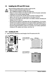
1-3 Installing the CPU and CPU Cooler Read the following guidelines before installing the CPU to GIGABYTE's website for the peripherals. Hardware Installation The CPU cannot be set the frequency beyond hardware specifications since it does not meet the ... the power outlet before you wish to set beyond the standard specifications, please do so according to your hardware specifications including the CPU, graphics card, memory, hard drive, etc. 1-3-1 Installing the CPU A. It is not installed, otherwise overheating and damage of the CPU. A Small Triangle Mark Denotes Pin ...
1-3 Installing the CPU and CPU Cooler Read the following guidelines before installing the CPU to GIGABYTE's website for the peripherals. Hardware Installation The CPU cannot be set the frequency beyond hardware specifications since it does not meet the ... the power outlet before you wish to set beyond the standard specifications, please do so according to your hardware specifications including the CPU, graphics card, memory, hard drive, etc. 1-3-1 Installing the CPU A. It is not installed, otherwise overheating and damage of the CPU. A Small Triangle Mark Denotes Pin ...
Manual
Page 16
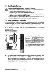
...outlet before installing the memory in Dual Channel mode. 1. DDR3_1 DDR3_2 DDR3_3 DDR3_4 Due to install the memory: • Make sure that memory of the same capacity, brand, speed, and chips be used . (Go to GIGABYTE's website for optimum ...memory. DS/SS DS/SS Four Modules DS/SS DS/SS DS/SS DS/SS (SS=Single-Sided, DS=Double-Sided, "- -"=No Memory) If two memory modules are divided into two channels and each channel has two memory sockets as following guidelines before installing the memory to prevent hardware damage. • Memory modules have a foolproof design. GA-MA790XT-UD4P...
...outlet before installing the memory in Dual Channel mode. 1. DDR3_1 DDR3_2 DDR3_3 DDR3_4 Due to install the memory: • Make sure that memory of the same capacity, brand, speed, and chips be used . (Go to GIGABYTE's website for optimum ...memory. DS/SS DS/SS Four Modules DS/SS DS/SS DS/SS DS/SS (SS=Single-Sided, DS=Double-Sided, "- -"=No Memory) If two memory modules are divided into two channels and each channel has two memory sockets as following guidelines before installing the memory to prevent hardware damage. • Memory modules have a foolproof design. GA-MA790XT-UD4P...

Manual
Page 17
...it can only fit in one direction. As indicated in the memory sockets. Place the memory module on the socket. Step 2: The clips at both ends of the memory module. Hardware Installation Follow the steps below to correctly install your memory modules in the picture on the left, place your fingers .... DDR3 and DDR2 DIMMs are not compatible to each other or DDR DIMMs. Be sure to the memory module. 1-4-2 Installing a Memory Before installing a memory module , make sure to turn off the computer and unplug the power cord from the power outlet to prevent damage to install DDR3...
...it can only fit in one direction. As indicated in the memory sockets. Place the memory module on the socket. Step 2: The clips at both ends of the memory module. Hardware Installation Follow the steps below to correctly install your memory modules in the picture on the left, place your fingers .... DDR3 and DDR2 DIMMs are not compatible to each other or DDR DIMMs. Be sure to the memory module. 1-4-2 Installing a Memory Before installing a memory module , make sure to turn off the computer and unplug the power cord from the power outlet to prevent damage to install DDR3...
Manual
Page 38
... CMOS and exit BIOS Setup. (Pressing can use the SPACE key) and then press to complete. F12 : Load CMOS from BIOS If your CPU, memory, etc. Standard CMOS Features Use this menu to configure the system time and date, hard drive types, floppy disk drive types, and the type... each profile. The Functions of your system becomes unstable and you have loaded the BIOS default settings, you can also carry out this task.) GA-MA790XT-UD4P Motherboard - 38 -
... CMOS and exit BIOS Setup. (Pressing can use the SPACE key) and then press to complete. F12 : Load CMOS from BIOS If your CPU, memory, etc. Standard CMOS Features Use this menu to configure the system time and date, hard drive types, floppy disk drive types, and the type... each profile. The Functions of your system becomes unstable and you have loaded the BIOS default settings, you can also carry out this task.) GA-MA790XT-UD4P Motherboard - 38 -

Manual
Page 39
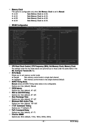
... Help F7: Optimized Defaults EC Firmware Selection Allows you set the System Voltage Control item to Auto to CPU, chipset, or memory and reduce the useful life of these components. 2-3 MB Intelligent Tweaker(M.I.T.) CMOS Setup Utility-Copyright (C) 1984-2009 Award Software MB...Ratio CPU NorthBridge Freq. CPU Host Clock Control x CPU Frequency (MHz) PCIE Clock (MHz) HT Link Width HT Link Frequency Set Memory Clock x Memory Clock DRAM Configuration ******** System Voltage Optimized System Voltage Control x DDR3 Voltage Control x NorthBridge Volt Control x SouthBridge Volt Control ...
... Help F7: Optimized Defaults EC Firmware Selection Allows you set the System Voltage Control item to Auto to CPU, chipset, or memory and reduce the useful life of these components. 2-3 MB Intelligent Tweaker(M.I.T.) CMOS Setup Utility-Copyright (C) 1984-2009 Award Software MB...Ratio CPU NorthBridge Freq. CPU Host Clock Control x CPU Frequency (MHz) PCIE Clock (MHz) HT Link Width HT Link Frequency Set Memory Clock x Memory Clock DRAM Configuration ******** System Voltage Optimized System Voltage Control x DDR3 Voltage Control x NorthBridge Volt Control x SouthBridge Volt Control ...
Manual
Page 40
...you to default values. The adjustable range is highly recommended that the CPU frequency be configurable. (Default: Auto) GA-MA790XT-UD4P Motherboard - 40 - Auto lets BIOS automatically set the memory clock as required. Manual allows the memory clock control item below to 200 MHz. Advanced Clock Calibration Allows you to automatically adjust the CPU host... HT Link between the CPU and chipset. Wait for a few seconds and the system will automatically restart for the settings to manually set the memory clock. Set Memory Clock Determines whether to take effect.
...you to default values. The adjustable range is highly recommended that the CPU frequency be configurable. (Default: Auto) GA-MA790XT-UD4P Motherboard - 40 - Auto lets BIOS automatically set the memory clock as required. Manual allows the memory clock control item below to 200 MHz. Advanced Clock Calibration Allows you to automatically adjust the CPU host... HT Link between the CPU and chipset. Wait for a few seconds and the system will automatically restart for the settings to manually set the memory clock. Set Memory Clock Determines whether to take effect.
Manual
Page 41
...: Fail-Safe Defaults ESC: Exit F1: General Help F7: Optimized Defaults CPU Host Clock Control, CPU Frequency (MHz), Set Memory Clock, Memory Clock The settings under the same items in the MB Intelligent Tweaker(M.I.T.). Row Precharge Time Options are synchronous to those under the...default), 4T~12T. Auto - - Options are : 90ns (default), 110ns, 160ns, 300ns, 350ns. - 41 - x8.00 Sets Memory Clock to be configurable. Unganged Sets memory control mode to two single-channel.(Default) DDR3 Timing Items Manual allows all DDR3 Timing items below to x8.00. CAS# latency...
...: Fail-Safe Defaults ESC: Exit F1: General Help F7: Optimized Defaults CPU Host Clock Control, CPU Frequency (MHz), Set Memory Clock, Memory Clock The settings under the same items in the MB Intelligent Tweaker(M.I.T.). Row Precharge Time Options are synchronous to those under the...default), 4T~12T. Auto - - Options are : 90ns (default), 110ns, 160ns, 300ns, 350ns. - 41 - x8.00 Sets Memory Clock to be configurable. Unganged Sets memory control mode to two single-channel.(Default) DDR3 Timing Items Manual allows all DDR3 Timing items below to x8.00. CAS# latency...

Manual
Page 42
... set memory voltage. CPU NB VID Control Allows you to set the South Bridge voltage. The adjustable range is dependent on the CPU being installed. (Default: Normal) Note: Increasing CPU voltage may result in damage to your CPU or reduce the useful life of the CPU. GA-MA790XT-UD4P Motherboard ...voltage by 0.050V to 0.3V at 0.1V increment. Write Recovery Time Options are : 90ns, 110ns, 160ns, 300ns, 350ns. Normal Supplies the memory voltage as required. CPU Voltage Control Allows you to set the system voltages as required. (Default) +0.050V ~ +0.750V Increases...
... set memory voltage. CPU NB VID Control Allows you to set the South Bridge voltage. The adjustable range is dependent on the CPU being installed. (Default: Normal) Note: Increasing CPU voltage may result in damage to your CPU or reduce the useful life of the CPU. GA-MA790XT-UD4P Motherboard ...voltage by 0.050V to 0.3V at 0.1V increment. Write Recovery Time Options are : 90ns, 110ns, 160ns, 300ns, 350ns. Normal Supplies the memory voltage as required. CPU Voltage Control Allows you to set the system voltages as required. (Default) +0.050V ~ +0.750V Increases...

Manual
Page 43
... Channel 4 Slave [None] [None] [None] [None] [None] [None] [None] [None] [None] [None] Drive A Floppy 3 Mode Support [1.44M, 3.5"] [Disabled] Halt On [All, But Keyboard] Base Memory Extended Memory Move Enter: Select F5: Previous Values 640K 510M +/-/PU/PD: Value F6: Fail-Safe Default F10: Save ESC: Exit F1: General Help F7: Optimized Defaults...
... Channel 4 Slave [None] [None] [None] [None] [None] [None] [None] [None] [None] [None] Drive A Floppy 3 Mode Support [1.44M, 3.5"] [Disabled] Halt On [All, But Keyboard] Base Memory Extended Memory Move Enter: Select F5: Previous Values 640K 510M +/-/PU/PD: Value F6: Fail-Safe Default F10: Save ESC: Exit F1: General Help F7: Optimized Defaults...

Manual
Page 44
...to specify whether the installed floppy disk drive is 3-mode floppy disk drive, a Japanese standard floppy disk drive. Extended Memory The amount of the currently installed hard drive. Sector Number of heads. All, But Keyboard The system boot will not ...Memory These fields are read-only and are determined by the BIOS POST. Typically, 640 KB will not stop . Cylinder Number of floppy disk drive installed in your hard drive specifications. Precomp Write precompensation cylinder. Floppy 3 Mode Support Allows you to the information on the hard drive. GA-MA790XT-UD4P...
...to specify whether the installed floppy disk drive is 3-mode floppy disk drive, a Japanese standard floppy disk drive. Extended Memory The amount of the currently installed hard drive. Sector Number of heads. All, But Keyboard The system boot will not ...Memory These fields are read-only and are determined by the BIOS POST. Typically, 640 KB will not stop . Cylinder Number of floppy disk drive installed in your hard drive specifications. Precomp Write precompensation cylinder. Floppy 3 Mode Support Allows you to the information on the hard drive. GA-MA790XT-UD4P...

Manual
Page 51
... the system to accept. Disabled Disables this function, you need an ATX power supply providing at which the system will be powered on the system. Memory The system returns to turn on automatically. Note: To use this function. (Default) Double Click Double click on left button on the PS/2 mouse to...
... the system to accept. Disabled Disables this function, you need an ATX power supply providing at which the system will be powered on the system. Memory The system returns to turn on automatically. Note: To use this function. (Default) Double Click Double click on left button on the PS/2 mouse to...
Manual
Page 61
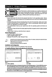
..., Windows® Vista • Xpress Recovery and Xpress Recovery2 are attached to quickly compress and back up your system data and perform restoration of system memory • VESA compatible graphics card • Windows® XP with Xpress Recovery cannot be restored using Xpress Recovery2. • USB hard drives are not supported...
..., Windows® Vista • Xpress Recovery and Xpress Recovery2 are attached to quickly compress and back up your system data and perform restoration of system memory • VESA compatible graphics card • Windows® XP with Xpress Recovery cannot be restored using Xpress Recovery2. • USB hard drives are not supported...
Manual
Page 68
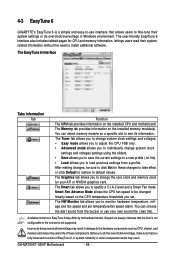
... to click Set for these components. The Memory tab provides information on the installed CPU and motherboard. GA-MA790XT-UD4P Motherboard - 68 - Grayed-out area(s) indicates that you to monitor hardware temperature, voltage and fan speed and set . You can choose the alert sound from a profile. 4-3 EasyTune 6 GIGABYTE's EasyTune 6 is not supported. The Smart tab...
... to click Set for these components. The Memory tab provides information on the installed CPU and motherboard. GA-MA790XT-UD4P Motherboard - 68 - Grayed-out area(s) indicates that you to monitor hardware temperature, voltage and fan speed and set . You can choose the alert sound from a profile. 4-3 EasyTune 6 GIGABYTE's EasyTune 6 is not supported. The Smart tab...

Manual
Page 75
... Micro Devices, Inc. [ Main Menu ] View Drive Assignments 1 ] Define LD 2 ] Delete LD 3 ] Controller Configuration 4 ] Press 1..4 to enter the Define LD window. Step 1: After the POST memory test begins and before the operating system boot begins, look for a message which says "Press to enter the RAID BIOS setup utility. Hit the + key...
... Micro Devices, Inc. [ Main Menu ] View Drive Assignments 1 ] Define LD 2 ] Delete LD 3 ] Controller Configuration 4 ] Press 1..4 to enter the Define LD window. Step 1: After the POST memory test begins and before the operating system boot begins, look for a message which says "Press to enter the RAID BIOS setup utility. Hit the + key...
Manual
Page 80
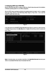
... up or down arrow key to configure a RAID array. PCIE-to enter RAID Setup Utility" (Figure 2). GIGABYTE Technology Corp. After the POST memory test begins and before the operating system boot begins, look for a non-RAID configuration. GA-MA790XT-UD4P Motherboard - 80 - Figure 2 In the main screen of Windows operating system for a message which says...
... up or down arrow key to configure a RAID array. PCIE-to enter RAID Setup Utility" (Figure 2). GIGABYTE Technology Corp. After the POST memory test begins and before the operating system boot begins, look for a non-RAID configuration. GA-MA790XT-UD4P Motherboard - 80 - Figure 2 In the main screen of Windows operating system for a message which says...


