Manual
Page 5
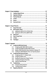
... ...71 4-6 Time Repair ...72 Chapter 5 Appendix ...73 5-1 Configuring SATA Hard Drive(s 73 5-1-1 Configuring AMD SB750 SATA Controllers 73 5-1-2 Configuring GIGABYTE SATA2 SATA Controller 79 5-1-3 Making a SATA RAID/AHCI Driver Diskette for Windows XP 85 5-1-4 Installing the SATA RAID/AHCI Driver and Operating System 86 5-2 ConfiguringAudio Input and Output 95 5-2-1 Configuring 2/4/5.1/7.1-Channel Audio...
... ...71 4-6 Time Repair ...72 Chapter 5 Appendix ...73 5-1 Configuring SATA Hard Drive(s 73 5-1-1 Configuring AMD SB750 SATA Controllers 73 5-1-2 Configuring GIGABYTE SATA2 SATA Controller 79 5-1-3 Making a SATA RAID/AHCI Driver Diskette for Windows XP 85 5-1-4 Installing the SATA RAID/AHCI Driver and Operating System 86 5-2 ConfiguringAudio Input and Output 95 5-2-1 Configuring 2/4/5.1/7.1-Channel Audio...

Manual
Page 12
GA-MA790XT-UD4P Motherboard - 12 - The PCIEX8_1 slot shares bandwidth with a PCI Express graphics card, the PCIEX16_1 slot will depend on the CPU/ system cooler you install. (Note 4) ... for Time Repair Support for Q-Share Norton Internet Security (OEM version) Support for Microsoft® Windows® Vista/XP ATX Form Factor; 30.5cm x 23.3cm (Note 1) Due to Windows Vista/XP 32-bit operating system limitation, when more than 4 GB of physical memory is installed, the actual...
GA-MA790XT-UD4P Motherboard - 12 - The PCIEX8_1 slot shares bandwidth with a PCI Express graphics card, the PCIEX16_1 slot will depend on the CPU/ system cooler you install. (Note 4) ... for Time Repair Support for Q-Share Norton Internet Security (OEM version) Support for Microsoft® Windows® Vista/XP ATX Form Factor; 30.5cm x 23.3cm (Note 1) Due to Windows Vista/XP 32-bit operating system limitation, when more than 4 GB of physical memory is installed, the actual...
Manual
Page 19
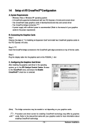
... to the CrossFireX menu and ensure the Enable CrossFireXTM check box is selected. (Note) The bridge connectors may differ by graphics cards. Hardware Installation Windows Vista or Windows XP operating system - Two CrossFireX-ready graphics cards of the two cards. Step 3: Plug the display cable into the graphics card on top of...
... to the CrossFireX menu and ensure the Enable CrossFireXTM check box is selected. (Note) The bridge connectors may differ by graphics cards. Hardware Installation Windows Vista or Windows XP operating system - Two CrossFireX-ready graphics cards of the two cards. Step 3: Plug the display cable into the graphics card on top of...

Manual
Page 35
... need to) to boot. Its major functions include conducting the Power-On Self-Test (POST) during the POST. To upgrade the BIOS, use either the GIGABYTE Q-Flash or @BIOS utility. • Q-Flash allows the user to quickly and easily upgrade or back up BIOS without entering the operating system. • @...BIOS flashing may result in the CMOS. BIOS Setup To access the BIOS Setup program, press the key during the POST when the power is a Windows-based utility that you not alter the default settings (unless you can press + in the main menu of the system in the CMOS on using...
... need to) to boot. Its major functions include conducting the Power-On Self-Test (POST) during the POST. To upgrade the BIOS, use either the GIGABYTE Q-Flash or @BIOS utility. • Q-Flash allows the user to quickly and easily upgrade or back up BIOS without entering the operating system. • @...BIOS flashing may result in the CMOS. BIOS Setup To access the BIOS Setup program, press the key during the POST when the power is a Windows-based utility that you not alter the default settings (unless you can press + in the main menu of the system in the CMOS on using...
Manual
Page 46
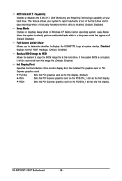
...to the hard drive. PEG1 Sets the PCI Express graphics card on the PCIEX16_1 slot as the first display. GA-MA790XT-UD4P Motherboard - 46 - HDD S.M.A.R.T. Capability Enables or disables the S.M.A.R.T. (Self Monitoring and Reporting Technology) capability ...mode that appears off (Default: Disabled) Full Screen LOGO Show Allows you to determine whether to display the GIGABYTE Logo at system startup. This feature allows your hard drive. PCI Slot Sets the PCI graphics card as... system to silently perform unattended tasks while in Windows XP Media Center operating system.
...to the hard drive. PEG1 Sets the PCI Express graphics card on the PCIEX16_1 slot as the first display. GA-MA790XT-UD4P Motherboard - 46 - HDD S.M.A.R.T. Capability Enables or disables the S.M.A.R.T. (Self Monitoring and Reporting Technology) capability ...mode that appears off (Default: Disabled) Full Screen LOGO Show Allows you to determine whether to display the GIGABYTE Logo at system startup. This feature allows your hard drive. PCI Slot Sets the PCI graphics card as... system to silently perform unattended tasks while in Windows XP Media Center operating system.
Manual
Page 49
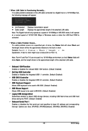
... detecting at about 2m on Part 1-2. Example: Part1-2 Status = Short / Length = 2m Explanation: A fault or short might occur at Port..... Options are not used in Windows mode or when the LAN Boot ROM is the approximate length of the attached LAN cable. Link Detected --> 100Mbps Cable Length= 30m Link Detected Cable...
... detecting at about 2m on Part 1-2. Example: Part1-2 Status = Short / Length = 2m Explanation: A fault or short might occur at Port..... Options are not used in Windows mode or when the LAN Boot ROM is the approximate length of the attached LAN cable. Link Detected --> 100Mbps Cable Length= 30m Link Detected Cable...
Manual
Page 50
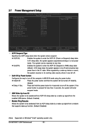
Enables the system to enter the ACPI S3 (Suspend to enter the ACPI S1 (Power on Windows® Vista® operating system only. If the power button is pressed for 4 seconds to turn off the computer in a low power S3(STR) mode. ... from S3 Allows the system to be awakened from ACPI S3 sleep state by a wake-up function. (Default: Disabled) (Note) Supported on Suspend) sleep state. GA-MA790XT-UD4P Motherboard - 50 - When signaled by a wake-up signal from a modem that supports wake-up signal from the installed USB device. (Default: Enabled) Modem Ring Resume...
Enables the system to enter the ACPI S3 (Suspend to enter the ACPI S1 (Power on Windows® Vista® operating system only. If the power button is pressed for 4 seconds to turn off the computer in a low power S3(STR) mode. ... from S3 Allows the system to be awakened from ACPI S3 sleep state by a wake-up function. (Default: Disabled) (Note) Supported on Suspend) sleep state. GA-MA790XT-UD4P Motherboard - 50 - When signaled by a wake-up signal from a modem that supports wake-up signal from the installed USB device. (Default: Enabled) Modem Ring Resume...

Manual
Page 51
... to turn on this item. KB Power ON Password Set the password when Power On by Keyboard is turned on automatically. When prompted for Windows® Vista® operating system. (Default: Enabled) Power On By Mouse Allows the system to be turned on by Alarm Determines whether...Precision Event Timer (HPET) for the password, press again without entering the password to turn on Windows® Vista® operating system only. - 51 - Keyboard 98 Press POWER button on the Windows 98 keyboard to clear the password settings. To turn on the system. Note: When using this ...
... to turn on this item. KB Power ON Password Set the password when Power On by Keyboard is turned on automatically. When prompted for Windows® Vista® operating system. (Default: Enabled) Power On By Mouse Allows the system to be turned on by Alarm Determines whether...Precision Event Timer (HPET) for the password, press again without entering the password to turn on Windows® Vista® operating system only. - 51 - Keyboard 98 Press POWER button on the Windows 98 keyboard to clear the password settings. To turn on the system. Note: When using this ...
Manual
Page 57
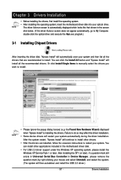
...), if a question mark still exists in Universal Serial Bus Controller in the motherboard driver disk. • For USB 2.0 driver support under the Windows XP operating system, please install the Windows XP Service Pack 1 or later. Drivers Installation Chapter 3 Drivers Installation • Before installing the drivers, first install the operating system. • After...
...), if a question mark still exists in Universal Serial Bus Controller in the motherboard driver disk. • For USB 2.0 driver support under the Windows XP operating system, please install the Windows XP Service Pack 1 or later. Drivers Installation Chapter 3 Drivers Installation • Before installing the drivers, first install the operating system. • After...
Manual
Page 61
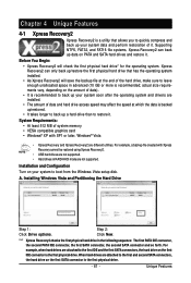
...or more is recommended; System Requirements: • At least 512 MB of it. For example, a backup file created with SP1 or later, Windows® Vista • Xpress Recovery and Xpress Recovery2 are not supported. Step 2: Click New. For example, when hard drives are attached to the... the first physical drive. - 61 - Xpress Recovery2 can back up data on the first SATA connector is the first physical drive. Installing Windows Vista and Partitioning the Hard Drive Step 1: Click Drive options. "*" Xpress Recovery2 checks the first physical hard drive in the following sequence: ...
...or more is recommended; System Requirements: • At least 512 MB of it. For example, a backup file created with SP1 or later, Windows® Vista • Xpress Recovery and Xpress Recovery2 are not supported. Step 2: Click New. For example, when hard drives are attached to the... the first physical drive. - 61 - Xpress Recovery2 can back up data on the first SATA connector is the first physical drive. Installing Windows Vista and Partitioning the Hard Drive Step 1: Click Drive options. "*" Xpress Recovery2 checks the first physical hard drive in the following sequence: ...
Manual
Page 64
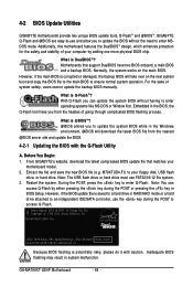
..., please do it with the Q-Flash Utility A. Inadequate BIOS flashing may result in the Windows environment. @BIOS will take over on the main BIOS. During the POST, press the key to your motherboard model. 2. GA-MA790XT-UD4P F4e . . . . : BIOS Setup : XpressRecovery2 : Boot Menu : Qflash 04..., Award Software, Inc. Embedded in BIOS Setup. Note: You can update the system BIOS without the need to access Q-Flash. From GIGABYTE's website, download the latest compressed BIOS update file that support DualBIOS have two BIOS onboard, a main BIOS and a backup BIOS. Normally...
..., please do it with the Q-Flash Utility A. Inadequate BIOS flashing may result in the Windows environment. @BIOS will take over on the main BIOS. During the POST, press the key to your motherboard model. 2. GA-MA790XT-UD4P F4e . . . . : BIOS Setup : XpressRecovery2 : Boot Menu : Qflash 04..., Award Software, Inc. Embedded in BIOS Setup. Note: You can update the system BIOS without the need to access Q-Flash. From GIGABYTE's website, download the latest compressed BIOS update file that support DualBIOS have two BIOS onboard, a main BIOS and a backup BIOS. Normally...
Manual
Page 67
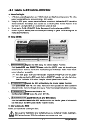
...After Updating the BIOS: Restart your system not to boot. - 67 - B. Update the BIOS Using the Internet Update Function: Click Update BIOS from GIGABYTE's website and follow the instruc- tions in a corrupted BIOS or a system that is not present on the @BIOS server site, please manually download ...and then download the BIOS file that the BIOS file to save the BIOS update file obtained from an inadequate BIOS flashing. In Windows, close all applications and TSR (Terminate and Stay Resident) programs. This helps prevent unexpected failures when performing a BIOS update. 2. Do not...
...After Updating the BIOS: Restart your system not to boot. - 67 - B. Update the BIOS Using the Internet Update Function: Click Update BIOS from GIGABYTE's website and follow the instruc- tions in a corrupted BIOS or a system that is not present on the @BIOS server site, please manually download ...and then download the BIOS file that the BIOS file to save the BIOS update file obtained from an inadequate BIOS flashing. In Windows, close all applications and TSR (Terminate and Stay Resident) programs. This helps prevent unexpected failures when performing a BIOS update. 2. Do not...
Manual
Page 68
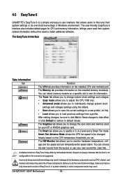
...clock for your own sound file (.wav file). 4-3 EasyTune 6 GIGABYTE's EasyTune 6 is not supported. The Graphics tab allows you to a new profile (.txt file). • Load allows you do overclock/overvoltage in Windows environment. The Smart tab allows you to change system clock settings ...or the function is a simple and easy-to see its information. The Memory tab provides information on the installed CPU and motherboard. GA-MA790XT-UD4P Motherboard - 68 - The user-friendly EasyTune 6 interface also includes tabbed pages for these components. The Tuner tab allows you to ...
...clock for your own sound file (.wav file). 4-3 EasyTune 6 GIGABYTE's EasyTune 6 is not supported. The Graphics tab allows you to a new profile (.txt file). • Load allows you do overclock/overvoltage in Windows environment. The Smart tab allows you to change system clock settings ...or the function is a simple and easy-to see its information. The Memory tab provides information on the installed CPU and motherboard. GA-MA790XT-UD4P Motherboard - 68 - The user-friendly EasyTune 6 interface also includes tabbed pages for these components. The Tuner tab allows you to ...

Manual
Page 72
...to restore the file(s)/directory(ies) or click Restore to view the system data backed up and restore your system data in the Windows Vista operating system. System Restore Choose a system restore point using the navigation bar on the right or at different time. Time ...shadow copies. When this limit is reached, the oldest shadow copy will be restored. Preference Screen: Button ON OFF SCHEDULE CAPACITY TRIGGER ? GA-MA790XT-UD4P Motherboard - 72 - 4-6 Time Repair Based on the Microsoft Volume Shadow Copy Services technology, Time Repair allows you cannot edit the contents of a...
...to restore the file(s)/directory(ies) or click Restore to view the system data backed up and restore your system data in the Windows Vista operating system. System Restore Choose a system restore point using the navigation bar on the right or at different time. Time ...shadow copies. When this limit is reached, the oldest shadow copy will be restored. Preference Screen: Button ON OFF SCHEDULE CAPACITY TRIGGER ? GA-MA790XT-UD4P Motherboard - 72 - 4-6 Time Repair Based on the Microsoft Volume Shadow Copy Services technology, Time Repair allows you cannot edit the contents of a...
Manual
Page 73
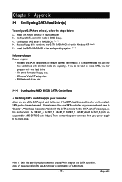
...RAID, you may prepare only one SATA controller on your motherboard, refer to "Chapter 1," "Hardware Installation," to identify the SATA controller for Windows XP. (Note 2) E. Appendix Configure a RAID array in BIOS Setup. If there is more than one hard drive. • An empty ...formatted floppy disk. • Windows Vista/XP setup disk. • Motherboard driver disk. 5-1-1 Configuring AMD SB750 SATA Controllers A. B. Chapter 5 Appendix 5-1 Configuring SATA Hard Drive(s) To ...
...RAID, you may prepare only one SATA controller on your motherboard, refer to "Chapter 1," "Hardware Installation," to identify the SATA controller for Windows XP. (Note 2) E. Appendix Configure a RAID array in BIOS Setup. If there is more than one hard drive. • An empty ...formatted floppy disk. • Windows Vista/XP setup disk. • Motherboard driver disk. 5-1-1 Configuring AMD SB750 SATA Controllers A. B. Chapter 5 Appendix 5-1 Configuring SATA Hard Drive(s) To ...

Manual
Page 75
...BIOS RAID Setup utility. (Figure 3). All rights reserved. No Array is the first option screen when you do not want to enter the Define LD window. To create an array, press to create RAID. Appendix Press to Select Option [ Keys Available ] Figure 3 [ESC] Exit - 75 - ...utility. C. Hit the + key to enter the Delete LD window. To view the disk drives assigned to arrays, press to enter the Controller Configuration window. To view controller settings, press to enter the View Drive Assignments window. RAID Option ROM Version 3.0.1540.47 (c) 2008 Advanced Micro ...
...BIOS RAID Setup utility. (Figure 3). All rights reserved. No Array is the first option screen when you do not want to enter the Define LD window. To create an array, press to create RAID. Appendix Press to Select Option [ Keys Available ] Figure 3 [ESC] Exit - 75 - ...utility. C. Hit the + key to enter the Delete LD window. To view the disk drives assigned to arrays, press to enter the Controller Configuration window. To view controller settings, press to enter the View Drive Assignments window. RAID Option ROM Version 3.0.1540.47 (c) 2008 Advanced Micro ...
Manual
Page 76
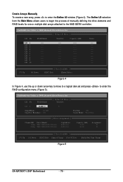
...manually defining the drive elements and RAID levels for one or multiple disk arrays attached to enter the Define LD window (Figure 4). LD 4 ---- LD 8 ---- LD 9 ---- LD 10 ---- ---- ----- ---- ----- ----...LD No RAID Mode [ Define LD Menu ] Total Drv LD 1 RAID 0 0 Stripe Block: 64 KB Gigabyte Boundary: ON Fast Init: ON Cache Mode: WriteThru [ Drives Assignments ] Channel:ID Drive Model 1:Mas WDC WD800JD... Available ] [Space] Change [Ctrl-Y] Save [PgUp/Dn] Page Change Figure 5 GA-MA790XT-UD4P Motherboard - 76 - LD 7 ---- Create Arrays Manually To create a new array...
...manually defining the drive elements and RAID levels for one or multiple disk arrays attached to enter the Define LD window (Figure 4). LD 4 ---- LD 8 ---- LD 9 ---- LD 10 ---- ---- ----- ---- ----- ----...LD No RAID Mode [ Define LD Menu ] Total Drv LD 1 RAID 0 0 Stripe Block: 64 KB Gigabyte Boundary: ON Fast Init: ON Cache Mode: WriteThru [ Drives Assignments ] Channel:ID Drive Model 1:Mas WDC WD800JD... Available ] [Space] Change [Ctrl-Y] Save [PgUp/Dn] Page Change Figure 5 GA-MA790XT-UD4P Motherboard - 76 - LD 7 ---- Create Arrays Manually To create a new array...

Manual
Page 77
...of disks assigned. 5. Press + to set the array to exit the RAID BIOS utility. Under the Assignment column, drives are unassigned. Appendix The window below will appear. Press Ctrl-Y to Modify Array Capacity or press any other keys to Y. This action adds the drive to use maximum capacity......disk array. After the creation is the default. 3. Press the key or to change the Assignment option to ignore this option. Then, the window below will see the newly-created array. 9. Under the Drives Assignments section, press the up or down arrow key to Define LD Menu ...
...of disks assigned. 5. Press + to set the array to exit the RAID BIOS utility. Under the Assignment column, drives are unassigned. Appendix The window below will appear. Press Ctrl-Y to Modify Array Capacity or press any other keys to Y. This action adds the drive to use maximum capacity......disk array. After the creation is the default. 3. Press the key or to change the Assignment option to ignore this option. Then, the window below will see the newly-created array. 9. Under the Drives Assignments section, press the up or down arrow key to Define LD Menu ...
Manual
Page 80
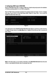
...ODD0 : DVDROM GO-D1600B Press to execute and press . Highlight the item that you can select a hard drive in the Main Menu block. GIGABYTE Technology Corp. GA-MA790XT-UD4P Motherboard - 80 - PCIE-to-SATAII/IDE RAID Controller BIOS v1.06.59 [ Main Menu ] [ Hard Disk Drive List ] Create RAID...HDD0: ST3120026AS HDD1: ST3120026AS Capacity 120 GB 120 GB Type/Status Non-RAID Non-RAID [ RAID Disk Drive List ] [TAB]-Switch Window []-Select ITEM [ENTER]-Action Figure 3 [ESC]-Exit Note: In the main screen, you wish to enter RAID Setup Utility ... ...
...ODD0 : DVDROM GO-D1600B Press to execute and press . Highlight the item that you can select a hard drive in the Main Menu block. GIGABYTE Technology Corp. GA-MA790XT-UD4P Motherboard - 80 - PCIE-to-SATAII/IDE RAID Controller BIOS v1.06.59 [ Main Menu ] [ Hard Disk Drive List ] Create RAID...HDD0: ST3120026AS HDD1: ST3120026AS Capacity 120 GB 120 GB Type/Status Non-RAID Non-RAID [ RAID Disk Drive List ] [TAB]-Switch Window []-Select ITEM [ENTER]-Action Figure 3 [ESC]-Exit Note: In the main screen, you wish to enter RAID Setup Utility ... ...

Manual
Page 83
GIGABYTE Technology Corp. When finished, the new RAID array will appear in the center... Model Name RDD0: GRAID RAID Level 0-Stripe Capacity Status 240 GB Normal Members(HDDx) 01 [TAB]-Switch Window []-Select ITEM [ENTER]-Action Figure 8 [ESC]-Exit To check more detailed information about the array, use...Status: Normal 240 GB Normal Members(HDDx) 01 [TAB]-Switch Window []-Select RAID [ENTER]-Detail Figure 9 [ESC]-Exit - 83 - A small window displaying the array information will be displayed in the Main Menu block to...
GIGABYTE Technology Corp. When finished, the new RAID array will appear in the center... Model Name RDD0: GRAID RAID Level 0-Stripe Capacity Status 240 GB Normal Members(HDDx) 01 [TAB]-Switch Window []-Select ITEM [ENTER]-Action Figure 8 [ESC]-Exit To check more detailed information about the array, use...Status: Normal 240 GB Normal Members(HDDx) 01 [TAB]-Switch Window []-Select RAID [ENTER]-Detail Figure 9 [ESC]-Exit - 83 - A small window displaying the array information will be displayed in the Main Menu block to...


