Manual
Page 1
GA-MA78GPM-DS2H/ GA-MA78GM-DS2H AM2+/AM2 socket motherboard for AMD PhenomTM FX processor/AMD PhenomTM X4 processor/ AMD PhenomTM X3 processor/AMD AthlonTM X2 processor/ AMD AthlonTM processor/AMD SempronTM X2 processor/ AMD SempronTM processor User's Manual Rev. 1003 12ME-MA78GPM2H-1003R
GA-MA78GPM-DS2H/ GA-MA78GM-DS2H AM2+/AM2 socket motherboard for AMD PhenomTM FX processor/AMD PhenomTM X4 processor/ AMD PhenomTM X3 processor/AMD AthlonTM X2 processor/ AMD AthlonTM processor/AMD SempronTM X2 processor/ AMD SempronTM processor User's Manual Rev. 1003 12ME-MA78GPM2H-1003R
Manual
Page 3
...the Support\Motherboard\Technology Guide page on our website. Documentation Classifications In order to assist in this : "REV: X.X." GIGABYTE UNITED INC. sive global distributor of the motherboard is designated by copyright laws and is exclusively licensed to the specifications and...; For instructions on your motherboard revision before updating motherboard BIOS, drivers, or when looking for technical information. No part of GIGABYTE. The logo is the property of this manual may be reproduced, copied, translated, transmitted, or published in this manual is...
...the Support\Motherboard\Technology Guide page on our website. Documentation Classifications In order to assist in this : "REV: X.X." GIGABYTE UNITED INC. sive global distributor of the motherboard is designated by copyright laws and is exclusively licensed to the specifications and...; For instructions on your motherboard revision before updating motherboard BIOS, drivers, or when looking for technical information. No part of GIGABYTE. The logo is the property of this manual may be reproduced, copied, translated, transmitted, or published in this manual is...
Manual
Page 4
Table of Contents Box Contents ...6 OptionalItems ...6 GA-MA78GPM-DS2H/GA-MA78GM-DS2H Motherboard Layout 7 Block Diagram ...8 Chapter 1 Hardware Installation 9 1-1 Installation Precautions 9 1-2 Product Specifications 10 1-3 Installing the CPU and CPU Cooler 13 1-3-1 Installing the CPU 13 1-3-2 Installing the ...
Table of Contents Box Contents ...6 OptionalItems ...6 GA-MA78GPM-DS2H/GA-MA78GM-DS2H Motherboard Layout 7 Block Diagram ...8 Chapter 1 Hardware Installation 9 1-1 Installation Precautions 9 1-2 Product Specifications 10 1-3 Installing the CPU and CPU Cooler 13 1-3-1 Installing the CPU 13 1-3-2 Installing the ...
Manual
Page 5
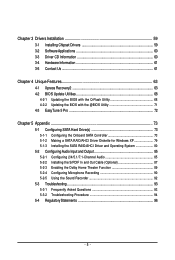
Chapter 3 Drivers Installation 59 3-1 Installing Chipset Drivers 59 3-2 SoftwareApplications 60 3-3 Driver CD Information 60 3-4 Hardware Information 61 3-5 Contact Us ...61 Chapter 4 Unique Features 63 4-1 Xpress Recovery2 63 4-2 BIOS Update Utilities 68 4-2-1 Updating the BIOS with the Q-Flash Utility 68 4-2-2 Updating the BIOS with the @BIOS Utility 71 4-3 EasyTune 5 Pro 72 Chapter 5 Appendix ...73 5-1 Configuring SATA Hard Drive(s 73 5-1-1 Configuring the Onboard SATA Controller 73 5-1-2 Making a SATA RAID/AHCI Driver Diskette for Windows XP 79 5-1-3 Installing the SATA RAID/...
Chapter 3 Drivers Installation 59 3-1 Installing Chipset Drivers 59 3-2 SoftwareApplications 60 3-3 Driver CD Information 60 3-4 Hardware Information 61 3-5 Contact Us ...61 Chapter 4 Unique Features 63 4-1 Xpress Recovery2 63 4-2 BIOS Update Utilities 68 4-2-1 Updating the BIOS with the Q-Flash Utility 68 4-2-2 Updating the BIOS with the @BIOS Utility 71 4-3 EasyTune 5 Pro 72 Chapter 5 Appendix ...73 5-1 Configuring SATA Hard Drive(s 73 5-1-1 Configuring the Onboard SATA Controller 73 5-1-2 Making a SATA RAID/AHCI Driver Diskette for Windows XP 79 5-1-3 Installing the SATA RAID/...
Manual
Page 6
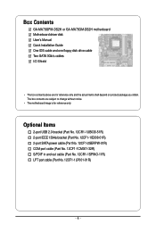
... No. 12CF1-1CM001-32R) S/PDIF in and out cable (Part No. 12CR1-1SPINO-11R) LPT port cable (Part No. 12CF1-1LP001-01R) - 6 - Box Contents GA-MA78GPM-DS2H or GA-MA78GM-DS2H motherboard Motherboard driver disk User's Manual Quick Installation Guide One IDE cable and one floppy disk drive cable Two SATA 3Gb/s cables I/O Shield •...
... No. 12CF1-1CM001-32R) S/PDIF in and out cable (Part No. 12CR1-1SPINO-11R) LPT port cable (Part No. 12CF1-1LP001-01R) - 6 - Box Contents GA-MA78GPM-DS2H or GA-MA78GM-DS2H motherboard Motherboard driver disk User's Manual Quick Installation Guide One IDE cable and one floppy disk drive cable Two SATA 3Gb/s cables I/O Shield •...
Manual
Page 7
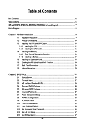
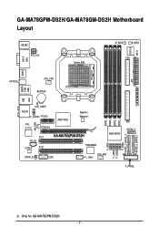
GA-MA78GPM-DS2H/GA-MA78GM-DS2H Motherboard Layout DVI-D VGA KB_MS ATX_12V Socket AM2 M_BIOS B_BIOS IT8718 CI FDD HDMI ATX OPTICAL ESATA 1394 USB CPU_FAN BATTERY LAN USB CLR_CMOS AUDIO F_AUDIO PCIEX1 RTL 8111C PCIEX16 AMD 780G SidePort Memory NB_FAN PCI1 CD_IN CODEC PCI2 GA-MA78G(P)M-DS2H TSB43AB23 AMD SB700 SPDIF_IO COM F1_1394 SYS_FAN F_USB1 F_USB2 F_USB3 F_USB4 SATA2_2 SATA2_3 DDR2_1 DDR2_2 DDR2_3 DDR2_4 LPT IDE SATA2_4 PWR_LED SATA2_0 SATA2_1 F_PANEL Only for GA-MA78GPM-DS2H. - 7 -
GA-MA78GPM-DS2H/GA-MA78GM-DS2H Motherboard Layout DVI-D VGA KB_MS ATX_12V Socket AM2 M_BIOS B_BIOS IT8718 CI FDD HDMI ATX OPTICAL ESATA 1394 USB CPU_FAN BATTERY LAN USB CLR_CMOS AUDIO F_AUDIO PCIEX1 RTL 8111C PCIEX16 AMD 780G SidePort Memory NB_FAN PCI1 CD_IN CODEC PCI2 GA-MA78G(P)M-DS2H TSB43AB23 AMD SB700 SPDIF_IO COM F1_1394 SYS_FAN F_USB1 F_USB2 F_USB3 F_USB4 SATA2_2 SATA2_3 DDR2_1 DDR2_2 DDR2_3 DDR2_4 LPT IDE SATA2_4 PWR_LED SATA2_0 SATA2_1 F_PANEL Only for GA-MA78GPM-DS2H. - 7 -
Manual
Page 8
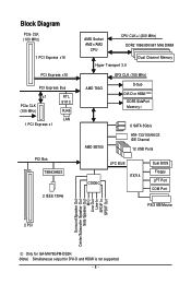
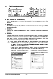
... PS/2 KB/Mouse 2 PCI Surround Speaker Out Center/Subwoofer Speaker Out Side Speaker Out MIC Line-Out Line-In SPDIF In SPDIF Out Only for GA-MA78GPM-DS2H. (Note) Simultaneous output for DVI-D and HDMI is not supported. - 8 -
... PS/2 KB/Mouse 2 PCI Surround Speaker Out Center/Subwoofer Speaker Out Side Speaker Out MIC Line-Out Line-In SPDIF In SPDIF Out Only for GA-MA78GPM-DS2H. (Note) Simultaneous output for DVI-D and HDMI is not supported. - 8 -
Manual
Page 9
If you are connected tightly and securely. • When handling the motherboard, avoid touching any installation steps or have it on top of an antistatic pad or within an electrostatic shielding container. • Before unplugging the power supply cable from the power outlet before installing or removing the motherboard or other hardware components. • When connecting hardware components to the internal connectors on the motherboard, make sure the power supply voltage has been set according to the local voltage standard. • Before using the product, please verify that all ...
If you are connected tightly and securely. • When handling the motherboard, avoid touching any installation steps or have it on top of an antistatic pad or within an electrostatic shielding container. • Before unplugging the power supply cable from the power outlet before installing or removing the motherboard or other hardware components. • When connecting hardware components to the internal connectors on the motherboard, make sure the power supply voltage has been set according to the local voltage standard. • Before using the product, please verify that all ...
Manual
Page 10
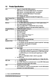
TSB43AB23 chip Up to 2 IEEE 1394a ports (1 on the back panel, 1 via the USB brackets connected to the internal USB headers) Only for GA-MA78GPM-DS2H. 1-2 Product Specifications CPU Š Hyper Transport Bus Š Chipset Š Š Memory Š Š Š Intergrated Memory Š Audio &#...system memory (Note 1) Dual channel memory architecture Support for DDR2 1066 (Note 2)/800/667 MHz memory modules (Go to GIGABYTE's website for the latest memory support list.) 128MB DDR3 SidePort memory Realtek ALC889A codec High Definition Audio 2/4/5.1/7.1-channel Support for ...
TSB43AB23 chip Up to 2 IEEE 1394a ports (1 on the back panel, 1 via the USB brackets connected to the internal USB headers) Only for GA-MA78GPM-DS2H. 1-2 Product Specifications CPU Š Hyper Transport Bus Š Chipset Š Š Memory Š Š Š Intergrated Memory Š Audio &#...system memory (Note 1) Dual channel memory architecture Support for DDR2 1066 (Note 2)/800/667 MHz memory modules (Go to GIGABYTE's website for the latest memory support list.) 128MB DDR3 SidePort memory Realtek ALC889A codec High Definition Audio 2/4/5.1/7.1-channel Support for ...
Manual
Page 11
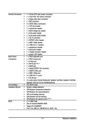
Hardware Installation Internal Connectors Š 1 x 24-pin ATX main power connector Š 1 x 4-pin ATX 12V power connector Š 1 x floppy disk drive connector Š 1 x IDE connector Š 5 x SATA 3Gb/s connectors Š 1 x CPU fan header Š 1 x system fan header Š 1 x North Bridge fan header Š 1 x front panel header Š 1 x front panel audio header Š 1 x CD In connector Š 1 x S/PDIF In/Out header Š 1 x IEEE 1394a header Š 4 x USB 2.0/1.1 headers Š 1 x parallel port header Š 1 x serial port header Š 1 x chassis ...
Hardware Installation Internal Connectors Š 1 x 24-pin ATX main power connector Š 1 x 4-pin ATX 12V power connector Š 1 x floppy disk drive connector Š 1 x IDE connector Š 5 x SATA 3Gb/s connectors Š 1 x CPU fan header Š 1 x system fan header Š 1 x North Bridge fan header Š 1 x front panel header Š 1 x front panel audio header Š 1 x CD In connector Š 1 x S/PDIF In/Out header Š 1 x IEEE 1394a header Š 4 x USB 2.0/1.1 headers Š 1 x parallel port header Š 1 x serial port header Š 1 x chassis ...
Manual
Page 12
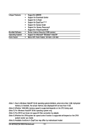
GA-MA78G(P)M-DS2H Motherboard - 12 - Unique Features Bundled Software Operating System Form Factor Š Support for @BIOS Š Support for Download Center Š Support for Q-Flash Š Support ...
GA-MA78G(P)M-DS2H Motherboard - 12 - Unique Features Bundled Software Operating System Form Factor Š Support for @BIOS Š Support for Download Center Š Support for Q-Flash Š Support ...
Manual
Page 13
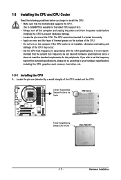
Locate the pin one of the CPU. mended that the motherboard supports the CPU. (Go to GIGABYTE's website for the peripherals. A Small Triangle Mark Denotes Pin One of the Socket AM2 Socket A Small Triangle Marking Denotes CPU Pin One AM2+/AM2 CPU - ...
Locate the pin one of the CPU. mended that the motherboard supports the CPU. (Go to GIGABYTE's website for the peripherals. A Small Triangle Mark Denotes Pin One of the Socket AM2 Socket A Small Triangle Marking Denotes CPU Pin One AM2+/AM2 CPU - ...
Manual
Page 14
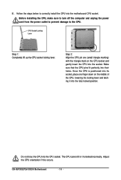
... CPU pin one finger down on the CPU socket and gently insert the CPU into the socket. Do not force the CPU into their holes. GA-MA78G(P)M-DS2H Motherboard - 14 - Follow the steps below to the CPU. Before installing the CPU, make sure to turn off the computer and unplug the power...
... CPU pin one finger down on the CPU socket and gently insert the CPU into the socket. Do not force the CPU into their holes. GA-MA78G(P)M-DS2H Motherboard - 14 - Follow the steps below to the CPU. Before installing the CPU, make sure to turn off the computer and unplug the power...
Manual
Page 15
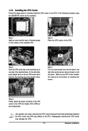
... on the CPU. 1-3-2 Installing the CPU Cooler Follow the steps below to correctly install the CPU cooler on the CPU. (The following procedure uses the GIGABYTE cooler as the picture above shows) to lock into place. (Refer to your CPU cooler installation manual for instructions on installing the cooler.) Step 5: Finally...
... on the CPU. 1-3-2 Installing the CPU Cooler Follow the steps below to correctly install the CPU cooler on the CPU. (The following procedure uses the GIGABYTE cooler as the picture above shows) to lock into place. (Refer to your CPU cooler installation manual for instructions on installing the cooler.) Step 5: Finally...
Manual
Page 16
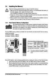
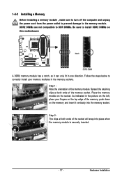
...or four memory modules, it is recommended that memory of the same capacity, brand, speed, and chips be used . (Go to GIGABYTE's website for optimum performance. 1-4 Installing the Memory Read the following guidelines before you begin to install the memory: • Make ... modules have a foolproof design. It is recommended that you install them in Dual Channel mode. 1. After the memory is installed. 2. GA-MA78G(P)M-DS2H Motherboard - 16 - A memory module can be enabled if only one direction. Enabling Dual Channel memory mode will automatically detect the specifications and...
...or four memory modules, it is recommended that memory of the same capacity, brand, speed, and chips be used . (Go to GIGABYTE's website for optimum performance. 1-4 Installing the Memory Read the following guidelines before you begin to install the memory: • Make ... modules have a foolproof design. It is recommended that you install them in Dual Channel mode. 1. After the memory is installed. 2. GA-MA78G(P)M-DS2H Motherboard - 16 - A memory module can be enabled if only one direction. Enabling Dual Channel memory mode will automatically detect the specifications and...
Manual
Page 17
Step 1: Note the orientation of the memory socket. Place the memory module on the memory and insert it can only fit in the memory sockets. Step 2: The clips at both ends of the memory, push down on the socket. Hardware Installation Notch DDR2 DIMM A DDR2 memory module has a notch, so it vertically into place when the memory module is securely inserted. - 17 - As indicated in the picture on the left, place your memory modules in one direction. Follow the steps below to install DDR2 DIMMs on this motherboard. DDR2 DIMMs are not compatible to DDR DIMMs. Be sure to...
Step 1: Note the orientation of the memory socket. Place the memory module on the memory and insert it can only fit in the memory sockets. Step 2: The clips at both ends of the memory, push down on the socket. Hardware Installation Notch DDR2 DIMM A DDR2 memory module has a notch, so it vertically into place when the memory module is securely inserted. - 17 - As indicated in the picture on the left, place your memory modules in one direction. Follow the steps below to install DDR2 DIMMs on this motherboard. DDR2 DIMMs are not compatible to DDR DIMMs. Be sure to...

Manual
Page 18
... slot. Example: Installing and Removing a PCI Express x16 Graphics Card: • Installing a Graphics Card: Gently push down on your expansion card in the slot. 3. GA-MA78G(P)M-DS2H Motherboard - 18 - Install the driver provided with a screw. 5. Make sure the card is fully inserted into the slot. 4. PCI Express x1 Slot PCI Express x16...
... slot. Example: Installing and Removing a PCI Express x16 Graphics Card: • Installing a Graphics Card: Gently push down on your expansion card in the slot. 3. GA-MA78G(P)M-DS2H Motherboard - 18 - Install the driver provided with a screw. 5. Make sure the card is fully inserted into the slot. 4. PCI Express x1 Slot PCI Express x16...
Manual
Page 19
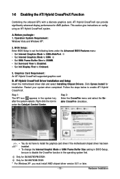
... icon appears in BIOS Setup, be sure to enter the Catalyst Control Center. Only for GA-MA78GPM-DS2H. ATI Hybrid CrossFireX Driver Installation and Setup Insert the motherboard driver disk and select Installing Chipset Drivers. Only for GA-MA78GM-DS2H. * For Windows XP, you begin-1. Follow the steps below to Onboard. 3. Hardware Installation BIOS Setup...
... icon appears in BIOS Setup, be sure to enter the Catalyst Control Center. Only for GA-MA78GPM-DS2H. ATI Hybrid CrossFireX Driver Installation and Setup Insert the motherboard driver disk and select Installing Chipset Drivers. Only for GA-MA78GM-DS2H. * For Windows XP, you begin-1. Follow the steps below to Onboard. 3. Hardware Installation BIOS Setup...
Manual
Page 20
.... (The item name may differ by operating system. In Windows Vista, select Start>Control Panel> Sound, select Realtek HDMI Output and then click Set Default. GA-MA78G(P)M-DS2H Motherboard - 20 - Connect a monitor that supports D-Sub connection to D-SUB/ HDMI under Advanced BIOS Features. • Please note the HDMI audio output only supports...
.... (The item name may differ by operating system. In Windows Vista, select Start>Control Panel> Sound, select Realtek HDMI Output and then click Set Default. GA-MA78G(P)M-DS2H Motherboard - 20 - Connect a monitor that supports D-Sub connection to D-SUB/ HDMI under Advanced BIOS Features. • Please note the HDMI audio output only supports...
Manual
Page 21
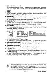
USB Port The USB port supports the USB 2.0/1.1 specification. Use this audio jack for USB devices such as an optical drive, walkman, etc. RJ-45 LAN Port The Gigabit Ethernet LAN port provides Internet connection at up to a back panel connector, first remove the cable from your audio system provides an optical digital audio in connector. Side Speaker Out Jack (Gray) Use this audio jack to connect center/subwoofer speakers in a 5.1/7.1-channel audio configuration. Use this port for a headphone or 2-channel speaker. Use this feature, ensure that supports ...
USB Port The USB port supports the USB 2.0/1.1 specification. Use this audio jack for USB devices such as an optical drive, walkman, etc. RJ-45 LAN Port The Gigabit Ethernet LAN port provides Internet connection at up to a back panel connector, first remove the cable from your audio system provides an optical digital audio in connector. Side Speaker Out Jack (Gray) Use this audio jack to connect center/subwoofer speakers in a 5.1/7.1-channel audio configuration. Use this port for a headphone or 2-channel speaker. Use this feature, ensure that supports ...
