Manual
Page 4
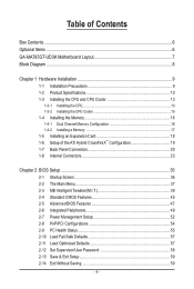
Table of Contents Box Contents...6 Optional Items...6 GA-MA785GT-UD3H Motherboard Layout 7 Block Diagram...8 Chapter 1 Hardware Installation 9 1-1 Installation Precautions 9 1-2 Product Specifications 10 1-3 Installing the CPU and CPU Cooler 13 1-3-1 Installing the CPU 13 1-3-2 Installing the CPU Cooler 15 1-4 Installing the Memory 16 1-4-1 Dual Channel Memory Configuration 16 1-4-2 Installing a Memory 17 1-5 Installing an Expansion Card 18 1-6 Setup of...
Table of Contents Box Contents...6 Optional Items...6 GA-MA785GT-UD3H Motherboard Layout 7 Block Diagram...8 Chapter 1 Hardware Installation 9 1-1 Installation Precautions 9 1-2 Product Specifications 10 1-3 Installing the CPU and CPU Cooler 13 1-3-1 Installing the CPU 13 1-3-2 Installing the CPU Cooler 15 1-4 Installing the Memory 16 1-4-1 Dual Channel Memory Configuration 16 1-4-2 Installing a Memory 17 1-5 Installing an Expansion Card 18 1-6 Setup of...
Manual
Page 8
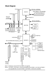
... x1 RTL8111C PCIe CLK (100 MHz) 3 PCI Express x1 (Note 2) RJ45 LAN AM3 CPU CPU CLK+/- (200 MHz) DDR3 1666(O.C.)/1333/1066 MHz Dual Channel Memory Hyper Transport 3.0 GFX CLK (100 MHz) AMD 785G D-Sub DVI-D or HDMI (Note 1) 6 SATA 3Gb/s ATA-133/100/66/33 IDE Channel PCI Bus TSB43AB23...
... x1 RTL8111C PCIe CLK (100 MHz) 3 PCI Express x1 (Note 2) RJ45 LAN AM3 CPU CPU CLK+/- (200 MHz) DDR3 1666(O.C.)/1333/1066 MHz Dual Channel Memory Hyper Transport 3.0 GFX CLK (100 MHz) AMD 785G D-Sub DVI-D or HDMI (Note 1) 6 SATA 3Gb/s ATA-133/100/66/33 IDE Channel PCI Bus TSB43AB23...
Manual
Page 9
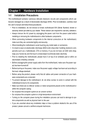
... components. • When connecting hardware components to the internal connectors on the computer power during the installation process can become damaged as a motherboard, CPU or memory. Prior to installation, carefully read the user's manual and follow these procedures: • Prior to the use of the product, please consult a certified computer technician...
... components. • When connecting hardware components to the internal connectors on the computer power during the installation process can become damaged as a motherboard, CPU or memory. Prior to installation, carefully read the user's manual and follow these procedures: • Prior to the use of the product, please consult a certified computer technician...
Manual
Page 10
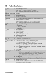
...up to 2 IDE devices - 6 x SATA 3Gb/s connectors supporting up to 16 GB of system memory (Note 1) Dual channel memory architecture Support for DDR3 1666(O.C.)/1333/1066 MHz memory modules (Go to GIGABYTE's website for the latest CPU support list.) 5200 MT/s North Bridge: AMD 785G South Bridge: AMD ...Expansion Slots Storage Interface USB Support for AM3 processors: AMD Phenom™ II processor/ AMD Athlon™ II processor (Go to GIGABYTE's website for the latest memory support list.) Integrated in the South Bridge Up to 12 USB 2.0/1.1 ports (6 on the back panel, 6 via the USB ...
...up to 2 IDE devices - 6 x SATA 3Gb/s connectors supporting up to 16 GB of system memory (Note 1) Dual channel memory architecture Support for DDR3 1666(O.C.)/1333/1066 MHz memory modules (Go to GIGABYTE's website for the latest CPU support list.) 5200 MT/s North Bridge: AMD 785G South Bridge: AMD ...Expansion Slots Storage Interface USB Support for AM3 processors: AMD Phenom™ II processor/ AMD Athlon™ II processor (Go to GIGABYTE's website for the latest memory support list.) Integrated in the South Bridge Up to 12 USB 2.0/1.1 ports (6 on the back panel, 6 via the USB ...
Manual
Page 12
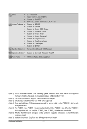
... Form Factor; 30.5cm x 22.9cm (Note 1) Due to Windows Vista/XP 32-bit operating system limitation, when more than 4 GB of physical memory is installed, the actual memory size displayed will depend on the CPU/system cooler you are installing a PCI Express graphics card, be less than 4 GB. (Note 2) The DVI...
... Form Factor; 30.5cm x 22.9cm (Note 1) Due to Windows Vista/XP 32-bit operating system limitation, when more than 4 GB of physical memory is installed, the actual memory size displayed will depend on the CPU/system cooler you are installing a PCI Express graphics card, be less than 4 GB. (Note 2) The DVI...
Manual
Page 13
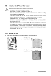
...off the computer and unplug the power cord from the power outlet before installing the CPU to your hardware specifications including the CPU, graphics card, memory, hard drive, etc. 1-3-1 Installing the CPU A. It is not installed, otherwise overheating and dam- The CPU cannot be set the frequency ...CPU support list.) • Always turn on the computer if the CPU cooler is not recommended that the motherboard supports the CPU. (Go to GIGABYTE's website for the peripherals. Locate the pin one of the Socket AM3 Socket A Small Triangle Marking Denotes CPU Pin One AM3 CPU - 13 ...
...off the computer and unplug the power cord from the power outlet before installing the CPU to your hardware specifications including the CPU, graphics card, memory, hard drive, etc. 1-3-1 Installing the CPU A. It is not installed, otherwise overheating and dam- The CPU cannot be set the frequency ...CPU support list.) • Always turn on the computer if the CPU cooler is not recommended that the motherboard supports the CPU. (Go to GIGABYTE's website for the peripherals. Locate the pin one of the Socket AM3 Socket A Small Triangle Marking Denotes CPU Pin One AM3 CPU - 13 ...
Manual
Page 16
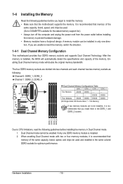
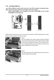
... one direction. DDR3_1 DDR3_2 DDR3_3 DDR3_4 Due to CPU limitations, read the following guidelines before installing the memory in only one DDR3 memory module is installed. 2. A memory module can be used . (Go to GIGABYTE's website for the latest memory support list.) • Always turn off the computer and unplug the power cord from the power...
... one direction. DDR3_1 DDR3_2 DDR3_3 DDR3_4 Due to CPU limitations, read the following guidelines before installing the memory in only one DDR3 memory module is installed. 2. A memory module can be used . (Go to GIGABYTE's website for the latest memory support list.) • Always turn off the computer and unplug the power cord from the power...
Manual
Page 17
... has a notch, so it can only fit in the picture on the memory and insert it vertically into place when the memory module is securely inserted. - 17 - Place the memory module on this motherboard. Hardware Installation Follow the steps below to correctly install your fingers on the top ...indicated in one direction. DDR3 and DDR2 DIMMs are not compatible to each other or DDR DIMMs. Be sure to the memory module. 1-4-2 Installing a Memory Before installing a memory module, make sure to turn off the computer and unplug the power cord from the power outlet to prevent damage to install...
... has a notch, so it can only fit in the picture on the memory and insert it vertically into place when the memory module is securely inserted. - 17 - Place the memory module on this motherboard. Hardware Installation Follow the steps below to correctly install your fingers on the top ...indicated in one direction. DDR3 and DDR2 DIMMs are not compatible to each other or DDR DIMMs. Be sure to the memory module. 1-4-2 Installing a Memory Before installing a memory module, make sure to turn off the computer and unplug the power cord from the power outlet to prevent damage to install...
Manual
Page 21
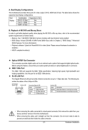
... discs, refer to the recommended system requirements (or better) below shows the supported dual display configurations. Hardware Installation The table below . • Memory: Two 1 GB DDR3 1066 MHz memory modules with dual channel mode enabled • BIOS Setup: At least 256 MB of the LAN port LEDs. A. Before using this port for...
... discs, refer to the recommended system requirements (or better) below shows the supported dual display configurations. Hardware Installation The table below . • Memory: Two 1 GB DDR3 1066 MHz memory modules with dual channel mode enabled • BIOS Setup: At least 256 MB of the LAN port LEDs. A. Before using this port for...
Manual
Page 38
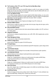
... loaded the BIOS default settings, you can use the SPACE key) and then press to complete. F12: Load CMOS from BIOS If your CPU, memory, etc. Standard CMOS Features Use this menu to configure the system time and date, hard drive types, floppy disk drive types, and the type...
... loaded the BIOS default settings, you can use the SPACE key) and then press to complete. F12: Load CMOS from BIOS If your CPU, memory, etc. Standard CMOS Features Use this menu to configure the system time and date, hard drive types, floppy disk drive types, and the type...
Manual
Page 39
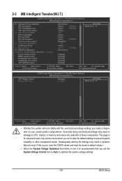
...to optimize the system voltage settings. - 39 - Incorrectly doing overclock/overvoltage may result in damage to CPU, chipset, or memory and reduce the useful life of these components. If this occurs, clear the CMOS values and reset the board to default ... Frequency(MHz) PCIE Clock(MHz) HT Link Width HT Link Frequency VGA Core Clock control x VGA Core Clock(MHz) Set Memory Clock x Memory Clock } DRAM Configuration ******** System Voltage Optimized ******** System Voltage Control DDR3 Voltage Control NorthBridge Volt Control SouthBridge Volt Control CPU NB...
...to optimize the system voltage settings. - 39 - Incorrectly doing overclock/overvoltage may result in damage to CPU, chipset, or memory and reduce the useful life of these components. If this occurs, clear the CMOS values and reset the board to default ... Frequency(MHz) PCIE Clock(MHz) HT Link Width HT Link Frequency VGA Core Clock control x VGA Core Clock(MHz) Set Memory Clock x Memory Clock } DRAM Configuration ******** System Voltage Optimized ******** System Voltage Control DDR3 Voltage Control NorthBridge Volt Control SouthBridge Volt Control CPU NB...
Manual
Page 41
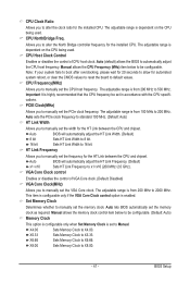
...X4.00. This item is configurable only if the VGA Core Clock control option is dependent on the CPU being used . X4.00 Sets Memory Clock to manually set in accordance with the CPU specifications. Allows you to be configurable. Manual allows the CPU Frequency (MHz) item below...of VGA Core clock. (Default: Disabled) VGA Core Clock(MHz) Allows you to manually set the CPU host frequency. Manual allows the memory clock control item below to alter the North Bridge controller frequency for the HT Link between the CPU and chipset. Auto BIOS will automatically adjust...
...X4.00. This item is configurable only if the VGA Core Clock control option is dependent on the CPU being used . X4.00 Sets Memory Clock to manually set in accordance with the CPU specifications. Allows you to be configurable. Manual allows the CPU Frequency (MHz) item below...of VGA Core clock. (Default: Disabled) VGA Core Clock(MHz) Allows you to manually set the CPU host frequency. Manual allows the memory clock control item below to alter the North Bridge controller frequency for the HT Link between the CPU and chipset. Auto BIOS will automatically adjust...
Manual
Page 42
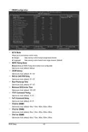
CAS# latency Options are : Auto (default), 5T~12T. Row Precharge Time Options are : Auto (default), 4T~12T. Ganged Sets memory control mode to set memory control mode. TwTr Command Delay Options are : Auto (default), 90ns, 110ns, 160ns, 300ns, 350ns. Trfc0 for DIMM2 Options are : Auto (default), ... F7: Optimized Defaults DCTs Mode Allows you to single dual-channel. Trfc2 for DIMM1 Options are : Auto (default), 4T~7T. Unganged Sets memory control mode to two single-channel. (Default) DDR3 Timing Items Manual allows all DDR3 Timing items below to be configurable. RAS to CAS ...
CAS# latency Options are : Auto (default), 5T~12T. Row Precharge Time Options are : Auto (default), 4T~12T. Ganged Sets memory control mode to set memory control mode. TwTr Command Delay Options are : Auto (default), 90ns, 110ns, 160ns, 300ns, 350ns. Trfc0 for DIMM2 Options are : Auto (default), ... F7: Optimized Defaults DCTs Mode Allows you to single dual-channel. Trfc2 for DIMM1 Options are : Auto (default), 4T~7T. Unganged Sets memory control mode to two single-channel. (Default) DDR3 Timing Items Manual allows all DDR3 Timing items below to be configurable. RAS to CAS ...
Manual
Page 43
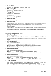
...Auto (default), 90ns, 110ns, 160ns, 300ns, 350ns. Enabled allows the system to simultaneously access different channels of the memory to increase memory performance and stability. (Default: Enabled) ******** System Voltage Optimized ******** System Voltage Control Determines whether to set the system voltages.... Normal Supplies the South Bridge voltage as required. Normal Supplies the memory voltage as required. (Default) +0.050V ~ +0.750V Increases memory voltage by 0.1V to set the system voltages as required. (Default) -0.1V ~ +0.2V ...
...Auto (default), 90ns, 110ns, 160ns, 300ns, 350ns. Enabled allows the system to simultaneously access different channels of the memory to increase memory performance and stability. (Default: Enabled) ******** System Voltage Optimized ******** System Voltage Control Determines whether to set the system voltages.... Normal Supplies the South Bridge voltage as required. Normal Supplies the memory voltage as required. (Default) +0.050V ~ +0.750V Increases memory voltage by 0.1V to set the system voltages as required. (Default) -0.1V ~ +0.2V ...

Manual
Page 45
... 3 Master } IDE Channel 3 Slave [None] [None] [None] [None] [None] [None] [None] [None] Drive A Floppy 3 Mode Support [1.44M, 3.5"] [Disabled] Halt On [All, But Keyboard] Base Memory Extended Memory 640K 510M Move Enter: Select F5: Previous Values +/-/PU/PD: Value F10: Save F6: Fail-Safe Defaults ESC: Exit F1: General Help F7: Optimized Defaults...
... 3 Master } IDE Channel 3 Slave [None] [None] [None] [None] [None] [None] [None] [None] Drive A Floppy 3 Mode Support [1.44M, 3.5"] [Disabled] Halt On [All, But Keyboard] Base Memory Extended Memory 640K 510M Move Enter: Select F5: Previous Values +/-/PU/PD: Value F10: Save F6: Fail-Safe Defaults ESC: Exit F1: General Help F7: Optimized Defaults...
Manual
Page 46
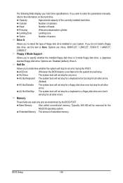
...Allows you to select the type of the currently installed hard drive. No Errors The system boot will stop for all other errors. Memory These fields are read-only and are : Disabled (default), Drive A. Head Number of sectors. Halt On Allows you do not install... 2.88M/3.5". Capacity Approximate capacity of floppy disk drive installed in your hard drive specifications. The following fields display your system. Base Memory Also called conventional memory. All, But Disk/Key The system boot will not stop for a keyboard or a floppy disk drive error but stop . If...
...Allows you to select the type of the currently installed hard drive. No Errors The system boot will stop for all other errors. Memory These fields are read-only and are : Disabled (default), Drive A. Head Number of sectors. Halt On Allows you do not install... 2.88M/3.5". Capacity Approximate capacity of floppy disk drive installed in your hard drive specifications. The following fields display your system. Base Memory Also called conventional memory. All, But Disk/Key The system boot will not stop for a keyboard or a floppy disk drive error but stop . If...
Manual
Page 47
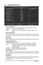
...the onboard graphics controller. troller. When enabled, the CPU core frequency and voltage will use only this memory for the onboard graphics controller. UMA Allocates memory for the onboard graphics controller from the D-SUB/DVI-D or D-SUB/HDMI. Surround View Enables or ... F6: Fail-Safe Defaults ESC: Exit F1: General Help F7: Optimized Defaults Internal Graphics Mode Allows you to determine whether to allocate system memory for display. Options are: Auto (default), 128MB, 256MB, 512MB. D-SUB/HDMI Sets the D-SUB/HDMI as multiple virtual systems. (Default...
...the onboard graphics controller. troller. When enabled, the CPU core frequency and voltage will use only this memory for the onboard graphics controller. UMA Allocates memory for the onboard graphics controller from the D-SUB/DVI-D or D-SUB/HDMI. Surround View Enables or ... F6: Fail-Safe Defaults ESC: Exit F1: General Help F7: Optimized Defaults Internal Graphics Mode Allows you to determine whether to allocate system memory for display. Options are: Auto (default), 128MB, 256MB, 512MB. D-SUB/HDMI Sets the D-SUB/HDMI as multiple virtual systems. (Default...
Manual
Page 53
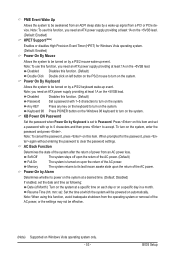
... The system stays off upon the return of the AC power, or the settings may not be effective. (Note) Supported on a specific day in a month. Memory The system returns to its last known awake state upon the return of the AC power. Note: When using this item and set a password with...
... The system stays off upon the return of the AC power, or the settings may not be effective. (Note) Supported on a specific day in a month. Memory The system returns to its last known awake state upon the return of the AC power. Note: When using this item and set a password with...

Manual
Page 65
...) for the operating system. actual size requirements vary, depending on the first SATA connector is recommended; System Requirements: • At least 512 MB of system memory • VESA compatible graphics card • Windows XP with Xpress Recovery cannot be restored using Xpress Recovery2. • USB hard drives are not supported. •...
...) for the operating system. actual size requirements vary, depending on the first SATA connector is recommended; System Requirements: • At least 512 MB of system memory • VESA compatible graphics card • Windows XP with Xpress Recovery cannot be restored using Xpress Recovery2. • USB hard drives are not supported. •...
Manual
Page 72
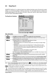
...to save the current settings to a new profile (.txt file). • Load allows you set temperature/fan speed alarm. The Memory tab provides information on the CPU temperature thresholds you to load previous settings from the buzzer or use your ATI or NVIDIA graphics...you to specify a C.I.A.2 level and a Smart Fan mode. Available functions in the notification area. Unique Features - 72 - 4-3 EasyTune 6 GIGABYTE's EasyTune 6 is a simple and easy-to-use interface that allows users to fine-tune their system-related information without the need to install ...
...to save the current settings to a new profile (.txt file). • Load allows you set temperature/fan speed alarm. The Memory tab provides information on the CPU temperature thresholds you to load previous settings from the buzzer or use your ATI or NVIDIA graphics...you to specify a C.I.A.2 level and a Smart Fan mode. Available functions in the notification area. Unique Features - 72 - 4-3 EasyTune 6 GIGABYTE's EasyTune 6 is a simple and easy-to-use interface that allows users to fine-tune their system-related information without the need to install ...


