Manual
Page 3
...product. Check your motherboard looks like this manual is protected by any form or by copyright laws and is 1.0. No part of GIGABYTE. For example, "REV: 1.0" means the revision of this manual are legally registered to use of the motherboard is the property ...information, carefully read or download the information on/from the Support&Downloads\Motherboard\Technology Guide page on your motherboard revision before updating motherboard BIOS, drivers, or when looking for technical information. Copyright © 2009 GIGA-BYTE TECHNOLOGY CO., LTD. For instructions on how to...
...product. Check your motherboard looks like this manual is protected by any form or by copyright laws and is 1.0. No part of GIGABYTE. For example, "REV: 1.0" means the revision of this manual are legally registered to use of the motherboard is the property ...information, carefully read or download the information on/from the Support&Downloads\Motherboard\Technology Guide page on your motherboard revision before updating motherboard BIOS, drivers, or when looking for technical information. Copyright © 2009 GIGA-BYTE TECHNOLOGY CO., LTD. For instructions on how to...
Manual
Page 4
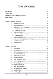
Table of Contents Box Contents...6 Optional Items...6 GA-MA785GT-UD3H Motherboard Layout 7 Block Diagram...8 Chapter 1 Hardware Installation 9 1-1 Installation Precautions 9 1-2 Product Specifications 10 1-3 Installing the CPU and CPU Cooler ...CrossFireX™ Configuration 19 1-7 Back Panel Connectors 20 1-8 Internal Connectors 23 Chapter 2 BIOS Setup 35 2-1 Startup Screen 36 2-2 The Main Menu 37 2-3 MB Intelligent Tweaker(M.I.T 39 2-4 Standard CMOS Features 45 2-5 Advanced BIOS Features 47 2-6 Integrated Peripherals 49 2-7 Power Management Setup 52 2-8 PnP/PCI Configurations ...
Table of Contents Box Contents...6 Optional Items...6 GA-MA785GT-UD3H Motherboard Layout 7 Block Diagram...8 Chapter 1 Hardware Installation 9 1-1 Installation Precautions 9 1-2 Product Specifications 10 1-3 Installing the CPU and CPU Cooler ...CrossFireX™ Configuration 19 1-7 Back Panel Connectors 20 1-8 Internal Connectors 23 Chapter 2 BIOS Setup 35 2-1 Startup Screen 36 2-2 The Main Menu 37 2-3 MB Intelligent Tweaker(M.I.T 39 2-4 Standard CMOS Features 45 2-5 Advanced BIOS Features 47 2-6 Integrated Peripherals 49 2-7 Power Management Setup 52 2-8 PnP/PCI Configurations ...
Manual
Page 5
... 62 3-3 Technical Manuals 62 3-4 Contact...63 3-5 System...63 3-6 Download Center 64 Chapter 4 Unique Features 65 4-1 Xpress Recovery2 65 4-2 BIOS Update Utilities 68 4-2-1 Updating the BIOS with the Q-Flash Utility 68 4-2-2 Updating the BIOS with the @BIOS Utility 71 4-3 EasyTune 6...72 4-4 Easy Energy Saver 73 4-5 Q-Share...75 4-6 Time Repair...76 Chapter 5 Appendix...77 5-1 Configuring SATA...
... 62 3-3 Technical Manuals 62 3-4 Contact...63 3-5 System...63 3-6 Download Center 64 Chapter 4 Unique Features 65 4-1 Xpress Recovery2 65 4-2 BIOS Update Utilities 68 4-2-1 Updating the BIOS with the Q-Flash Utility 68 4-2-2 Updating the BIOS with the @BIOS Utility 71 4-3 EasyTune 6...72 4-4 Easy Energy Saver 73 4-5 Q-Share...75 4-6 Time Repair...76 Chapter 5 Appendix...77 5-1 Configuring SATA...
Manual
Page 8
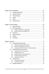
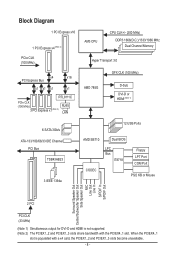
... D-Sub DVI-D or HDMI (Note 1) 6 SATA 3Gb/s ATA-133/100/66/33 IDE Channel PCI Bus TSB43AB23 3 IEEE 1394a 12 USB Ports AMD SB710 Dual BIOS CODEC LPC Bus IT8718 Floppy LPT Port COM Port PS/2 KB or Mouse Surround Speaker Out Center/Subwoofer Speaker Out Side Speaker Out MIC Line...
... D-Sub DVI-D or HDMI (Note 1) 6 SATA 3Gb/s ATA-133/100/66/33 IDE Channel PCI Bus TSB43AB23 3 IEEE 1394a 12 USB Ports AMD SB710 Dual BIOS CODEC LPC Bus IT8718 Floppy LPT Port COM Port PS/2 KB or Mouse Surround Speaker Out Center/Subwoofer Speaker Out Side Speaker Out MIC Line...
Manual
Page 12
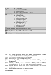
Hardware Installation - 12 - When the PCIEX4_1 slot is populated with the PCIEX4_1 slot. BIOS w w w w Unique Features w w w w w w w w w w Bundled Software w 2 x 8 Mbit flash Use of physical memory is installed, the actual memory size ... function is supported will be less than 4 GB of licensed AWARD BIOS Support for DualBIOS™ PnP 1.0a, DMI 2.0, SM BIOS 2.4, ACPI 1.0b Support for @BIOS Support for Q-Flash Support for Xpress BIOS Rescue Support for Download Center Support for Xpress Install Support for Xpress...
Hardware Installation - 12 - When the PCIEX4_1 slot is populated with the PCIEX4_1 slot. BIOS w w w w Unique Features w w w w w w w w w w Bundled Software w 2 x 8 Mbit flash Use of physical memory is installed, the actual memory size ... function is supported will be less than 4 GB of licensed AWARD BIOS Support for DualBIOS™ PnP 1.0a, DMI 2.0, SM BIOS 2.4, ACPI 1.0b Support for @BIOS Support for Q-Flash Support for Xpress BIOS Rescue Support for Download Center Support for Xpress Install Support for Xpress...
Manual
Page 16
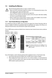
...Channel Memory Configuration This motherboard provides four DDR3 memory sockets and supports Dual Channel Technology. After the memory is installed, the BIOS will double the original memory bandwidth. Enabling Dual Channel memory mode will automatically detect the specifications and capacity of the same capacity...memory modules are divided into two channels and each channel has two memory sockets as following guidelines before installing the memory to GIGABYTE's website for optimum performance. A memory module can be installed, it is installed. 2. If you begin to be installed...
...Channel Memory Configuration This motherboard provides four DDR3 memory sockets and supports Dual Channel Technology. After the memory is installed, the BIOS will double the original memory bandwidth. Enabling Dual Channel memory mode will automatically detect the specifications and capacity of the same capacity...memory modules are divided into two channels and each channel has two memory sockets as following guidelines before installing the memory to GIGABYTE's website for optimum performance. A memory module can be installed, it is installed. 2. If you begin to be installed...
Manual
Page 18
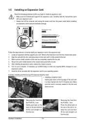
... is fully seated in the slot and does not rock. • Removing the Card from the power outlet before you begin to make any required BIOS changes for your card. Secure the card's metal bracket to release the card and then lift the card straight out from the chassis back panel... the following guidelines before installing an expansion card to prevent hardware damage. Carefully read the manual that supports your expansion card(s). 7. If necessary, go to BIOS Setup to install an expansion card: • Make sure the motherboard supports the expansion card.
... is fully seated in the slot and does not rock. • Removing the Card from the power outlet before you begin to make any required BIOS changes for your card. Secure the card's metal bracket to release the card and then lift the card straight out from the chassis back panel... the following guidelines before installing an expansion card to prevent hardware damage. Carefully read the manual that supports your expansion card(s). 7. If necessary, go to BIOS Setup to install an expansion card: • Make sure the motherboard supports the expansion card.
Manual
Page 19
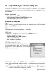
...- Set UMA Frame Buffer Size to the ATI Catalyst™ Control Center. Configuring the Graphics Driver After installing the motherboard driver in BIOS Setup, be sure to UMA. (Note 3) - Select CrossFire™ on the Graphics menu on the back panel. Set Surround View... to set the following items under the Advanced BIOS Features menu: - Hardware Installation A. An ATI Hybrid CrossFireX-supported graphics card (Note 2) B. BIOS Setup Enter BIOS Setup to Disabled. - C. System Requirements - Set Init Display First to install the...
...- Set UMA Frame Buffer Size to the ATI Catalyst™ Control Center. Configuring the Graphics Driver After installing the motherboard driver in BIOS Setup, be sure to UMA. (Note 3) - Select CrossFire™ on the Graphics menu on the back panel. Set Surround View... to set the following items under the Advanced BIOS Features menu: - Hardware Installation A. An ATI Hybrid CrossFireX-supported graphics card (Note 2) B. BIOS Setup Enter BIOS Setup to Disabled. - C. System Requirements - Set Init Display First to install the...
Manual
Page 21
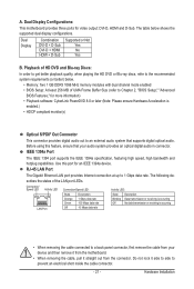
... - 21 - The table below . • Memory: Two 1 GB DDR3 1066 MHz memory modules with dual channel mode enabled • BIOS Setup: At least 256 MB of the LAN port LEDs. Playback of HD DVD and Blu-ray Discs: In order to get better playback ... feature, ensure that supports digital optical audio. Hardware Installation The following describes the states of UMA Frame Buffer Size (refer to Chapter 2, "BIOS Setup," "Advanced BIOS Features," for more information) • Playback software: CyberLink PowerDVD 8.0 or later (Note: Please ensure Hardware Acceleration is occurring • When...
... - 21 - The table below . • Memory: Two 1 GB DDR3 1066 MHz memory modules with dual channel mode enabled • BIOS Setup: At least 256 MB of the LAN port LEDs. Playback of HD DVD and Blu-ray Discs: In order to get better playback ... feature, ensure that supports digital optical audio. Hardware Installation The following describes the states of UMA Frame Buffer Size (refer to Chapter 2, "BIOS Setup," "Advanced BIOS Features," for more information) • Playback software: CyberLink PowerDVD 8.0 or later (Note: Please ensure Hardware Acceleration is occurring • When...

Manual
Page 27
... for 5 seconds.) 3. System Status LED S0 On S1 Blinking S3/S4/S5 Off 10) BATTERY The battery provides power to keep the values (such as BIOS configurations, date, and time information) in S3/S4 sleep state or powered off . Turn off your computer and unplug the power cord before replacing the...
... for 5 seconds.) 3. System Status LED S0 On S1 Blinking S3/S4/S5 Off 10) BATTERY The battery provides power to keep the values (such as BIOS configurations, date, and time information) in S3/S4 sleep state or powered off . Turn off your computer and unplug the power cord before replacing the...
Manual
Page 28
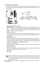
... • PW (Power Switch, Red): Connects to indicate the problem. One single short beep will be heard if no problem is detected, the BIOS may issue beeps in S1 sleep state. If a problem is detected at system startup. When connecting your system using the power switch (refer to ...Chapter 2, "BIOS Setup," "Power Management Setup," for information about beep codes. • HD (Hard Drive Activity LED, Blue) Connects to the speaker on the chassis...
... • PW (Power Switch, Red): Connects to indicate the problem. One single short beep will be heard if no problem is detected, the BIOS may issue beeps in S1 sleep state. If a problem is detected at system startup. When connecting your system using the power switch (refer to ...Chapter 2, "BIOS Setup," "Power Management Setup," for information about beep codes. • HD (Hard Drive Activity LED, Blue) Connects to the speaker on the chassis...

Manual
Page 33
...do so may cause damage to the motherboard. • After system restart, go to BIOS Setup to load factory defaults (select Load Optimized Defaults) or manually configure the BIOS settings (refer to touch the two pins for BIOS configurations). - 33 - Open: Normal Short: Clear CMOS Values • Always turn ...the CMOS values and before turning on the two pins to temporarily short the two pins or use a metal object like a screwdriver to Chapter 2, "BIOS Setup," for a few seconds. To clear the CMOS values, place a jumper cap on your computer and unplug the power cord from the jumper. ...
...do so may cause damage to the motherboard. • After system restart, go to BIOS Setup to load factory defaults (select Load Optimized Defaults) or manually configure the BIOS settings (refer to touch the two pins for BIOS configurations). - 33 - Open: Normal Short: Clear CMOS Values • Always turn ...the CMOS values and before turning on the two pins to temporarily short the two pins or use a metal object like a screwdriver to Chapter 2, "BIOS Setup," for a few seconds. To clear the CMOS values, place a jumper cap on your computer and unplug the power cord from the jumper. ...
Manual
Page 35
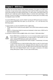
...introductions of the battery/ clearing CMOS jumper in system's failure to Chapter 5, "Troubleshooting," for how to Chapter 4, "BIOS Update Utilities." • Because BIOS flashing is potentially risky, if you do it is recommended that you need to) to keep the configuration values in the... on using the current version of BIOS, it with caution. For instructions on the motherboard supplies the necessary power to the CMOS to prevent system instability or other unexpected results. To upgrade the BIOS, use either the GIGABYTE Q-Flash or @BIOS utility. • Q-Flash allows ...
...introductions of the battery/ clearing CMOS jumper in system's failure to Chapter 5, "Troubleshooting," for how to Chapter 4, "BIOS Update Utilities." • Because BIOS flashing is potentially risky, if you do it is recommended that you need to) to keep the configuration values in the... on using the current version of BIOS, it with caution. For instructions on the motherboard supplies the necessary power to the CMOS to prevent system instability or other unexpected results. To upgrade the BIOS, use either the GIGABYTE Q-Flash or @BIOS utility. • Q-Flash allows ...
Manual
Page 36
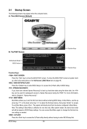
... first boot device setting as needed. : Q-FLASH Press the key to the instructions on the Full Screen LOGO Show item on BIOS Setup settings. BIOS Setup - 36 - A. Motherboard Model BIOS Version GA-MA785GT-UD3H E1 . . . . : BIOS Setup : XpressRecovery2 : Boot Menu : Qflash 06/17/2009-RS785-SB710-7A66BG04C-00 Function Keys Function Keys Function Keys: : POST SCREEN Press...
... first boot device setting as needed. : Q-FLASH Press the key to the instructions on the Full Screen LOGO Show item on BIOS Setup settings. BIOS Setup - 36 - A. Motherboard Model BIOS Version GA-MA785GT-UD3H E1 . . . . : BIOS Setup : XpressRecovery2 : Boot Menu : Qflash 06/17/2009-RS785-SB710-7A66BG04C-00 Function Keys Function Keys Function Keys: : POST SCREEN Press...
Manual
Page 37
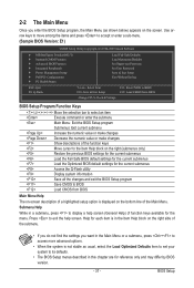
...Select Item F10: Save & Exit Setup Change CPU's Clock & Voltage F11: Save CMOS to BIOS F12: Load CMOS from BIOS BIOS Setup Program Function Keys Move the selection bar to select an item Execute command or enter the submenu... Main Menu: Exit the BIOS Setup program Submenus: Exit current submenu Increase the numeric value or make changes Decrease ...of the submenu. • If you do not find the settings you enter the BIOS Setup program, the Main Menu (as usual, select the Load Optimized Defaults item to set your system ...
...Select Item F10: Save & Exit Setup Change CPU's Clock & Voltage F11: Save CMOS to BIOS F12: Load CMOS from BIOS BIOS Setup Program Function Keys Move the selection bar to select an item Execute command or enter the submenu... Main Menu: Exit the BIOS Setup program Submenus: Exit current submenu Increase the numeric value or make changes Decrease ...of the submenu. • If you do not find the settings you enter the BIOS Setup program, the Main Menu (as usual, select the Load Optimized Defaults item to set your system ...
Manual
Page 38
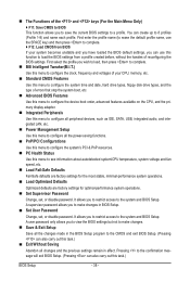
... enter the profile name (to erase the default profile name, use the SPACE key) and then press to complete. F12: Load CMOS from BIOS If your CPU, memory, etc. Standard CMOS Features Use this menu to configure the system time and date, hard drive types, floppy disk drive... types, and the type of errors that stop the system boot, etc. Advanced BIOS Features Use this menu to configure the device boot order, advanced features available on the CPU, and the primary display adapter. Integrated Peripherals Use...
... enter the profile name (to erase the default profile name, use the SPACE key) and then press to complete. F12: Load CMOS from BIOS If your CPU, memory, etc. Standard CMOS Features Use this menu to configure the system time and date, hard drive types, floppy disk drive... types, and the type of errors that stop the system boot, etc. Advanced BIOS Features Use this menu to configure the device boot order, advanced features available on the CPU, and the primary display adapter. Integrated Peripherals Use...
Manual
Page 39
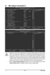
... system voltage settings. - 39 - Incorrectly doing overclock/overvoltage may result in damage to CPU, chipset, or memory and reduce the useful life of these components. BIOS Setup 2-3 MB Intelligent Tweaker(M.I.T.) CMOS Setup Utility-Copyright (C) 1984-2009 Award Software MB Intelligent Tweaker(M.I .T.) CPU Voltage Control Normal CPU Vcore [Normal] 1.3250V Item Help...
... system voltage settings. - 39 - Incorrectly doing overclock/overvoltage may result in damage to CPU, chipset, or memory and reduce the useful life of these components. BIOS Setup 2-3 MB Intelligent Tweaker(M.I.T.) CMOS Setup Utility-Copyright (C) 1984-2009 Award Software MB Intelligent Tweaker(M.I .T.) CPU Voltage Control Normal CPU Vcore [Normal] 1.3250V Item Help...

Manual
Page 40
... configure the settings to select the EC firmware version when Advanced Clock Calibration is enabled. A message which says "BIOS Is Updating EC Firmware!!! Value (All Cores) This option is configurable only when Advanced Clock Calibration is set to All Cores. ...Core 0), Value (Core 1), Value (Core 2), Value (Core 3) This option is configurable only when Advanced Clock Calibration is set to All Cores. BIOS Setup - 40 - All Cores Configures Advanced Clock Calibration for each CPU core. Advanced Clock Calibration CMOS Setup Utility-Copyright (C) 1984-2009 Award Software ...
... configure the settings to select the EC firmware version when Advanced Clock Calibration is enabled. A message which says "BIOS Is Updating EC Firmware!!! Value (All Cores) This option is configurable only when Advanced Clock Calibration is set to All Cores. ...Core 0), Value (Core 1), Value (Core 2), Value (Core 3) This option is configurable only when Advanced Clock Calibration is set to All Cores. BIOS Setup - 40 - All Cores Configures Advanced Clock Calibration for each CPU core. Advanced Clock Calibration CMOS Setup Utility-Copyright (C) 1984-2009 Award Software ...
Manual
Page 41
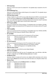
... Clock to 16 bit. X8.00 Sets Memory Clock to x1~x10 (200 MHz~2.0 GHz). Important It is dependent on the CPU being used . Auto BIOS will automatically adjust the HT Link Width. (Default) 8 bit Sets HT Link Width to 8 bit. 16 bit Sets HT Link Width to X4.00... The adjustable range is highly recommended that the CPU frequency be set the memory clock as required. Auto (default) allows the BIOS to X6.66. Set Memory Clock Determines whether to manually set the memory clock. X6.66 Sets Memory Clock to automatically adjust the CPU host ...
... Clock to 16 bit. X8.00 Sets Memory Clock to x1~x10 (200 MHz~2.0 GHz). Important It is dependent on the CPU being used . Auto BIOS will automatically adjust the HT Link Width. (Default) 8 bit Sets HT Link Width to 8 bit. 16 bit Sets HT Link Width to X4.00... The adjustable range is highly recommended that the CPU frequency be set the memory clock as required. Auto (default) allows the BIOS to X6.66. Set Memory Clock Determines whether to manually set the memory clock. X6.66 Sets Memory Clock to automatically adjust the CPU host ...
Manual
Page 42
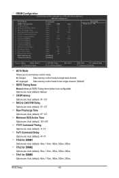
...-channel. (Default) DDR3 Timing Items Manual allows all DDR3 Timing items below to set memory control mode. TwTr Command Delay Options are : Auto (default), Manual. BIOS Setup - 42 - CAS# latency Options are : Auto (default), 5T~12T. Auto 10T Auto 5T Auto 28T Auto 4T [Enabled] [Enabled] Auto 7T 7T 7T 30T...
...-channel. (Default) DDR3 Timing Items Manual allows all DDR3 Timing items below to set memory control mode. TwTr Command Delay Options are : Auto (default), Manual. BIOS Setup - 42 - CAS# latency Options are : Auto (default), 5T~12T. Auto 10T Auto 5T Auto 28T Auto 4T [Enabled] [Enabled] Auto 7T 7T 7T 30T...


