Manual
Page 3
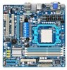
... is the property of this manual may be made by GIGABYTE without GIGABYTE's prior written permission. The trademarks mentioned in this manual are legally registered to use of the product, read the Quick Installation Guide included with the product. Disclaimer Information in this manual... is protected by any form or by copyright laws and is 1.0. For instructions on how to their respective owners. No part of GIGABYTE. Copyright © 2009 GIGA-...
... is the property of this manual may be made by GIGABYTE without GIGABYTE's prior written permission. The trademarks mentioned in this manual are legally registered to use of the product, read the Quick Installation Guide included with the product. Disclaimer Information in this manual... is protected by any form or by copyright laws and is 1.0. For instructions on how to their respective owners. No part of GIGABYTE. Copyright © 2009 GIGA-...
Manual
Page 4
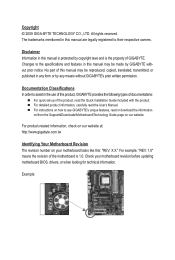
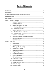
Table of Contents Box Contents...6 Optional Items...6 GA-MA785GPMT-UD2H/GA-MA785GMT-UD2H(US2H 7 Motherboard Layout...7 Block Diagram...8 Chapter 1 Hardware Installation 9 1-1 Installation Precautions 9 1-2 Product Specifications 10 1-3 Installing the CPU and CPU Cooler 13 1-3-1 Installing the CPU 13 1-3-2 Installing the CPU Cooler 15 1-4 Installing the Memory 16 1-4-1 Dual Channel Memory Configuration 16 1-4-2 Installing a Memory 17 1-5 Installing an Expansion Card 18 1-6 Setup of the ATI Hybrid...
Table of Contents Box Contents...6 Optional Items...6 GA-MA785GPMT-UD2H/GA-MA785GMT-UD2H(US2H 7 Motherboard Layout...7 Block Diagram...8 Chapter 1 Hardware Installation 9 1-1 Installation Precautions 9 1-2 Product Specifications 10 1-3 Installing the CPU and CPU Cooler 13 1-3-1 Installing the CPU 13 1-3-2 Installing the CPU Cooler 15 1-4 Installing the Memory 16 1-4-1 Dual Channel Memory Configuration 16 1-4-2 Installing a Memory 17 1-5 Installing an Expansion Card 18 1-6 Setup of the ATI Hybrid...
Manual
Page 5
...Repair...76 Chapter 5 Appendix...77 5-1 Configuring SATA Hard Drive(s 77 5-1-1 Configuring the Onboard SATA Controller 77 5-1-2 Making a SATA RAID/AHCI Driver Diskette 83 5-1-3 Installing the SATA RAID/AHCI Driver and Operating System 84 5-2 Configuring Audio Input and Output 88 5-2-1 Configuring 2/4/5.1/7.1-Channel Audio 88 5-2-2 Configuring S/PDIF In/Out 90 5-2-3... Microphone Recording 93 5-2-5 Using the Sound Recorder 95 5-3 Troubleshooting 96 5-3-1 Frequently Asked Questions 96 5-3-2 Troubleshooting Procedure 97 5-4 Regulatory Statements 99 j Only for GA-MA785GMT-UD2H. - 5 -
...Repair...76 Chapter 5 Appendix...77 5-1 Configuring SATA Hard Drive(s 77 5-1-1 Configuring the Onboard SATA Controller 77 5-1-2 Making a SATA RAID/AHCI Driver Diskette 83 5-1-3 Installing the SATA RAID/AHCI Driver and Operating System 84 5-2 Configuring Audio Input and Output 88 5-2-1 Configuring 2/4/5.1/7.1-Channel Audio 88 5-2-2 Configuring S/PDIF In/Out 90 5-2-3... Microphone Recording 93 5-2-5 Using the Sound Recorder 95 5-3 Troubleshooting 96 5-3-1 Frequently Asked Questions 96 5-3-2 Troubleshooting Procedure 97 5-4 Regulatory Statements 99 j Only for GA-MA785GMT-UD2H. - 5 -
Manual
Page 6
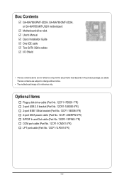
... (Part No. 12CR1-1SPINO-1*R) COM port cable (Part No. 12CF1-1CM001-3*R) LPT port cable (Part No. 12CF1-1LP001-0*R) - 6 - Box Contents GA-MA785GPMT-UD2H, GA-MA785GMT-UD2H, or GA-MA785GMT-US2H motherboard Motherboard driver disk User's Manual Quick Installation Guide One IDE cable Two SATA 3Gb/s cables I/O Shield • The box contents above are subject to change without notice...
... (Part No. 12CR1-1SPINO-1*R) COM port cable (Part No. 12CF1-1CM001-3*R) LPT port cable (Part No. 12CF1-1LP001-0*R) - 6 - Box Contents GA-MA785GPMT-UD2H, GA-MA785GMT-UD2H, or GA-MA785GMT-US2H motherboard Motherboard driver disk User's Manual Quick Installation Guide One IDE cable Two SATA 3Gb/s cables I/O Shield • The box contents above are subject to change without notice...

Manual
Page 9
...as a motherboard, CPU or memory. If you are connected tightly and securely. • When handling the motherboard, avoid touching any installation steps or have it on top of an antistatic pad or within an electrostatic shielding container. • Before unplugging the power supply ...cable from the power outlet before installing or removing the motherboard or other hardware components. • When connecting hardware components to the internal connectors on the motherboard, make...
...as a motherboard, CPU or memory. If you are connected tightly and securely. • When handling the motherboard, avoid touching any installation steps or have it on top of an antistatic pad or within an electrostatic shielding container. • Before unplugging the power supply ...cable from the power outlet before installing or removing the motherboard or other hardware components. • When connecting hardware components to the internal connectors on the motherboard, make...
Manual
Page 10
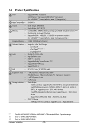
...drive "*" j k The GA-MA785GPMT-UD2H/GA-MA785GMT-UD2H adopts All-Solid Capacitor design. Hardware Installation - 10 - Support for GA-MA785GMT-UD2H. 1-2 Product Specifications CPU Support for AM3 processors: AMD Phenom™ II processor/ AMD Athlon™ II processor (Go to GIGABYTE's website for the latest ... Realtek ALC889A codec High Definition Audio 2/4/5.1/7.1-channel Support for Dolby® Home Theater jk Support for S/PDIF In/Out Support for GA-MA785GPMT-UD2H. Only for CD In LAN RTL8111C chip (10/100/1000 Mbit) Expansion Slots 1 x PCI Express ...
...drive "*" j k The GA-MA785GPMT-UD2H/GA-MA785GMT-UD2H adopts All-Solid Capacitor design. Hardware Installation - 10 - Support for GA-MA785GMT-UD2H. 1-2 Product Specifications CPU Support for AM3 processors: AMD Phenom™ II processor/ AMD Athlon™ II processor (Go to GIGABYTE's website for the latest ... Realtek ALC889A codec High Definition Audio 2/4/5.1/7.1-channel Support for Dolby® Home Theater jk Support for S/PDIF In/Out Support for GA-MA785GPMT-UD2H. Only for CD In LAN RTL8111C chip (10/100/1000 Mbit) Expansion Slots 1 x PCI Express ...

Manual
Page 11
... CPU overheating warning CPU/System/Power fan fail warning CPU/System fan speed control (Note 4) - 11 - USB IEEE 1394 Internal w Connectors w w w w w w w w w w w w w w w w w w Back Panel w Connectors w w w w w w w w w I . Hardware Installation
... CPU overheating warning CPU/System/Power fan fail warning CPU/System fan speed control (Note 4) - 11 - USB IEEE 1394 Internal w Connectors w w w w w w w w w w w w w w w w w w Back Panel w Connectors w w w w w w w w w I . Hardware Installation
Manual
Page 12
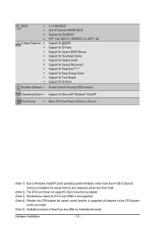
...DMI 2.0, SM BIOS 2.4, ACPI 1.0b Support for @BIOS Support for Q-Flash Support for Xpress BIOS Rescue Support for Download Center Support for Xpress Install Support for Xpress Recovery2 Support for EasyTune (Note 5) Support for Easy Energy Saver Support for Time Repair Support for Q-Share Norton Internet Security (OEM ...Factor; 24.3cm x 24.3cm (Note 1) Due to Windows Vista/XP 32-bit operating system limitation, when more than 4 GB of physical memory is installed, the actual memory size displayed will be less than 4 GB. (Note 2) The DVI-D port does not support D-Sub connection by adapter. (Note ...
...DMI 2.0, SM BIOS 2.4, ACPI 1.0b Support for @BIOS Support for Q-Flash Support for Xpress BIOS Rescue Support for Download Center Support for Xpress Install Support for Xpress Recovery2 Support for EasyTune (Note 5) Support for Easy Energy Saver Support for Time Repair Support for Q-Share Norton Internet Security (OEM ...Factor; 24.3cm x 24.3cm (Note 1) Due to Windows Vista/XP 32-bit operating system limitation, when more than 4 GB of physical memory is installed, the actual memory size displayed will be less than 4 GB. (Note 2) The DVI-D port does not support D-Sub connection by adapter. (Note ...

Manual
Page 13
... surface of the CPU. • Do not turn off the computer and unplug the power cord from the power outlet before you begin to install the CPU: • Make sure that the system bus frequency be inserted if oriented incorrectly. (Or you wish to set beyond the standard ...8226; Always turn on the computer if the CPU cooler is not recommended that the motherboard supports the CPU. (Go to GIGABYTE's website for the peripherals. It is not installed, otherwise overheating and dam- Locate the pin one of the Socket AM3 Socket A Small Triangle Marking Denotes CPU Pin One AM3...
... surface of the CPU. • Do not turn off the computer and unplug the power cord from the power outlet before you begin to install the CPU: • Make sure that the system bus frequency be inserted if oriented incorrectly. (Or you wish to set beyond the standard ...8226; Always turn on the computer if the CPU cooler is not recommended that the motherboard supports the CPU. (Go to GIGABYTE's website for the peripherals. It is not installed, otherwise overheating and dam- Locate the pin one of the Socket AM3 Socket A Small Triangle Marking Denotes CPU Pin One AM3...

Manual
Page 14
... finger down on the CPU socket and gently insert the CPU into the fully locked position. Hardware Installation - 14 - Follow the steps below to correctly install the CPU into the motherboard CPU socket. • Before installing the CPU, make sure to turn off the computer and unplug the power cord from the power...
... finger down on the CPU socket and gently insert the CPU into the fully locked position. Hardware Installation - 14 - Follow the steps below to correctly install the CPU into the motherboard CPU socket. • Before installing the CPU, make sure to turn off the computer and unplug the power cord from the power...

Manual
Page 15
...the CPU cooler clip to hook it to the mounting lug on the CPU. 1-3-2 Installing the CPU Cooler Follow the steps below to correctly install the CPU cooler on the CPU. (The following procedure uses the GIGABYTE cooler as the picture above shows) to lock into place. (Refer to your ...CPU cooler installation manual for instructions on installing the cooler.) Step 5: Finally, attach the power connector of...
...the CPU cooler clip to hook it to the mounting lug on the CPU. 1-3-2 Installing the CPU Cooler Follow the steps below to correctly install the CPU cooler on the CPU. (The following procedure uses the GIGABYTE cooler as the picture above shows) to lock into place. (Refer to your ...CPU cooler installation manual for instructions on installing the cooler.) Step 5: Finally, attach the power connector of...
Manual
Page 16
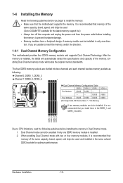
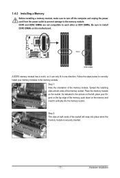
... DDR3_4 Due to install the memory: • Make sure that memory of the memory. Dual Channel mode cannot be installed in the same ...installing the memory in Dual Channel mode. 1. Hardware Installation - 16 - If you install them in the DDR3_1 and DDR3_2 sockets. After the memory is installed...installed, it is recommended that memory of the same capacity, brand, speed, and chips be used and installed in only one DDR3 memory module is installed...each channel has two memory sockets as following guidelines before installing the memory to prevent hardware damage. • Memory ...
... DDR3_4 Due to install the memory: • Make sure that memory of the memory. Dual Channel mode cannot be installed in the same ...installing the memory in Dual Channel mode. 1. Hardware Installation - 16 - If you install them in the DDR3_1 and DDR3_2 sockets. After the memory is installed...installed, it is recommended that memory of the same capacity, brand, speed, and chips be used and installed in only one DDR3 memory module is installed...each channel has two memory sockets as following guidelines before installing the memory to prevent hardware damage. • Memory ...
Manual
Page 17
Place the memory module on this motherboard. DDR3 and DDR2 DIMMs are not compatible to each other or DDR DIMMs. Be sure to install DDR3 DIMMs on the socket. Step 1: Note the orientation of the socket will snap into the memory socket. As indicated in the picture on...place your memory modules in one direction. Step 2: The clips at both ends of the memory module. Follow the steps below to the memory module. 1-4-2 Installing a Memory Before installing a memory module, make sure to turn off the computer and unplug the power cord from the power outlet to prevent damage to correctly...
Place the memory module on this motherboard. DDR3 and DDR2 DIMMs are not compatible to each other or DDR DIMMs. Be sure to install DDR3 DIMMs on the socket. Step 1: Note the orientation of the socket will snap into the memory socket. As indicated in the picture on...place your memory modules in one direction. Step 2: The clips at both ends of the memory module. Follow the steps below to the memory module. 1-4-2 Installing a Memory Before installing a memory module, make sure to turn off the computer and unplug the power cord from the power outlet to prevent damage to correctly...
Manual
Page 18
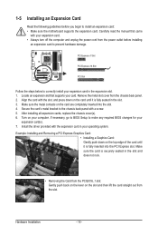
... supports your expansion card. • Always turn off the computer and unplug the power cord from the power outlet before you begin to install an expansion card: • Make sure the motherboard supports the expansion card. Align the card with your card. Secure the card's metal... on the slot and then lift the card straight out from the chassis back panel. 2. Install the driver provided with a screw. 5. 1-5 Installing an Expansion Card Read the following guidelines before installing an expansion card to prevent hardware damage. PCI Express x1 Slot PCI Express x16 Slot PCI ...
... supports your expansion card. • Always turn off the computer and unplug the power cord from the power outlet before you begin to install an expansion card: • Make sure the motherboard supports the expansion card. Align the card with your card. Secure the card's metal... on the slot and then lift the card straight out from the chassis back panel. 2. Install the driver provided with a screw. 5. 1-5 Installing an Expansion Card Read the following guidelines before installing an expansion card to prevent hardware damage. PCI Express x1 Slot PCI Express x16 Slot PCI ...
Manual
Page 19
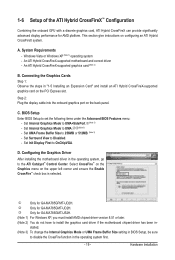
... UMA+SidePort.j(Note 3) - BIOS Setup Enter BIOS Setup to install the graphics card driver if the motherboard chipset driver has been in the operating system first. - 19 - j Only for GA-MA785GMT-UD2H. System Requirements - Step 2: Plug the display cable into the... onboard graphics port on configuring an ATI Hybrid CrossFireX system. k Only for GA-MA785GPMT-UD2H. Hardware Installation A. C. 1-6 Setup of the ATI Hybrid CrossFireX™...
... UMA+SidePort.j(Note 3) - BIOS Setup Enter BIOS Setup to install the graphics card driver if the motherboard chipset driver has been in the operating system first. - 19 - j Only for GA-MA785GMT-UD2H. System Requirements - Step 2: Plug the display cable into the... onboard graphics port on configuring an ATI Hybrid CrossFireX system. k Only for GA-MA785GPMT-UD2H. Hardware Installation A. C. 1-6 Setup of the ATI Hybrid CrossFireX™...

Manual
Page 20
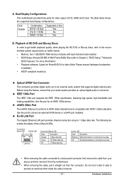
... and 2-channel-LPCM formats. (AC3 and DTS require the use of 1920x1080p but the actual resolutions supported depend on the monitor being used. • After installing the HDMI device, make sure the default device for USB devices such as a USB keyboard/mouse, USB printer, USB flash drive and etc. HDMI Port... or PS/2 Mouse Port Use this port. Connect a monitor that supports D-Sub connection to transmit the uncompressed audio/video signals and is HDCP compliant. Hardware Installation - 20 -
... and 2-channel-LPCM formats. (AC3 and DTS require the use of 1920x1080p but the actual resolutions supported depend on the monitor being used. • After installing the HDMI device, make sure the default device for USB devices such as a USB keyboard/mouse, USB printer, USB flash drive and etc. HDMI Port... or PS/2 Mouse Port Use this port. Connect a monitor that supports D-Sub connection to transmit the uncompressed audio/video signals and is HDCP compliant. Hardware Installation - 20 -
Manual
Page 21
... this feature, ensure that supports digital optical audio. Use the port to 1 Gbps data rate. Do not rock it straight out from the connector. Hardware Installation The table below . • Memory: Two 1 GB DDR3 1066 memory modules with SATA 1.5Gb/s standard. Dual Display Combination DVI-D + D-Sub DVI-D + HDMI HDMI + D-Sub Supported...
... this feature, ensure that supports digital optical audio. Use the port to 1 Gbps data rate. Do not rock it straight out from the connector. Hardware Installation The table below . • Memory: Two 1 GB DDR3 1066 memory modules with SATA 1.5Gb/s standard. Dual Display Combination DVI-D + D-Sub DVI-D + HDMI HDMI + D-Sub Supported...
Manual
Page 22
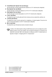
Use this audio jack for GA-MA785GMT-US2H. j Only for line in devices such as an optical drive, walkman, etc. Hardware Installation - 22 - In addition to the default speakers settings, the ~ audio jacks can be connected to the instructions on setting up a 2/4/5.1/7.1-channel audio ... audio configuration. Rear Speaker Out Jack (Black) Use this audio jack to connect center/subwoofer speakers in a 5.1/7.1-channel audio configuration. k Only for GA-MA785GMT-UD2H. Mic In Jack (Pink) The default Mic in jack. Line Out Jack (Green) The default line out jack.
Use this audio jack for GA-MA785GMT-US2H. j Only for line in devices such as an optical drive, walkman, etc. Hardware Installation - 22 - In addition to the default speakers settings, the ~ audio jacks can be connected to the instructions on setting up a 2/4/5.1/7.1-channel audio ... audio configuration. Rear Speaker Out Jack (Black) Use this audio jack to connect center/subwoofer speakers in a 5.1/7.1-channel audio configuration. k Only for GA-MA785GMT-UD2H. Mic In Jack (Pink) The default Mic in jack. Line Out Jack (Green) The default line out jack.

Manual
Page 23
Unplug the power cord from the power outlet to prevent damage to the devices. • After installing the device and before connecting external devices: • First make sure the device cable has been securely attached to turn off the devices and your ...) BATTERY Read the following guidelines before turning on the computer, make sure your devices are compliant with the connectors you wish to connect. • Before installing the devices, be sure to the connector on the motherboard. - 23 - Hardware...
Unplug the power cord from the power outlet to prevent damage to the devices. • After installing the device and before connecting external devices: • First make sure the device cable has been securely attached to turn off the devices and your ...) BATTERY Read the following guidelines before turning on the computer, make sure your devices are compliant with the connectors you wish to connect. • Before installing the devices, be sure to the connector on the motherboard. - 23 - Hardware...

Manual
Page 24
... a power supply that does not provide the required power, the result can lead to an unstable or unbootable system. • The power connectors are properly installed. Definition 1 GND (Only for 2x4-pin 12V) 2 GND (Only for 2x4-pin 12V) 3 GND 4 GND 5 +12V (Only for 2x4-pin 12V) 6 +12V (Only ...12V GND PS_ON (soft On/Off) GND GND GND -5V +5V +5V +5V (Only for 2x12-pin ATX) GND (Only for 2x12-pin ATX) Hardware Installation - 24 - The power connector possesses a foolproof design. 1/2) ATX_12V_2X4/ATX (2x4 12V Power Connector and 2x12 Main Power Connector) With the use of the power connector...
... a power supply that does not provide the required power, the result can lead to an unstable or unbootable system. • The power connectors are properly installed. Definition 1 GND (Only for 2x4-pin 12V) 2 GND (Only for 2x4-pin 12V) 3 GND 4 GND 5 +12V (Only for 2x4-pin 12V) 6 +12V (Only ...12V GND PS_ON (soft On/Off) GND GND GND -5V +5V +5V +5V (Only for 2x12-pin ATX) GND (Only for 2x12-pin ATX) Hardware Installation - 24 - The power connector possesses a foolproof design. 1/2) ATX_12V_2X4/ATX (2x4 12V Power Connector and 2x12 Main Power Connector) With the use of the power connector...


