Manual
Page 3
...-related information, check on our website at: http://www.gigabyte.com.tw Identifying Your Motherboard Revision The revision number on... Documentation Classifications In order to assist in any form or by GIGABYTE without GIGABYTE's prior written permission. No part of this manual may be... - 3 - Check your motherboard looks like this product, GIGABYTE provides the following types of GIGABYTE. Copyright © 2009 GIGA-BYTE TECHNOLOGY CO., LTD. For...61550; For instructions on how to use GIGABYTE's unique features, read or download the information on/from the Support...
...-related information, check on our website at: http://www.gigabyte.com.tw Identifying Your Motherboard Revision The revision number on... Documentation Classifications In order to assist in any form or by GIGABYTE without GIGABYTE's prior written permission. No part of this manual may be... - 3 - Check your motherboard looks like this product, GIGABYTE provides the following types of GIGABYTE. Copyright © 2009 GIGA-BYTE TECHNOLOGY CO., LTD. For...61550; For instructions on how to use GIGABYTE's unique features, read or download the information on/from the Support...

Manual
Page 4
Table of Contents Box Contents ...6 OptionalItems ...6 GA-M85M-US2H Motherboard Layout 7 Block Diagram ...8 Chapter 1 Hardware Installation 9 1-1 Installation Precautions 9 1-2 Product Specifications 10 1-3 Installing the CPU and CPU Cooler 13...NVIDIA Hybrid SLI Function 19 1-7 Back Panel Connectors 20 1-8 Internal Connectors 23 Chapter 2 BIOS Setup 33 2-1 Startup Screen 34 2-2 The Main Menu 35 2-3 MB Intelligent Tweaker(M.I.T 37 2-4 Standard CMOS Features 40 2-5 Advanced BIOS Features 42 2-6 IntegratedPeripherals 45 2-7 Power Management Setup 48 2-8 PnP/PCI Configurations 50 ...
Table of Contents Box Contents ...6 OptionalItems ...6 GA-M85M-US2H Motherboard Layout 7 Block Diagram ...8 Chapter 1 Hardware Installation 9 1-1 Installation Precautions 9 1-2 Product Specifications 10 1-3 Installing the CPU and CPU Cooler 13...NVIDIA Hybrid SLI Function 19 1-7 Back Panel Connectors 20 1-8 Internal Connectors 23 Chapter 2 BIOS Setup 33 2-1 Startup Screen 34 2-2 The Main Menu 35 2-3 MB Intelligent Tweaker(M.I.T 37 2-4 Standard CMOS Features 40 2-5 Advanced BIOS Features 42 2-6 IntegratedPeripherals 45 2-7 Power Management Setup 48 2-8 PnP/PCI Configurations 50 ...
Manual
Page 5
... 58 3-3 Driver CD Information 58 3-4 Hardware Information 59 3-5 Contact Us ...59 Chapter 4 Unique Features 61 4-1 Xpress Recovery2 61 4-2 BIOS Update Utilities 64 4-2-1 Updating the BIOS with the Q-Flash Utility 64 4-2-2 Updating the BIOS with the @BIOS Utility 67 4-3 EasyTune 6 ...68 4-4 Easy Energy Saver 69 Chapter 5 Appendix ...71 5-1 Configuring SATA Hard Drive(s 71 5-1-1 Configuring the...
... 58 3-3 Driver CD Information 58 3-4 Hardware Information 59 3-5 Contact Us ...59 Chapter 4 Unique Features 61 4-1 Xpress Recovery2 61 4-2 BIOS Update Utilities 64 4-2-1 Updating the BIOS with the Q-Flash Utility 64 4-2-2 Updating the BIOS with the @BIOS Utility 67 4-3 EasyTune 6 ...68 4-4 Easy Energy Saver 69 Chapter 5 Appendix ...71 5-1 Configuring SATA Hard Drive(s 71 5-1-1 Configuring the...
Manual
Page 8
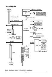
... DVI-D or HDMI (Note) NVIDIA® GeForce 8100 10 USB Ports 6 SATA 3Gb/s ATA-133/100/66/33 IDE Channel CODEC LPC BUS IT8718 Dual BIOS Floppy LPT Port COM Port PS/2 KB or Mouse Surround Speaker Out Center/Subwoofer Speaker Out Side Speaker Out MIC Line-Out Line-In SPDIF...
... DVI-D or HDMI (Note) NVIDIA® GeForce 8100 10 USB Ports 6 SATA 3Gb/s ATA-133/100/66/33 IDE Channel CODEC LPC BUS IT8718 Dual BIOS Floppy LPT Port COM Port PS/2 KB or Mouse Surround Speaker Out Center/Subwoofer Speaker Out Side Speaker Out MIC Line-Out Line-In SPDIF...

Manual
Page 11
... temperature detection CPU/System fan speed detection CPU/System overheating warning CPU/System fan fail warning CPU fan speed control (Note 7) BIOS 2 x 8 Mbit flash Use of licensed AWARD BIOS Support for DualBIOSTM PnP 1.0a, DMI 2.0, SM...
... temperature detection CPU/System fan speed detection CPU/System overheating warning CPU/System fan fail warning CPU fan speed control (Note 7) BIOS 2 x 8 Mbit flash Use of licensed AWARD BIOS Support for DualBIOSTM PnP 1.0a, DMI 2.0, SM...

Manual
Page 12
GA-M85M-US2H Motherboard - 12 - Unique Features Bundled Software Operating System Form Factor Support for @BIOS Support for Q-Flash Support for Virtual Dual BIOS Support for Download Center Support for Xpress Install Support for Xpress Recovery2 Support for EasyTune (Note 8) Support for Easy Energy ...
GA-M85M-US2H Motherboard - 12 - Unique Features Bundled Software Operating System Form Factor Support for @BIOS Support for Q-Flash Support for Virtual Dual BIOS Support for Download Center Support for Xpress Install Support for Xpress Recovery2 Support for EasyTune (Note 8) Support for Easy Energy ...

Manual
Page 16
... before installing the memory in only one DDR2 memory module is installed, the BIOS will double the original memory bandwidth. Dual Channel mode cannot be used . A memory module can be used . (Go to GIGABYTE's website for the latest memory support list.) • Always turn off the... only one direction. It is recommended that memory of the same capacity, brand, speed, and chips be installed in Dual Channel mode. 1. GA-M85M-US2H Motherboard - 16 - The two DDR2 memory sockets are divided into two channels as following guidelines before you are unable to install the memory: ...
... before installing the memory in only one DDR2 memory module is installed, the BIOS will double the original memory bandwidth. Dual Channel mode cannot be used . A memory module can be used . (Go to GIGABYTE's website for the latest memory support list.) • Always turn off the... only one direction. It is recommended that memory of the same capacity, brand, speed, and chips be installed in Dual Channel mode. 1. GA-M85M-US2H Motherboard - 16 - The two DDR2 memory sockets are divided into two channels as following guidelines before you are unable to install the memory: ...

Manual
Page 18
... expansion slot. 1. If necessary, go to BIOS Setup to make any required BIOS changes for your expansion card in the slot and does not rock. • Removing the Card: Gently push back on the lever on the card are completely inserted into the PCI Express x16 slot. GA-M85M-US2H Motherboard - 18 - Carefully read the...
... expansion slot. 1. If necessary, go to BIOS Setup to make any required BIOS changes for your expansion card in the slot and does not rock. • Removing the Card: Gently push back on the lever on the card are completely inserted into the PCI Express x16 slot. GA-M85M-US2H Motherboard - 18 - Carefully read the...
Manual
Page 19
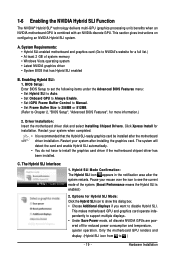
...have to see the current mode of system memory • Windows Vista operating system • Latest NVIDIA graphics driver • System BIOS that the Hybrid SLI-ready graphics card be installed after the motherboard driver installation. Enabling Hybrid SLI: 1. Restart your mouse over the...• Set iGPU Frame Buffer Control to Manual. • Set Frame Buffer Size to 256MB or 512MB. (Refer to Chapter 2, "BIOS Setup", "Advanced BIOS Features", for installation. The Hybrid SLI Interface: 1. 1-6 Enabling the NVIDIA Hybrid SLI Function The NVIDIA® Hybrid SLI® technology ...
...have to see the current mode of system memory • Windows Vista operating system • Latest NVIDIA graphics driver • System BIOS that the Hybrid SLI-ready graphics card be installed after the motherboard driver installation. Enabling Hybrid SLI: 1. Restart your mouse over the...• Set iGPU Frame Buffer Control to Manual. • Set Frame Buffer Size to 256MB or 512MB. (Refer to Chapter 2, "BIOS Setup", "Advanced BIOS Features", for installation. The Hybrid SLI Interface: 1. 1-6 Enabling the NVIDIA Hybrid SLI Function The NVIDIA® Hybrid SLI® technology ...

Manual
Page 21
...more information) • Playback software: CyberLink PowerDVD 8.0 or above processor • Memory: Two 1 GB DDR2 800 memory modules with dual channel mode enabled • BIOS Setup: At least 256 MB of the LAN port LEDs. Playback of HD DVD and Blu-ray Discs: In order to get better playback quality..., when playing the HD DVD or Blu-ray discs, refer to Chapter 2, "BIOS Setup," "Advanced BIOS Features," for video output: DVI-D, HDMI and D-Sub. RJ-45 LAN Port The Gigabit Ethernet LAN port provides Internet connection at up to this...
...more information) • Playback software: CyberLink PowerDVD 8.0 or above processor • Memory: Two 1 GB DDR2 800 memory modules with dual channel mode enabled • BIOS Setup: At least 256 MB of the LAN port LEDs. Playback of HD DVD and Blu-ray Discs: In order to get better playback quality..., when playing the HD DVD or Blu-ray discs, refer to Chapter 2, "BIOS Setup," "Advanced BIOS Features," for video output: DVI-D, HDMI and D-Sub. RJ-45 LAN Port The Gigabit Ethernet LAN port provides Internet connection at up to this...

Manual
Page 27
... off your computer and unplug the power cord. 2. Replace the battery. 4. Replace the battery when the battery voltage drops to keep the values (such as BIOS configurations, date, and time information) in accordance with an incorrect model. • Contact the place of explosion if the battery is in S1 sleep state...
... off your computer and unplug the power cord. 2. Replace the battery. 4. Replace the battery when the battery voltage drops to keep the values (such as BIOS configurations, date, and time information) in accordance with an incorrect model. • Contact the place of explosion if the battery is in S1 sleep state...
Manual
Page 28
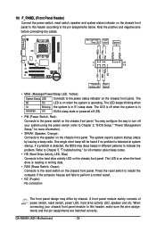
... RESRES+ NC Hard Drive Activity LED Reset Switch • MSG (Message/Power/Sleep LED, Yellow): System Status LED Connects to the pin assignments below. GA-M85M-US2H Motherboard - 28 - You may configure the way to turn off (S5). • PW (Power Switch, Red): Connects to perform a normal restart... switch, power LED, hard drive activity LED, speaker and etc. When connecting your system using the power switch (refer to Chapter 2, "BIOS Setup," "Power Management Setup," for information about beep codes. • HD (Hard Drive Activity LED, Blue) Connects to this header according...
... RESRES+ NC Hard Drive Activity LED Reset Switch • MSG (Message/Power/Sleep LED, Yellow): System Status LED Connects to the pin assignments below. GA-M85M-US2H Motherboard - 28 - You may configure the way to turn off (S5). • PW (Power Switch, Red): Connects to perform a normal restart... switch, power LED, hard drive activity LED, speaker and etc. When connecting your system using the power switch (refer to Chapter 2, "BIOS Setup," "Power Management Setup," for information about beep codes. • HD (Hard Drive Activity LED, Blue) Connects to this header according...
Manual
Page 31
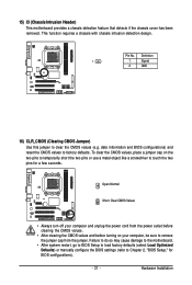
...the CMOS values, place a jumper cap on your computer and unplug the power cord from the jumper. Pin No. date information and BIOS configurations) and reset the CMOS values to remove the jumper cap from the power outlet before clearing the CMOS values. • After ... so may cause damage to the motherboard. • After system restart, go to BIOS Setup to load factory defaults (select Load Optimized Defaults) or manually configure the BIOS settings (refer to Chapter 2, "BIOS Setup," for a few seconds. This function requires a chassis with chassis intrusion detection design...
...the CMOS values, place a jumper cap on your computer and unplug the power cord from the jumper. Pin No. date information and BIOS configurations) and reset the CMOS values to remove the jumper cap from the power outlet before clearing the CMOS values. • After ... so may cause damage to the motherboard. • After system restart, go to BIOS Setup to load factory defaults (select Load Optimized Defaults) or manually configure the BIOS settings (refer to Chapter 2, "BIOS Setup," for a few seconds. This function requires a chassis with chassis intrusion detection design...
Manual
Page 33
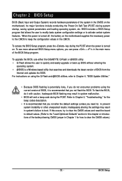
... the user to modify basic system configuration settings or to quickly and easily upgrade or back up BIOS without entering the operating system. • @BIOS is turned on the motherboard. To upgrade the BIOS, use either the GIGABYTE Q-Flash or @BIOS utility. • Q-Flash allows the user to activate certain system features. To flash the...
... the user to modify basic system configuration settings or to quickly and easily upgrade or back up BIOS without entering the operating system. • @BIOS is turned on the motherboard. To upgrade the BIOS, use either the GIGABYTE Q-Flash or @BIOS utility. • Q-Flash allows the user to activate certain system features. To flash the...

Manual
Page 34
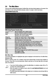
... Menu, press . You can be based on BIOS Setup settings. M85M-US2H E7 . . . . : BIOS Setup : XpressRecovery2 : Boot Menu : Qflash 01/14/2009-NF-MCP78-6A61OG02C-00 Function Keys Function Keys: : BIOS Setup Press the key to enter BIOS Setup or to access the Q-Flash utility in Boot...as needed. : Q-Flash Press the key to enter BIOS Setup first. Note: The setting in BIOS Setup. : XpressRecovery2 If you to set the first boot device without having to access the Q-Flash utility directly without entering BIOS Setup. GA-M85M-US2H Motherboard - 34 - 2-1 Startup Screen The following ...
... Menu, press . You can be based on BIOS Setup settings. M85M-US2H E7 . . . . : BIOS Setup : XpressRecovery2 : Boot Menu : Qflash 01/14/2009-NF-MCP78-6A61OG02C-00 Function Keys Function Keys: : BIOS Setup Press the key to enter BIOS Setup or to access the Q-Flash utility in Boot...as needed. : Q-Flash Press the key to enter BIOS Setup first. Note: The setting in BIOS Setup. : XpressRecovery2 If you to set the first boot device without having to access the Q-Flash utility directly without entering BIOS Setup. GA-M85M-US2H Motherboard - 34 - 2-1 Startup Screen The following ...
Manual
Page 35
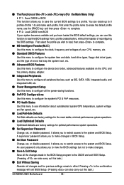
...Save & Exit Setup Exit Without Saving ESC: Quit F8: Q-Flash Select Item F10: Save & Exit Setup F11: Save CMOS to BIOS F12: Load CMOS from BIOS Main Menu Help The onscreen description of a highlighted setup option is displayed on the bottom line of the submenu. • If ... current submenus Access the Q-Flash utility Display system information Save all the changes and exit the BIOS Setup program Save CMOS to BIOS Load CMOS from BIOS Change CPU's Clock & Voltage BIOS Setup Program Function Keys Move the selection bar to select an item Execute command or enter the...
...Save & Exit Setup Exit Without Saving ESC: Quit F8: Q-Flash Select Item F10: Save & Exit Setup F11: Save CMOS to BIOS F12: Load CMOS from BIOS Main Menu Help The onscreen description of a highlighted setup option is displayed on the bottom line of the submenu. • If ... current submenus Access the Q-Flash utility Display system information Save all the changes and exit the BIOS Setup program Save CMOS to BIOS Load CMOS from BIOS Change CPU's Clock & Voltage BIOS Setup Program Function Keys Move the selection bar to select an item Execute command or enter the...
Manual
Page 36
... this menu to configure the system's PCI & PnP resources. PC Health Status Use this function to load the BIOS settings from BIOS If your CPU, memory, etc. Standard CMOS Features Use this menu to configure the system time and date,...BIOS Features Use this menu to configure the device boot order, advanced features available on the CPU, and the primary display adapter. Integrated Peripherals Use this menu to configure all peripheral devices, such as IDE, SATA, USB, integrated audio, and integrated LAN, etc. Power Management Setup Use this task.) GA-M85M-US2H...
... this menu to configure the system's PCI & PnP resources. PC Health Status Use this function to load the BIOS settings from BIOS If your CPU, memory, etc. Standard CMOS Features Use this menu to configure the system time and date,...BIOS Features Use this menu to configure the device boot order, advanced features available on the CPU, and the primary display adapter. Integrated Peripherals Use this menu to configure all peripheral devices, such as IDE, SATA, USB, integrated audio, and integrated LAN, etc. Power Management Setup Use this task.) GA-M85M-US2H...

Manual
Page 37
... you to alter the clock ratio for advanced users only and we recommend you to manually set the PCIe clock frequency. Auto BIOS will work stably with the CPU specifications. BIOS Setup If this feature. - 37 - Incorrectly doing overclock/overvoltage may result in damage to CPU, chipset, or memory and reduce the...
... you to alter the clock ratio for advanced users only and we recommend you to manually set the PCIe clock frequency. Auto BIOS will work stably with the CPU specifications. BIOS Setup If this feature. - 37 - Incorrectly doing overclock/overvoltage may result in damage to CPU, chipset, or memory and reduce the...
Manual
Page 39
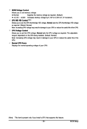
... CPU. Normal sets the CPU Northbridge VID voltage as required. (Default: Normal) Note: Increasing CPU voltage may result in damage to 0.30V at 0.1V increment. BIOS Setup Normal Supplies the memory voltage as required. Normal sets the CPU voltage as required. (Default) +0.10V ~ +0.30V Increases memory voltage by 0.10V to your...
... CPU. Normal sets the CPU Northbridge VID voltage as required. (Default: Normal) Note: Increasing CPU voltage may result in damage to 0.30V at 0.1V increment. BIOS Setup Normal Supplies the memory voltage as required. Normal sets the CPU voltage as required. (Default) +0.10V ~ +0.30V Increases memory voltage by 0.10V to your...

Manual
Page 40
... hard drive access mode. IDE Channel 2, 3 Master/Slave IDE Auto-Detection Press to autodetect the parameters of the IDE/SATA device on this channel. GA-M85M-US2H Motherboard - 40 - 2-4 Standard CMOS Features Date (mm:dd:yy) Time (hh:mm:ss) CMOS Setup Utility-Copyright (C) 1984-2009 Award Software ...format is 13:0:0. IDE Channel 0 Master/Slave Configure your IDE/SATA devices by using one of the three methods below : • Auto Lets BIOS automatically detect IDE/SATA devices during the POST. (Default) • None If no IDE/SATA devices are used , set this item to None ...
... hard drive access mode. IDE Channel 2, 3 Master/Slave IDE Auto-Detection Press to autodetect the parameters of the IDE/SATA device on this channel. GA-M85M-US2H Motherboard - 40 - 2-4 Standard CMOS Features Date (mm:dd:yy) Time (hh:mm:ss) CMOS Setup Utility-Copyright (C) 1984-2009 Award Software ...format is 13:0:0. IDE Channel 0 Master/Slave Configure your IDE/SATA devices by using one of the three methods below : • Auto Lets BIOS automatically detect IDE/SATA devices during the POST. (Default) • None If no IDE/SATA devices are used , set this item to None ...


