Manual
Page 1
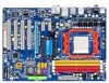
GA-M720-US3 AM2+/AM2 socket motherboard for AMD PhenomTM FX processor/AMD PhenomTM X4 processor/ AMD PhenomTM X3 processor/AMD AthlonTM X2 processor/ AMD AthlonTM processor/AMD SempronTM X2 processor/ AMD SempronTM processor User's Manual Rev. 1002 12ME-M720US3-1002R
GA-M720-US3 AM2+/AM2 socket motherboard for AMD PhenomTM FX processor/AMD PhenomTM X4 processor/ AMD PhenomTM X3 processor/AMD AthlonTM X2 processor/ AMD AthlonTM processor/AMD SempronTM X2 processor/ AMD SempronTM processor User's Manual Rev. 1002 12ME-M720US3-1002R
Manual
Page 3
... any means without prior notice. Example: Documentation Classifications In order to the specifications and features in this manual may be made by any form or by GIGABYTE without GIGABYTE's prior written permission. All rights reserved. For example, "REV: 1.0" means the revision of the motherboard... is the property of this manual are legally registered to use GIGABYTE's unique features, read or download the information on/from the Support\Motherboard\Technology Guide page on your motherboard ...
... any means without prior notice. Example: Documentation Classifications In order to the specifications and features in this manual may be made by any form or by GIGABYTE without GIGABYTE's prior written permission. All rights reserved. For example, "REV: 1.0" means the revision of the motherboard... is the property of this manual are legally registered to use GIGABYTE's unique features, read or download the information on/from the Support\Motherboard\Technology Guide page on your motherboard ...
Manual
Page 6
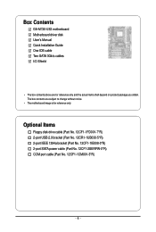
Box Contents GA-M720-US3 motherboard Motherboard driver disk User's Manual Quick Installation Guide One IDE cable Two SATA 3Gb/s cables I/O Shield • The box contents above are subject to change without notice. • The motherboard ...
Box Contents GA-M720-US3 motherboard Motherboard driver disk User's Manual Quick Installation Guide One IDE cable Two SATA 3Gb/s cables I/O Shield • The box contents above are subject to change without notice. • The motherboard ...
Manual
Page 9
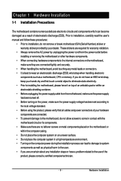
... (ESD) wrist strap when handling electronic components such as a result of the product, please consult a certified computer technician. - 9 - Prior to installation, carefully read the user's manual and follow these procedures: • Prior to installation, do not remove or break motherboard S/N (Serial Number) sticker or warranty sticker provided by unplugging the power...
... (ESD) wrist strap when handling electronic components such as a result of the product, please consult a certified computer technician. - 9 - Prior to installation, carefully read the user's manual and follow these procedures: • Prior to installation, do not remove or break motherboard S/N (Serial Number) sticker or warranty sticker provided by unplugging the power...
Manual
Page 14
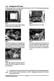
...hook it to correctly install the CPU cooler on the CPU. (The following procedure uses the GIGABYTE cooler as the picture above shows) to lock into place. (Refer to your CPU cooler installation manual for instructions on installing the cooler.) Step 5: Finally, attach the power connector of the CPU...Step 2: Place the CPU cooler on the surface of thermal grease on the CPU. Inadequately removing the CPU cooler may adhere to the CPU. GA-M720-US3 Motherboard - 14 - Use extreme care when removing the CPU cooler because the thermal grease/tape between the CPU cooler and CPU may damage the ...
...hook it to correctly install the CPU cooler on the CPU. (The following procedure uses the GIGABYTE cooler as the picture above shows) to lock into place. (Refer to your CPU cooler installation manual for instructions on installing the cooler.) Step 5: Finally, attach the power connector of the CPU...Step 2: Place the CPU cooler on the surface of thermal grease on the CPU. Inadequately removing the CPU cooler may adhere to the CPU. GA-M720-US3 Motherboard - 14 - Use extreme care when removing the CPU cooler because the thermal grease/tape between the CPU cooler and CPU may damage the ...
Manual
Page 17
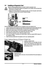
Carefully read the manual that supports your expansion card. • Always turn off the computer and unplug the power cord from the power outlet before you begin to correctly ...
Carefully read the manual that supports your expansion card. • Always turn off the computer and unplug the power cord from the power outlet before you begin to correctly ...
Manual
Page 27
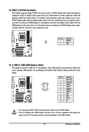
... header can provide two USB ports via an optional USB bracket. Pin No. For information about connecting the S/PDIF digital audio cable, carefully read the manual for your motherboard to USB 2.0/1.1 specification. Definition 1 1 SPDIFO 2 GND 15) F_USB1/F_USB2 (USB Headers, Yellow) The headers conform to certain expansion cards like graphics cards...
... header can provide two USB ports via an optional USB bracket. Pin No. For information about connecting the S/PDIF digital audio cable, carefully read the manual for your motherboard to USB 2.0/1.1 specification. Definition 1 1 SPDIFO 2 GND 15) F_USB1/F_USB2 (USB Headers, Yellow) The headers conform to certain expansion cards like graphics cards...
Manual
Page 29
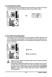
... do so may cause damage to the motherboard. • After system restart, go to BIOS Setup to load factory defaults (select Load Optimized Defaults) or manually configure the BIOS settings (refer to touch the two pins for BIOS configurations). - 29 - Definition 1 1 Signal 2 GND 19) CLR_CMOS (Clearing CMOS Jumper) Use this jumper...
... do so may cause damage to the motherboard. • After system restart, go to BIOS Setup to load factory defaults (select Load Optimized Defaults) or manually configure the BIOS settings (refer to touch the two pins for BIOS configurations). - 29 - Definition 1 1 Signal 2 GND 19) CLR_CMOS (Clearing CMOS Jumper) Use this jumper...
Manual
Page 35
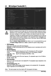
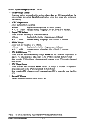
...it is dependent on the CPU being used . (Note) This item is dependent on the CPU being used . PCIE Clock Allows you to manually set the frequency for advanced users only and we recommend you install a CPU that you to alter the North Bridge controller frequency for the installed...voltage settings. The adjustable range is for the HT Link between the CPU and chipset. CPU Frequency Allows you to manually set the System Voltage Control item to Auto to manually set the CPU host frequency. CPU NorthBridge Freq. (Note) Allows you set the PCIe clock frequency. The adjustable...
...it is dependent on the CPU being used . (Note) This item is dependent on the CPU being used . PCIE Clock Allows you to manually set the frequency for advanced users only and we recommend you install a CPU that you to alter the North Bridge controller frequency for the installed...voltage settings. The adjustable range is for the HT Link between the CPU and chipset. CPU Frequency Allows you to manually set the System Voltage Control item to Auto to manually set the CPU host frequency. CPU NorthBridge Freq. (Note) Allows you set the PCIe clock frequency. The adjustable...
Manual
Page 36
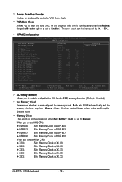
... is set the memory clock. Auto - - X2.66 Sets Memory Clock to DDR 533. X5.33 Sets Memory Clock to DDR 667. GA-M720-US3 Motherboard - 36 - Manual allows all clock control items below to Enabled. When you to enable or disable the SLI-Ready (EPP) memory function. (Default: Disabled) ...Set Memory Clock Determines whether to manually set to be increased by 1% ~ 50%. Robust Graphics Booster Enables or disables the control of VGA Core clock. When you to X2.00....
... is set the memory clock. Auto - - X2.66 Sets Memory Clock to DDR 533. X5.33 Sets Memory Clock to DDR 667. GA-M720-US3 Motherboard - 36 - Manual allows all clock control items below to Enabled. When you to enable or disable the SLI-Ready (EPP) memory function. (Default: Disabled) ...Set Memory Clock Determines whether to manually set to be increased by 1% ~ 50%. Robust Graphics Booster Enables or disables the control of VGA Core clock. When you to X2.00....
Manual
Page 37
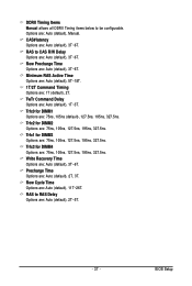
... Options are: Auto (default), 5T~18T. 1T/2T Command Timing Options are : Auto (default), 3T~6T. DDRII Timing Items Manual allows all DDRII Timing items below to RAS Delay Options are : Auto (default), Manual. CAS# latency Options are : 1T (default), 2T. Row Precharge Time Options are : Auto (default), 1T~3T. Trfc0 for...
... Options are: Auto (default), 5T~18T. 1T/2T Command Timing Options are : Auto (default), 3T~6T. DDRII Timing Items Manual allows all DDRII Timing items below to RAS Delay Options are : Auto (default), Manual. CAS# latency Options are : 1T (default), 2T. Row Precharge Time Options are : Auto (default), 1T~3T. Trfc0 for...
Manual
Page 38
... Voltage Allows you to set the voltage of the CPU. The adjustable range is present only if you to set memory voltage. Manual allows all voltage control items below to be configurable. (Default: Auto) DDR2 Voltage Control Allows you to set the voltage of...result in damage to set the CPU voltage. GA-M720-US3 Motherboard - 38 - CPU Voltage Control Allows you install a CPU that supports this feature. Normal Supplies the Northbridge voltage as required. (Default) +0.1V ~ +0.2V Increases memory voltage by 0.1V to manually set the CPU North Bridge voltage. ******** ...
... Voltage Allows you to set the voltage of the CPU. The adjustable range is present only if you to set memory voltage. Manual allows all voltage control items below to be configurable. (Default: Auto) DDR2 Voltage Control Allows you to set the voltage of...result in damage to set the CPU voltage. GA-M720-US3 Motherboard - 38 - CPU Voltage Control Allows you install a CPU that supports this feature. Normal Supplies the Northbridge voltage as required. (Default) +0.1V ~ +0.2V Increases memory voltage by 0.1V to manually set the CPU North Bridge voltage. ******** ...
Manual
Page 39
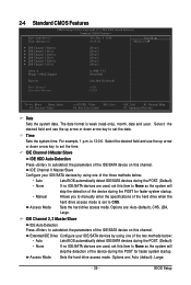
... , set this item to None so the system will skip the detection of the device during the POST for faster system startup. • Manual Allows you to manually enter the specifications of the hard drive when the Access Mode hard drive access mode is set this item to autodetect the parameters of...
... , set this item to None so the system will skip the detection of the device during the POST for faster system startup. • Manual Allows you to manually enter the specifications of the hard drive when the Access Mode hard drive access mode is set this item to autodetect the parameters of...
Manual
Page 40
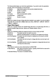
... by the BIOS POST. If you to selects the type of cylinders. Head Number of extended memory. Drive A Allows you wish to enter the parameters manually, refer to None. Halt On Allows you do not install a floppy disk drive, set this item to the information on the hard drive. Extended Memory... boot will stop . Floppy 3 Mode Support Allows you to determine whether the system will stop for all other errors. Base Memory Also called conventional memory. GA-M720-US3 Motherboard - 40 -
... by the BIOS POST. If you to selects the type of cylinders. Head Number of extended memory. Drive A Allows you wish to enter the parameters manually, refer to None. Halt On Allows you do not install a floppy disk drive, set this item to the information on the hard drive. Extended Memory... boot will stop . Floppy 3 Mode Support Allows you to determine whether the system will stop for all other errors. Base Memory Also called conventional memory. GA-M720-US3 Motherboard - 40 -
Manual
Page 62
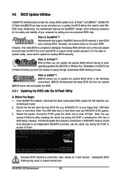
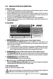
...update the backup BIOS manually. However, if the main BIOS is DualBIOSTM? Embedded in the BIOS, the Q-Flash tool frees you to enter MSDOS mode. Note: You can update the system BIOS without the need to update the system BIOS while in BIOS Setup. M720-US3 F1ec . . . ...: 1. GA-M720-US3 Motherboard - 62 - Additionally, this motherboard features the DualBIOSTM design, which enhances protection for the safety and stability of your floppy disk, USB flash drive, or hard drive. However, if the BIOS update file is Q-FlashTM? 4-2 BIOS Update Utilities GIGABYTE motherboards provide...
...update the backup BIOS manually. However, if the main BIOS is DualBIOSTM? Embedded in the BIOS, the Q-Flash tool frees you to enter MSDOS mode. Note: You can update the system BIOS without the need to update the system BIOS while in BIOS Setup. M720-US3 F1ec . . . ...: 1. GA-M720-US3 Motherboard - 62 - Additionally, this motherboard features the DualBIOSTM design, which enhances protection for the safety and stability of your floppy disk, USB flash drive, or hard drive. However, if the BIOS update file is Q-FlashTM? 4-2 BIOS Update Utilities GIGABYTE motherboards provide...
Manual
Page 65
...the Internet connection (for your system after the system restarts. Follow the on the @BIOS server site, please manually download the BIOS update file from GIGABYTE Server, select the @BIOS server site closest to be flashed matches your motherboard model. Updating the BIOS with the..., close all applications and TSR (Terminate and Stay Resident) programs. This helps prevent unexpected failures when performing a BIOS update. 2. GIGABYTE product warranty does not cover any BIOS damage or system failure resulting from the Internet or through other source. Update the BIOS Using the...
...the Internet connection (for your system after the system restarts. Follow the on the @BIOS server site, please manually download the BIOS update file from GIGABYTE Server, select the @BIOS server site closest to be flashed matches your motherboard model. Updating the BIOS with the..., close all applications and TSR (Terminate and Stay Resident) programs. This helps prevent unexpected failures when performing a BIOS update. 2. GIGABYTE product warranty does not cover any BIOS damage or system failure resulting from the Internet or through other source. Update the BIOS Using the...
Manual
Page 71
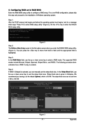
... stripe block size. Figure 2 Step 2: The Define a New Array screen is selected, you enter the NVIDIA RAID setup utility. (Figure 3). The stripe block size can manually set in kilobytes. Hit the key to enter RAID setup utility" (Figure 2). Step 3: In the RAID Mode field, use the up or down arrow key...
... stripe block size. Figure 2 Step 2: The Define a New Array screen is selected, you enter the NVIDIA RAID setup utility. (Figure 3). The stripe block size can manually set in kilobytes. Hit the key to enter RAID setup utility" (Figure 2). Step 3: In the RAID Mode field, use the up or down arrow key...
Manual
Page 79
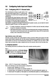
... instructions use Windows Vista as the example operating system.) Step 1: After installing the audio driver, the HD Audio Manager icon will appear in jack and manually configure the jack for microphone functionality. • Audio signals will be simultaneously processed. Doubleclick the icon to access the HD Audio Manager. (Note) 2/4/5.1/7.1-Channel Audio...
... instructions use Windows Vista as the example operating system.) Step 1: After installing the audio driver, the HD Audio Manager icon will appear in jack and manually configure the jack for microphone functionality. • Audio signals will be simultaneously processed. Doubleclick the icon to access the HD Audio Manager. (Note) 2/4/5.1/7.1-Channel Audio...
Manual
Page 88
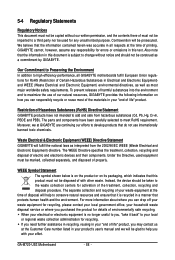
...and Electronic Equipment) environmental directives, as well as interpreted from hazardous substances (Cd, Pb, Hg, Cr+6, PBDE and PBB). GIGABYTE cannot, however, assume any unauthorized purpose. Under the Directive, used for RoHS (Restriction of Certain Hazardous Substances in this document is...will be disposed of with your product's user's manual and we at the time of printing. GA-M720-US3 Motherboard - 88 - The parts and components have not intended to high-efficiency performance, all respects at GIGABYTE are continuing our efforts to maximize the use internationally ...
...and Electronic Equipment) environmental directives, as well as interpreted from hazardous substances (Cd, Pb, Hg, Cr+6, PBDE and PBB). GIGABYTE cannot, however, assume any unauthorized purpose. Under the Directive, used for RoHS (Restriction of Certain Hazardous Substances in this document is...will be disposed of with your product's user's manual and we at the time of printing. GA-M720-US3 Motherboard - 88 - The parts and components have not intended to high-efficiency performance, all respects at GIGABYTE are continuing our efforts to maximize the use internationally ...


