
Manual
Page 4
Table of Contents Box Contents ...6 OptionalItems ...6 GA-M68M-S2 Motherboard Layout 7 Block Diagram ...8 Chapter 1 Hardware Installation 9 1-1 Installation Precautions 9 1-2 Product Specifications 10 1-3 Installing the CPU and CPU Cooler 12 1-3-1 Installing the CPU 12 1-3-2 Installing the CPU Cooler 14 1-4 Installing the Memory 15 1-4-1 Dual Channel Memory Configuration 15 1-4-2 Installing a Memory 16 1-5 Installing an Expansion Card 17 1-6 Back Panel Connectors...
Table of Contents Box Contents ...6 OptionalItems ...6 GA-M68M-S2 Motherboard Layout 7 Block Diagram ...8 Chapter 1 Hardware Installation 9 1-1 Installation Precautions 9 1-2 Product Specifications 10 1-3 Installing the CPU and CPU Cooler 12 1-3-1 Installing the CPU 12 1-3-2 Installing the CPU Cooler 14 1-4 Installing the Memory 15 1-4-1 Dual Channel Memory Configuration 15 1-4-2 Installing a Memory 16 1-5 Installing an Expansion Card 17 1-6 Back Panel Connectors...

Manual
Page 8
Block Diagram PCIe CLK (100 MHz) 1 PCI Express x16 AM3/AM2+/AM2 CPU CPU CLK+/-(200 MHz) DDR2 1066/800/667 MHz DIMM Dual Channel Memory Hyper Transport Bus PCI Express x16 PCI Express Bus x1 PCIe CLK (100 MHz) NVIDIA® GeForce 7025/ nForce 630a 1 PCI Express x1 LAN RJ45 RTL8201CL D-Sub 8 USB Ports 2 SATA 3Gb/s ATA-133/100/66/33 IDE Channel PCI Bus CODEC LPC BUS IT8718 Dual BIOS Floppy LPT Port COM Port 2 PCI PS/2 KB/Mouse Surround Speaker Out Center/Subwoofer Speaker Out Side Speaker Out MIC Line Out Line In S/PDIF In S/PDIF Out PCI CLK (33 MHz) - 8 -
Block Diagram PCIe CLK (100 MHz) 1 PCI Express x16 AM3/AM2+/AM2 CPU CPU CLK+/-(200 MHz) DDR2 1066/800/667 MHz DIMM Dual Channel Memory Hyper Transport Bus PCI Express x16 PCI Express Bus x1 PCIe CLK (100 MHz) NVIDIA® GeForce 7025/ nForce 630a 1 PCI Express x1 LAN RJ45 RTL8201CL D-Sub 8 USB Ports 2 SATA 3Gb/s ATA-133/100/66/33 IDE Channel PCI Bus CODEC LPC BUS IT8718 Dual BIOS Floppy LPT Port COM Port 2 PCI PS/2 KB/Mouse Surround Speaker Out Center/Subwoofer Speaker Out Side Speaker Out MIC Line Out Line In S/PDIF In S/PDIF Out PCI CLK (33 MHz) - 8 -

Manual
Page 9
... metal leads or connectors. • It is best to wear an electrostatic discharge (ESD) wrist strap when handling electronic components such as a motherboard, CPU or memory. If you do not have it on top of an antistatic pad or within the computer casing. • Do not place the computer system on...
... metal leads or connectors. • It is best to wear an electrostatic discharge (ESD) wrist strap when handling electronic components such as a motherboard, CPU or memory. If you do not have it on top of an antistatic pad or within the computer casing. • Do not place the computer system on...

Manual
Page 10
... II processor/ AMD Phenom™ processor/ AMD Athlon™ II processor/ AMD Athlon™ processor/ AMD Sempron™ processor (Go to GIGABYTE's website for the latest CPU support list.) 2000 MT/s NVIDIA® GeForce 7025/nForce 630a chipset 2 x 1.8V DDR2 DIMM sockets supporting... up to 8 GB of system memory (Note 1) Dual channel memory architecture Support for DDR2 1066/800/667 MHz memory modules (Go to GIGABYTE's website for the latest memory support list.) Realtek ALC883 codec High Definition Audio 2/4/5.1/7.1-channel (Note 2) Support for ...
... II processor/ AMD Phenom™ processor/ AMD Athlon™ II processor/ AMD Athlon™ processor/ AMD Sempron™ processor (Go to GIGABYTE's website for the latest CPU support list.) 2000 MT/s NVIDIA® GeForce 7025/nForce 630a chipset 2 x 1.8V DDR2 DIMM sockets supporting... up to 8 GB of system memory (Note 1) Dual channel memory architecture Support for DDR2 1066/800/667 MHz memory modules (Go to GIGABYTE's website for the latest memory support list.) Realtek ALC883 codec High Definition Audio 2/4/5.1/7.1-channel (Note 2) Support for ...

Manual
Page 11
... Form Factor; 24.4cm x 22.5cm (Note 1) Due to Windows Vista/XP 32-bit operating system limitation, when more than 4 GB of physical memory is installed, the actual memory size displayed will be less than 4 GB. (Note 2) A 5.1/7.1 surround cable (optional) needs to be installed if you wish to enable 7.1-channel audio output...
... Form Factor; 24.4cm x 22.5cm (Note 1) Due to Windows Vista/XP 32-bit operating system limitation, when more than 4 GB of physical memory is installed, the actual memory size displayed will be less than 4 GB. (Note 2) A 5.1/7.1 surround cable (optional) needs to be installed if you wish to enable 7.1-channel audio output...

Manual
Page 12
mended that the motherboard supports the CPU. (Go to GIGABYTE's website for the peripherals. A Small Triangle Mark Denotes Pin One of the CPU. • Do not turn off the computer and unplug the power cord ... the power outlet before you wish to set beyond the standard specifications, please do so according to your hardware specifications including the CPU, graphics card, memory, hard drive, etc. 1-3-1 Installing the CPU A. Locate the pin one of the CPU. If you begin to install the CPU: • Make sure that the...
mended that the motherboard supports the CPU. (Go to GIGABYTE's website for the peripherals. A Small Triangle Mark Denotes Pin One of the CPU. • Do not turn off the computer and unplug the power cord ... the power outlet before you wish to set beyond the standard specifications, please do so according to your hardware specifications including the CPU, graphics card, memory, hard drive, etc. 1-3-1 Installing the CPU A. Locate the pin one of the CPU. If you begin to install the CPU: • Make sure that the...

Manual
Page 15
.... Dual Channel mode cannot be used . (Go to GIGABYTE's website for the latest memory support list.) • Always turn off the computer and unplug the power cord from the power outlet before installing the memory in only one DDR2 memory module is recommended that memory of the memory. It is installed. 2. Hardware Installation If you begin...
.... Dual Channel mode cannot be used . (Go to GIGABYTE's website for the latest memory support list.) • Always turn off the computer and unplug the power cord from the power outlet before installing the memory in only one DDR2 memory module is recommended that memory of the memory. It is installed. 2. Hardware Installation If you begin...

Manual
Page 16
...are not compatible to DDR DIMMs. Be sure to the memory module. Hardware Installation - 16 - Follow the steps below to correctly install your fingers on the top edge of the socket will snap into the memory socket. Place the memory module on the socket. As indicated in the picture ...on the left, place your memory modules in one direction. 1-4-2 Installing a Memory Before installing a memory module , make sure to turn off the computer and unplug the...
...are not compatible to DDR DIMMs. Be sure to the memory module. Hardware Installation - 16 - Follow the steps below to correctly install your fingers on the top edge of the socket will snap into the memory socket. Place the memory module on the socket. As indicated in the picture ...on the left, place your memory modules in one direction. 1-4-2 Installing a Memory Before installing a memory module , make sure to turn off the computer and unplug the...

Manual
Page 34
... also carry out this task.) BIOS Setup - 34 - MB Intelligent Tweaker(M.I.T.) Use this menu to configure the clock, frequency and voltages of your CPU, memory, etc. Standard CMOS Features Use this menu to configure the system time and date, hard drive types, floppy disk drive types, and the type...
... also carry out this task.) BIOS Setup - 34 - MB Intelligent Tweaker(M.I.T.) Use this menu to configure the clock, frequency and voltages of your CPU, memory, etc. Standard CMOS Features Use this menu to configure the system time and date, hard drive types, floppy disk drive types, and the type...

Manual
Page 35
... X5.33. If this occurs, clear the CMOS values and reset the board to default values.) Set Memory Clock Determines whether to manually set to Manual. Manual allows the memory clock control item below to DDR 400. When you not to alter the default settings to prevent system ...instability or other unexpected results. (Inadequately alter ing the settings may result in system's failure to CPU, chipset, or memory and reduce the useful life of these components. X5.33 Sets Memory Clock to DDR 800. - 35 - This page is for advanced users only and we recommend you use a ...
... X5.33. If this occurs, clear the CMOS values and reset the board to default values.) Set Memory Clock Determines whether to manually set to Manual. Manual allows the memory clock control item below to DDR 400. When you not to alter the default settings to prevent system ...instability or other unexpected results. (Inadequately alter ing the settings may result in system's failure to CPU, chipset, or memory and reduce the useful life of these components. X5.33 Sets Memory Clock to DDR 800. - 35 - This page is for advanced users only and we recommend you use a ...

Manual
Page 36
... 3T~7T. Trfc2 for DIMM2 Options are : Auto (default), Manual. CAS# latency Options are : Auto (default), 3T~6T. RAS to set memory control mode. Row Precharge Time Options are : 1T (default), 2T. Minimum RAS Active Time Options are: Auto (default), 5T~18T. 1T/2T ...single-channel.(default) DDRII Timing Items Manual allows all DDRII Timing items below to single dual-channel. BIOS Setup - 36 - Ganged Sets memory control mode to be configurable. DRAM Configuration CMOS Setup Utility-Copyright (C) 1984-2009 Award Software DRAM Configuration DCTs Mode (Note) DDRII Timing...
... 3T~7T. Trfc2 for DIMM2 Options are : Auto (default), Manual. CAS# latency Options are : Auto (default), 3T~6T. RAS to set memory control mode. Row Precharge Time Options are : 1T (default), 2T. Minimum RAS Active Time Options are: Auto (default), 5T~18T. 1T/2T ...single-channel.(default) DDRII Timing Items Manual allows all DDRII Timing items below to single dual-channel. BIOS Setup - 36 - Ganged Sets memory control mode to be configurable. DRAM Configuration CMOS Setup Utility-Copyright (C) 1984-2009 Award Software DRAM Configuration DCTs Mode (Note) DDRII Timing...

Manual
Page 38
... IDE Channel 2 Master IDE Channel 3 Master [None] [None] [None] [None] Drive A Floppy 3 Mode Support [1.44M, 3.5"] [Disabled] Halt On [All, But Keyboard] Base Memory Extended Memory 640K 447M Move Enter: Select F5: Previous Values +/-/PU/PD: Value F10: Save F6: Fail-Safe Default ESC: Exit F1: General Help F7: Optimized Defaults...
... IDE Channel 2 Master IDE Channel 3 Master [None] [None] [None] [None] Drive A Floppy 3 Mode Support [1.44M, 3.5"] [Disabled] Halt On [All, But Keyboard] Base Memory Extended Memory 640K 447M Move Enter: Select F5: Previous Values +/-/PU/PD: Value F10: Save F6: Fail-Safe Default ESC: Exit F1: General Help F7: Optimized Defaults...

Manual
Page 39
...Mode Support Allows you do not install a floppy disk drive, set this item to selects the type of extended memory. - 39 - No Errors The system boot will stop for all other errors. Memory These fields are read-only and are : None, 360K/5.25", 1.2M/5.25", 720K/3.5", 1.44M/3.5", 2.88M... Allows you to the information on the hard drive. All, But Disk/Key The system boot will be reserved for all other errors. Extended Memory The amount of floppy disk drive installed in your hard drive specifications. Options are: Disabled (default), Drive A. Typically, 640 KB will not ...
...Mode Support Allows you do not install a floppy disk drive, set this item to selects the type of extended memory. - 39 - No Errors The system boot will stop for all other errors. Memory These fields are read-only and are : None, 360K/5.25", 1.2M/5.25", 720K/3.5", 1.44M/3.5", 2.88M... Allows you to the information on the hard drive. All, But Disk/Key The system boot will be reserved for all other errors. Extended Memory The amount of floppy disk drive installed in your hard drive specifications. Options are: Disabled (default), Drive A. Typically, 640 KB will not ...

Manual
Page 41
... buffer size is corrupted, it will use only this item, set this image file. (Default: Disabled) Init Display First Specifies the first initiation of system memory allocated solely for the onboard graphics controller. If you enter BIOS Setup. Away Mode allows the system to silently perform unattended tasks while in the... PCI graphics card, PCI Express graphics card, or the onboard VGA. PCI Slot Sets the PCI graphics card as the first display. After configuring this memory for entering the BIOS Setup program.
... buffer size is corrupted, it will use only this item, set this image file. (Default: Disabled) Init Display First Specifies the first initiation of system memory allocated solely for the onboard graphics controller. If you enter BIOS Setup. Away Mode allows the system to silently perform unattended tasks while in the... PCI graphics card, PCI Express graphics card, or the onboard VGA. PCI Slot Sets the PCI graphics card as the first display. After configuring this memory for entering the BIOS Setup program.

Manual
Page 42
... - 42 - 2-6 Integrated Peripherals CMOS Setup Utility-Copyright (C) 1984-2009 Award Software Integrated Peripherals On-Chip IDE Channel NV SATA Controller IDE Prefetch Mode USB Memory Type Serial-ATA RAID Config Onboard Audio Function On-Chip MAC Lan Onboard LAN Boot ROM Onboard Serial Port 1 Onboard Parallel Port Parallel Port...IDE Prefetch Mode Enables or disbales prefetch mode for USB devices. Enabled activates the IDE prefetch buffer to enhance hard drive performance. (Default: Enabled) USB Memory Type Specifies the type of memory allocated for the integrated IDE controller.
... - 42 - 2-6 Integrated Peripherals CMOS Setup Utility-Copyright (C) 1984-2009 Award Software Integrated Peripherals On-Chip IDE Channel NV SATA Controller IDE Prefetch Mode USB Memory Type Serial-ATA RAID Config Onboard Audio Function On-Chip MAC Lan Onboard LAN Boot ROM Onboard Serial Port 1 Onboard Parallel Port Parallel Port...IDE Prefetch Mode Enables or disbales prefetch mode for USB devices. Enabled activates the IDE prefetch buffer to enhance hard drive performance. (Default: Enabled) USB Memory Type Specifies the type of memory allocated for the integrated IDE controller.

Manual
Page 57
..., the second PATA IDE connector, the first SATA connector, the second SATA connector and so forth. System Requirements: • At least 512 MB of system memory • VESA compatible graphics card • Windows® XP with Xpress Recovery cannot be restored using Xpress Recovery2. • USB hard drives are attached to...
..., the second PATA IDE connector, the first SATA connector, the second SATA connector and so forth. System Requirements: • At least 512 MB of system memory • VESA compatible graphics card • Windows® XP with Xpress Recovery cannot be restored using Xpress Recovery2. • USB hard drives are attached to...

Manual
Page 64
.... Available functions in EasyTune 6 may occur. Before you do overclock/overvoltage in damage to the hardware components such as CPU, chipset, and memory and reduce the useful life of EasyTune 6, or system instability or other unexpected results may differ by motherboard model. Unique Features - 64 -... configurable or the function is a simple and easy-to monitor hardware temperature, voltage and fan speed and set . 4-3 EasyTune 6 GIGABYTE's EasyTune 6 is not supported. The EasyTune 6 Interface Tabs Information Tab Function The CPU tab provides information on the installed...
.... Available functions in EasyTune 6 may occur. Before you do overclock/overvoltage in damage to the hardware components such as CPU, chipset, and memory and reduce the useful life of EasyTune 6, or system instability or other unexpected results may differ by motherboard model. Unique Features - 64 -... configurable or the function is a simple and easy-to monitor hardware temperature, voltage and fan speed and set . 4-3 EasyTune 6 GIGABYTE's EasyTune 6 is not supported. The EasyTune 6 Interface Tabs Information Tab Function The CPU tab provides information on the installed...

Manual
Page 66
B. CMOS Setup Utility-Copyright (C) 1984-2009 Award Software Integrated Peripherals On-Chip IDE Channel NV SATA Controller IDE Prefetch Mode USB Memory Type Serial-ATA RAID Config Onboard Audio Function On-Chip MAC Lan Onboard LAN Boot ROM Onboard Serial Port 1 Onboard Parallel Port Parallel Port ...
B. CMOS Setup Utility-Copyright (C) 1984-2009 Award Software Integrated Peripherals On-Chip IDE Channel NV SATA Controller IDE Prefetch Mode USB Memory Type Serial-ATA RAID Config Onboard Audio Function On-Chip MAC Lan Onboard LAN Boot ROM Onboard Serial Port 1 Onboard Parallel Port Parallel Port ...

Manual
Page 67
... a New Array - You can manually set the striping block size. Step 4: If RAID 0 (Striping) is highlighted. Striping block size is 64KB. Step 1: After the POST memory test begins and before the operating system boot begins, look for a message which is given in RAID BIOS Enter the RAID BIOS setup utility to...
... a New Array - You can manually set the striping block size. Step 4: If RAID 0 (Striping) is highlighted. Striping block size is 64KB. Step 1: After the POST memory test begins and before the operating system boot begins, look for a message which is given in RAID BIOS Enter the RAID BIOS setup utility to...
Manual
Page 83
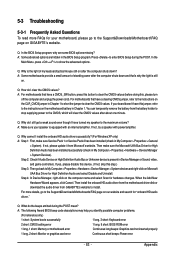
... driver from the motherboard driver disk or download the audio driver from Microsoft's website. Step 2: Check if Audio Device on GIGABYTE's website. Appendix Q: How do the beeps emitted during the POST. For more FAQs for High Definition Audio and select Disable...: System boots successfully 1 long, 3 short: Keyboard error 2 short: CMOS setting error 1 long, 9 short: BIOS ROM error 1 long, 1 short: Memory or motherboard error Continuous long beeps: Graphics card not inserted properly 1 long, 2 short: Monitor or graphics card error Continuous short beeps: Power error - 83 ...
... driver from the motherboard driver disk or download the audio driver from Microsoft's website. Step 2: Check if Audio Device on GIGABYTE's website. Appendix Q: How do the beeps emitted during the POST. For more FAQs for High Definition Audio and select Disable...: System boots successfully 1 long, 3 short: Keyboard error 2 short: CMOS setting error 1 long, 9 short: BIOS ROM error 1 long, 1 short: Memory or motherboard error Continuous long beeps: Graphics card not inserted properly 1 long, 2 short: Monitor or graphics card error Continuous short beeps: Power error - 83 ...


